
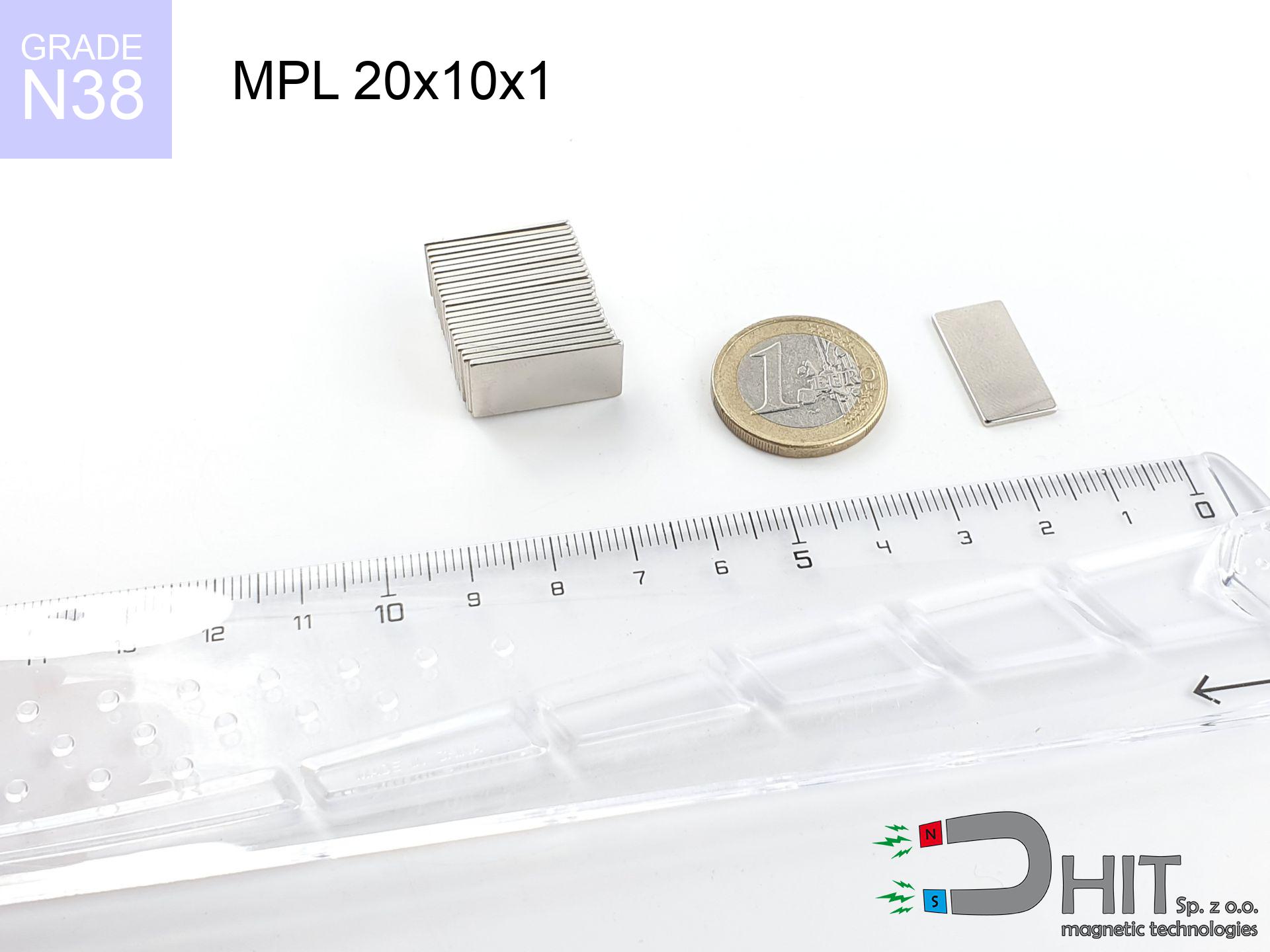
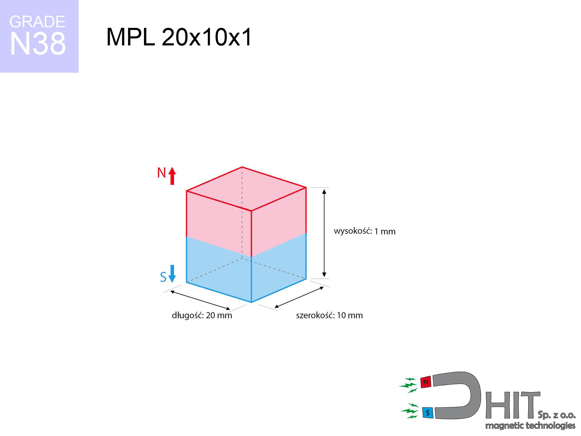
MPL 20x10x1 / N38 - lamellar magnet
lamellar magnet
Catalog no 020126
GTIN/EAN: 5906301811329
length
20 mm [±0,1 mm]
Width
10 mm [±0,1 mm]
Height
1 mm [±0,1 mm]
Weight
1.5 g
Magnetization Direction
↑ axial
Load capacity
0.56 kg / 5.46 N
Magnetic Induction
87.15 mT / 871 Gs
Coating
[NiCuNi] Nickel
0.996 ZŁ with VAT / pcs + price for transport
0.810 ZŁ net + 23% VAT / pcs
bulk discounts:
Need more?
Give us a call
+48 888 99 98 98
if you prefer drop us a message using
form
the contact page.
Weight along with structure of a neodymium magnet can be calculated on our
magnetic mass calculator.
Order by 14:00 and we’ll ship today!
Technical of the product - MPL 20x10x1 / N38 - lamellar magnet
Specification / characteristics - MPL 20x10x1 / N38 - lamellar magnet
| properties | values |
|---|---|
| Cat. no. | 020126 |
| GTIN/EAN | 5906301811329 |
| Production/Distribution | Dhit sp. z o.o. |
| Country of origin | Poland / China / Germany |
| Customs code | 85059029 |
| length | 20 mm [±0,1 mm] |
| Width | 10 mm [±0,1 mm] |
| Height | 1 mm [±0,1 mm] |
| Weight | 1.5 g |
| Magnetization Direction | ↑ axial |
| Load capacity ~ ? | 0.56 kg / 5.46 N |
| Magnetic Induction ~ ? | 87.15 mT / 871 Gs |
| Coating | [NiCuNi] Nickel |
| Manufacturing Tolerance | ±0.1 mm |
Magnetic properties of material N38
| properties | values | units |
|---|---|---|
| remenance Br [min. - max.] ? | 12.2-12.6 | kGs |
| remenance Br [min. - max.] ? | 1220-1260 | mT |
| coercivity bHc ? | 10.8-11.5 | kOe |
| coercivity bHc ? | 860-915 | kA/m |
| actual internal force iHc | ≥ 12 | kOe |
| actual internal force iHc | ≥ 955 | kA/m |
| energy density [min. - max.] ? | 36-38 | BH max MGOe |
| energy density [min. - max.] ? | 287-303 | BH max KJ/m |
| max. temperature ? | ≤ 80 | °C |
Physical properties of sintered neodymium magnets Nd2Fe14B at 20°C
| properties | values | units |
|---|---|---|
| Vickers hardness | ≥550 | Hv |
| Density | ≥7.4 | g/cm3 |
| Curie Temperature TC | 312 - 380 | °C |
| Curie Temperature TF | 593 - 716 | °F |
| Specific resistance | 150 | μΩ⋅cm |
| Bending strength | 250 | MPa |
| Compressive strength | 1000~1100 | MPa |
| Thermal expansion parallel (∥) to orientation (M) | (3-4) x 10-6 | °C-1 |
| Thermal expansion perpendicular (⊥) to orientation (M) | -(1-3) x 10-6 | °C-1 |
| Young's modulus | 1.7 x 10⁴ | kg/mm² |
Engineering modeling of the product - data
These values represent the outcome of a physical simulation. Results were calculated on models for the class Nd2Fe14B. Actual conditions may differ. Use these calculations as a reference point when designing systems.
Table 1: Static pull force (force vs distance) - characteristics
MPL 20x10x1 / N38
| Distance (mm) | Induction (Gauss) / mT | Pull Force (kg/lbs/g/N) | Risk Status |
|---|---|---|---|
| 0 mm |
871 Gs
87.1 mT
|
0.56 kg / 1.23 lbs
560.0 g / 5.5 N
|
safe |
| 1 mm |
811 Gs
81.1 mT
|
0.49 kg / 1.07 lbs
485.7 g / 4.8 N
|
safe |
| 2 mm |
713 Gs
71.3 mT
|
0.37 kg / 0.83 lbs
374.9 g / 3.7 N
|
safe |
| 3 mm |
603 Gs
60.3 mT
|
0.27 kg / 0.59 lbs
267.9 g / 2.6 N
|
safe |
| 5 mm |
409 Gs
40.9 mT
|
0.12 kg / 0.27 lbs
123.4 g / 1.2 N
|
safe |
| 10 mm |
157 Gs
15.7 mT
|
0.02 kg / 0.04 lbs
18.1 g / 0.2 N
|
safe |
| 15 mm |
69 Gs
6.9 mT
|
0.00 kg / 0.01 lbs
3.5 g / 0.0 N
|
safe |
| 20 mm |
35 Gs
3.5 mT
|
0.00 kg / 0.00 lbs
0.9 g / 0.0 N
|
safe |
| 30 mm |
12 Gs
1.2 mT
|
0.00 kg / 0.00 lbs
0.1 g / 0.0 N
|
safe |
| 50 mm |
3 Gs
0.3 mT
|
0.00 kg / 0.00 lbs
0.0 g / 0.0 N
|
safe |
Table 2: Sliding hold (vertical surface)
MPL 20x10x1 / N38
| Distance (mm) | Friction coefficient | Pull Force (kg/lbs/g/N) |
|---|---|---|
| 0 mm | Stal (~0.2) |
0.11 kg / 0.25 lbs
112.0 g / 1.1 N
|
| 1 mm | Stal (~0.2) |
0.10 kg / 0.22 lbs
98.0 g / 1.0 N
|
| 2 mm | Stal (~0.2) |
0.07 kg / 0.16 lbs
74.0 g / 0.7 N
|
| 3 mm | Stal (~0.2) |
0.05 kg / 0.12 lbs
54.0 g / 0.5 N
|
| 5 mm | Stal (~0.2) |
0.02 kg / 0.05 lbs
24.0 g / 0.2 N
|
| 10 mm | Stal (~0.2) |
0.00 kg / 0.01 lbs
4.0 g / 0.0 N
|
| 15 mm | Stal (~0.2) |
0.00 kg / 0.00 lbs
0.0 g / 0.0 N
|
| 20 mm | Stal (~0.2) |
0.00 kg / 0.00 lbs
0.0 g / 0.0 N
|
| 30 mm | Stal (~0.2) |
0.00 kg / 0.00 lbs
0.0 g / 0.0 N
|
| 50 mm | Stal (~0.2) |
0.00 kg / 0.00 lbs
0.0 g / 0.0 N
|
Table 3: Vertical assembly (sliding) - behavior on slippery surfaces
MPL 20x10x1 / N38
| Surface type | Friction coefficient / % Mocy | Max load (kg/lbs/g/N) |
|---|---|---|
| Raw steel |
µ = 0.3
30% Nominalnej Siły
|
0.17 kg / 0.37 lbs
168.0 g / 1.6 N
|
| Painted steel (standard) |
µ = 0.2
20% Nominalnej Siły
|
0.11 kg / 0.25 lbs
112.0 g / 1.1 N
|
| Oily/slippery steel |
µ = 0.1
10% Nominalnej Siły
|
0.06 kg / 0.12 lbs
56.0 g / 0.5 N
|
| Magnet with anti-slip rubber |
µ = 0.5
50% Nominalnej Siły
|
0.28 kg / 0.62 lbs
280.0 g / 2.7 N
|
Table 4: Steel thickness (substrate influence) - power losses
MPL 20x10x1 / N38
| Steel thickness (mm) | % power | Real pull force (kg/lbs/g/N) |
|---|---|---|
| 0.5 mm |
|
0.06 kg / 0.12 lbs
56.0 g / 0.5 N
|
| 1 mm |
|
0.14 kg / 0.31 lbs
140.0 g / 1.4 N
|
| 2 mm |
|
0.28 kg / 0.62 lbs
280.0 g / 2.7 N
|
| 3 mm |
|
0.42 kg / 0.93 lbs
420.0 g / 4.1 N
|
| 5 mm |
|
0.56 kg / 1.23 lbs
560.0 g / 5.5 N
|
| 10 mm |
|
0.56 kg / 1.23 lbs
560.0 g / 5.5 N
|
| 11 mm |
|
0.56 kg / 1.23 lbs
560.0 g / 5.5 N
|
| 12 mm |
|
0.56 kg / 1.23 lbs
560.0 g / 5.5 N
|
Table 5: Thermal resistance (stability) - resistance threshold
MPL 20x10x1 / N38
| Ambient temp. (°C) | Power loss | Remaining pull (kg/lbs/g/N) | Status |
|---|---|---|---|
| 20 °C | 0.0% |
0.56 kg / 1.23 lbs
560.0 g / 5.5 N
|
OK |
| 40 °C | -2.2% |
0.55 kg / 1.21 lbs
547.7 g / 5.4 N
|
OK |
| 60 °C | -4.4% |
0.54 kg / 1.18 lbs
535.4 g / 5.3 N
|
|
| 80 °C | -6.6% |
0.52 kg / 1.15 lbs
523.0 g / 5.1 N
|
|
| 100 °C | -28.8% |
0.40 kg / 0.88 lbs
398.7 g / 3.9 N
|
Table 6: Two magnets (attraction) - field range
MPL 20x10x1 / N38
| Gap (mm) | Attraction (kg/lbs) (N-S) | Sliding Force (kg/lbs/g/N) | Repulsion (kg/lbs) (N-N) |
|---|---|---|---|
| 0 mm |
0.94 kg / 2.06 lbs
1 682 Gs
|
0.14 kg / 0.31 lbs
140 g / 1.4 N
|
N/A |
| 1 mm |
0.89 kg / 1.96 lbs
1 696 Gs
|
0.13 kg / 0.29 lbs
133 g / 1.3 N
|
0.80 kg / 1.76 lbs
~0 Gs
|
| 2 mm |
0.81 kg / 1.79 lbs
1 623 Gs
|
0.12 kg / 0.27 lbs
122 g / 1.2 N
|
0.73 kg / 1.61 lbs
~0 Gs
|
| 3 mm |
0.72 kg / 1.59 lbs
1 530 Gs
|
0.11 kg / 0.24 lbs
108 g / 1.1 N
|
0.65 kg / 1.43 lbs
~0 Gs
|
| 5 mm |
0.53 kg / 1.18 lbs
1 316 Gs
|
0.08 kg / 0.18 lbs
80 g / 0.8 N
|
0.48 kg / 1.06 lbs
~0 Gs
|
| 10 mm |
0.21 kg / 0.45 lbs
818 Gs
|
0.03 kg / 0.07 lbs
31 g / 0.3 N
|
0.19 kg / 0.41 lbs
~0 Gs
|
| 20 mm |
0.03 kg / 0.07 lbs
313 Gs
|
0.00 kg / 0.01 lbs
5 g / 0.0 N
|
0.03 kg / 0.06 lbs
~0 Gs
|
| 50 mm |
0.00 kg / 0.00 lbs
40 Gs
|
0.00 kg / 0.00 lbs
0 g / 0.0 N
|
0.00 kg / 0.00 lbs
~0 Gs
|
| 60 mm |
0.00 kg / 0.00 lbs
25 Gs
|
0.00 kg / 0.00 lbs
0 g / 0.0 N
|
0.00 kg / 0.00 lbs
~0 Gs
|
| 70 mm |
0.00 kg / 0.00 lbs
16 Gs
|
0.00 kg / 0.00 lbs
0 g / 0.0 N
|
0.00 kg / 0.00 lbs
~0 Gs
|
| 80 mm |
0.00 kg / 0.00 lbs
11 Gs
|
0.00 kg / 0.00 lbs
0 g / 0.0 N
|
0.00 kg / 0.00 lbs
~0 Gs
|
| 90 mm |
0.00 kg / 0.00 lbs
8 Gs
|
0.00 kg / 0.00 lbs
0 g / 0.0 N
|
0.00 kg / 0.00 lbs
~0 Gs
|
| 100 mm |
0.00 kg / 0.00 lbs
6 Gs
|
0.00 kg / 0.00 lbs
0 g / 0.0 N
|
0.00 kg / 0.00 lbs
~0 Gs
|
Table 7: Hazards (electronics) - warnings
MPL 20x10x1 / N38
| Object / Device | Limit (Gauss) / mT | Safe distance |
|---|---|---|
| Pacemaker | 5 Gs (0.5 mT) | 4.5 cm |
| Hearing aid | 10 Gs (1.0 mT) | 3.5 cm |
| Mechanical watch | 20 Gs (2.0 mT) | 2.5 cm |
| Phone / Smartphone | 40 Gs (4.0 mT) | 2.0 cm |
| Remote | 50 Gs (5.0 mT) | 2.0 cm |
| Payment card | 400 Gs (40.0 mT) | 1.0 cm |
| HDD hard drive | 600 Gs (60.0 mT) | 0.5 cm |
Table 8: Dynamics (kinetic energy) - collision effects
MPL 20x10x1 / N38
| Start from (mm) | Speed (km/h) | Energy (J) | Predicted outcome |
|---|---|---|---|
| 10 mm |
19.88 km/h
(5.52 m/s)
|
0.02 J | |
| 30 mm |
33.76 km/h
(9.38 m/s)
|
0.07 J | |
| 50 mm |
43.57 km/h
(12.10 m/s)
|
0.11 J | |
| 100 mm |
61.62 km/h
(17.12 m/s)
|
0.22 J |
Table 9: Corrosion resistance
MPL 20x10x1 / N38
| Technical parameter | Value / Description |
|---|---|
| Coating type | [NiCuNi] Nickel |
| Layer structure | Nickel - Copper - Nickel |
| Layer thickness | 10-20 µm |
| Salt spray test (SST) ? | 24 h |
| Recommended environment | Indoors only (dry) |
Table 10: Construction data (Pc)
MPL 20x10x1 / N38
| Parameter | Value | SI Unit / Description |
|---|---|---|
| Magnetic Flux | 2 173 Mx | 21.7 µWb |
| Pc Coefficient | 0.10 | Low (Flat) |
Table 11: Hydrostatics and buoyancy
MPL 20x10x1 / N38
| Environment | Effective steel pull | Effect |
|---|---|---|
| Air (land) | 0.56 kg | Standard |
| Water (riverbed) |
0.64 kg
(+0.08 kg buoyancy gain)
|
+14.5% |
1. Sliding resistance
*Warning: On a vertical wall, the magnet holds only approx. 20-30% of its perpendicular strength.
2. Efficiency vs thickness
*Thin metal sheet (e.g. computer case) significantly weakens the holding force.
3. Thermal stability
*For N38 material, the max working temp is 80°C.
4. Demagnetization curve and operating point (B-H)
chart generated for the permeance coefficient Pc (Permeance Coefficient) = 0.10
The chart above illustrates the magnetic characteristics of the material within the second quadrant of the hysteresis loop. The solid red line represents the demagnetization curve (material potential), while the dashed blue line is the load line based on the magnet's geometry. The Pc (Permeance Coefficient), also known as the load line slope, is a dimensionless value that describes the relationship between the magnet's shape and its magnetic stability. The intersection of these two lines (the black dot) is the operating point — it determines the actual magnetic flux density generated by the magnet in this specific configuration. A higher Pc value means the magnet is more 'slender' (tall relative to its area), resulting in a higher operating point and better resistance to irreversible demagnetization caused by external fields or temperature. A value of 0.42 is relatively low (typical for flat magnets), meaning the operating point is closer to the 'knee' of the curve — caution is advised when operating at temperatures near the maximum limit to avoid strength loss.
Material specification
| iron (Fe) | 64% – 68% |
| neodymium (Nd) | 29% – 32% |
| boron (B) | 1.1% – 1.2% |
| dysprosium (Dy) | 0.5% – 2.0% |
| coating (Ni-Cu-Ni) | < 0.05% |
Sustainability
| recyclability (EoL) | 100% |
| recycled raw materials | ~10% (pre-cons) |
| carbon footprint | low / zredukowany |
| waste code (EWC) | 16 02 16 |
Check out more products


![SM 25x225 [2xM8] / N52 - magnetic separator](https://cdn3.dhit.pl/graphics/products/sm-25x225-2xm8-lod.jpg "SM 25x225 [2xM8] / N52 - magnetic separator")
![UMP 67x28 [M8+M10] GW F120 Lina / N38 - search holder](https://cdn3.dhit.pl/graphics/products/ump-67x28-m8+m10-gw-f-120+-lina-xiw.jpg "UMP 67x28 [M8+M10] GW F120 Lina / N38 - search holder")
Strengths and weaknesses of neodymium magnets.
Pros
- Their power is durable, and after approximately 10 years it decreases only by ~1% (theoretically),
- They show high resistance to demagnetization induced by presence of other magnetic fields,
- By using a lustrous layer of gold, the element gains an modern look,
- The surface of neodymium magnets generates a strong magnetic field – this is a key feature,
- Made from properly selected components, these magnets show impressive resistance to high heat, enabling them to function (depending on their form) at temperatures up to 230°C and above...
- Thanks to freedom in designing and the capacity to modify to client solutions,
- Key role in innovative solutions – they are commonly used in hard drives, motor assemblies, medical devices, and multitasking production systems.
- Thanks to concentrated force, small magnets offer high operating force, with minimal size,
Disadvantages
- They are fragile upon too strong impacts. To avoid cracks, it is worth securing magnets in a protective case. Such protection not only protects the magnet but also increases its resistance to damage
- NdFeB magnets lose force when exposed to high temperatures. After reaching 80°C, many of them experience permanent weakening of power (a factor is the shape and dimensions of the magnet). We offer magnets specially adapted to work at temperatures up to 230°C marked [AH], which are very resistant to heat
- Magnets exposed to a humid environment can rust. Therefore during using outdoors, we advise using waterproof magnets made of rubber, plastic or other material protecting against moisture
- Due to limitations in creating threads and complex shapes in magnets, we propose using a housing - magnetic mechanism.
- Potential hazard to health – tiny shards of magnets can be dangerous, in case of ingestion, which is particularly important in the context of child health protection. Furthermore, small components of these magnets can disrupt the diagnostic process medical in case of swallowing.
- Due to expensive raw materials, their price is relatively high,
Holding force characteristics
Highest magnetic holding force – what it depends on?
- with the application of a yoke made of special test steel, guaranteeing full magnetic saturation
- whose transverse dimension equals approx. 10 mm
- characterized by smoothness
- with direct contact (no paint)
- during detachment in a direction perpendicular to the mounting surface
- at temperature room level
Lifting capacity in real conditions – factors
- Gap between magnet and steel – even a fraction of a millimeter of separation (caused e.g. by varnish or unevenness) diminishes the magnet efficiency, often by half at just 0.5 mm.
- Force direction – note that the magnet has greatest strength perpendicularly. Under sliding down, the holding force drops drastically, often to levels of 20-30% of the maximum value.
- Metal thickness – thin material does not allow full use of the magnet. Part of the magnetic field passes through the material instead of converting into lifting capacity.
- Steel grade – ideal substrate is pure iron steel. Hardened steels may attract less.
- Base smoothness – the smoother and more polished the plate, the larger the contact zone and stronger the hold. Roughness acts like micro-gaps.
- Operating temperature – NdFeB sinters have a sensitivity to temperature. When it is hot they lose power, and in frost gain strength (up to a certain limit).
Holding force was tested on a smooth steel plate of 20 mm thickness, when a perpendicular force was applied, however under parallel forces the holding force is lower. In addition, even a small distance between the magnet and the plate lowers the load capacity.
Safety rules for work with NdFeB magnets
Electronic hazard
Intense magnetic fields can corrupt files on payment cards, hard drives, and other magnetic media. Stay away of min. 10 cm.
Nickel allergy
Certain individuals experience a contact allergy to Ni, which is the common plating for neodymium magnets. Frequent touching may cause a rash. It is best to use safety gloves.
Beware of splinters
Neodymium magnets are ceramic materials, which means they are very brittle. Impact of two magnets will cause them breaking into shards.
Threat to navigation
Be aware: neodymium magnets produce a field that confuses precision electronics. Maintain a safe distance from your phone, device, and GPS.
Pacemakers
Warning for patients: Powerful magnets affect medical devices. Keep at least 30 cm distance or request help to handle the magnets.
This is not a toy
Always keep magnets away from children. Choking hazard is significant, and the effects of magnets connecting inside the body are life-threatening.
Machining danger
Mechanical processing of NdFeB material poses a fire risk. Neodymium dust oxidizes rapidly with oxygen and is difficult to extinguish.
Bone fractures
Big blocks can smash fingers instantly. Under no circumstances put your hand between two attracting surfaces.
Safe operation
Exercise caution. Rare earth magnets act from a distance and snap with massive power, often faster than you can move away.
Do not overheat magnets
Control the heat. Heating the magnet above 80 degrees Celsius will ruin its properties and pulling force.
Tabela kosztu i czasu dostawy
Płatność przed wysyłką:

GLS kurier
Przesyłka będzie u Ciebie za 2-3 dni
14.99 ZŁ

InPost Paczkomaty 24/7
Przesyłka będzie u Ciebie za 1-2 dni
12.30 ZŁ
Płatność przy odbiorze (pobranie):
GLS kurier
Przesyłka będzie u Ciebie za 1-2 dni
23.00 ZŁ
Rate the product
Your rating