
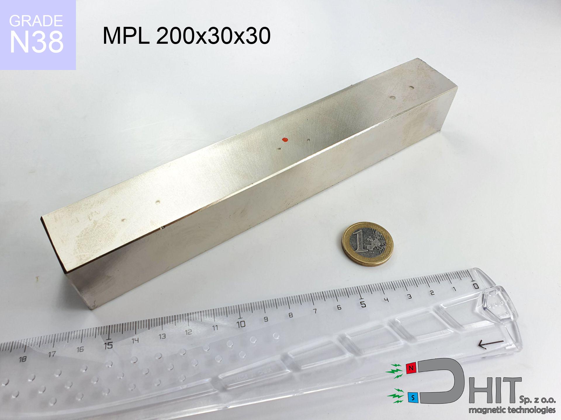
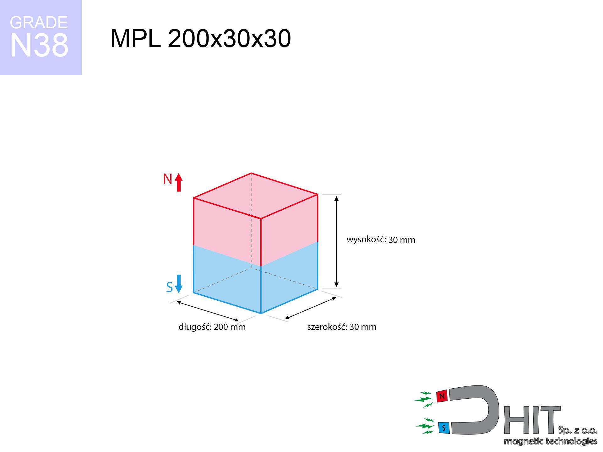
MPL 200x30x30 / N38 - lamellar magnet
lamellar magnet
Catalog no 020125
GTIN/EAN: 5906301811312
length
200 mm [±0,1 mm]
Width
30 mm [±0,1 mm]
Height
30 mm [±0,1 mm]
Weight
1350 g
Magnetization Direction
↑ axial
Load capacity
287.38 kg / 2819.19 N
Magnetic Induction
445.15 mT / 4451 Gs
Coating
[NiCuNi] Nickel
563.28 ZŁ with VAT / pcs + price for transport
457.95 ZŁ net + 23% VAT / pcs
bulk discounts:
Need more?
Call us now
+48 22 499 98 98
if you prefer get in touch using
contact form
through our site.
Force along with form of a neodymium magnet can be tested on our
online calculation tool.
Same-day processing for orders placed before 14:00.
Technical data of the product - MPL 200x30x30 / N38 - lamellar magnet
Specification / characteristics - MPL 200x30x30 / N38 - lamellar magnet
| properties | values |
|---|---|
| Cat. no. | 020125 |
| GTIN/EAN | 5906301811312 |
| Production/Distribution | Dhit sp. z o.o. |
| Country of origin | Poland / China / Germany |
| Customs code | 85059029 |
| length | 200 mm [±0,1 mm] |
| Width | 30 mm [±0,1 mm] |
| Height | 30 mm [±0,1 mm] |
| Weight | 1350 g |
| Magnetization Direction | ↑ axial |
| Load capacity ~ ? | 287.38 kg / 2819.19 N |
| Magnetic Induction ~ ? | 445.15 mT / 4451 Gs |
| Coating | [NiCuNi] Nickel |
| Manufacturing Tolerance | ±0.1 mm |
Magnetic properties of material N38
| properties | values | units |
|---|---|---|
| remenance Br [min. - max.] ? | 12.2-12.6 | kGs |
| remenance Br [min. - max.] ? | 1220-1260 | mT |
| coercivity bHc ? | 10.8-11.5 | kOe |
| coercivity bHc ? | 860-915 | kA/m |
| actual internal force iHc | ≥ 12 | kOe |
| actual internal force iHc | ≥ 955 | kA/m |
| energy density [min. - max.] ? | 36-38 | BH max MGOe |
| energy density [min. - max.] ? | 287-303 | BH max KJ/m |
| max. temperature ? | ≤ 80 | °C |
Physical properties of sintered neodymium magnets Nd2Fe14B at 20°C
| properties | values | units |
|---|---|---|
| Vickers hardness | ≥550 | Hv |
| Density | ≥7.4 | g/cm3 |
| Curie Temperature TC | 312 - 380 | °C |
| Curie Temperature TF | 593 - 716 | °F |
| Specific resistance | 150 | μΩ⋅cm |
| Bending strength | 250 | MPa |
| Compressive strength | 1000~1100 | MPa |
| Thermal expansion parallel (∥) to orientation (M) | (3-4) x 10-6 | °C-1 |
| Thermal expansion perpendicular (⊥) to orientation (M) | -(1-3) x 10-6 | °C-1 |
| Young's modulus | 1.7 x 10⁴ | kg/mm² |
Physical modeling of the magnet - report
Presented information are the result of a engineering simulation. Values are based on models for the material Nd2Fe14B. Real-world parameters might slightly deviate from the simulation results. Use these calculations as a preliminary roadmap when designing systems.
Table 1: Static force (pull vs gap) - interaction chart
MPL 200x30x30 / N38
| Distance (mm) | Induction (Gauss) / mT | Pull Force (kg/lbs/g/N) | Risk Status |
|---|---|---|---|
| 0 mm |
4451 Gs
445.1 mT
|
287.38 kg / 633.56 pounds
287380.0 g / 2819.2 N
|
crushing |
| 1 mm |
4241 Gs
424.1 mT
|
260.91 kg / 575.21 pounds
260910.0 g / 2559.5 N
|
crushing |
| 2 mm |
4028 Gs
402.8 mT
|
235.43 kg / 519.04 pounds
235433.0 g / 2309.6 N
|
crushing |
| 3 mm |
3818 Gs
381.8 mT
|
211.49 kg / 466.26 pounds
211490.2 g / 2074.7 N
|
crushing |
| 5 mm |
3412 Gs
341.2 mT
|
168.87 kg / 372.30 pounds
168870.4 g / 1656.6 N
|
crushing |
| 10 mm |
2539 Gs
253.9 mT
|
93.54 kg / 206.22 pounds
93539.2 g / 917.6 N
|
crushing |
| 15 mm |
1902 Gs
190.2 mT
|
52.48 kg / 115.70 pounds
52481.2 g / 514.8 N
|
crushing |
| 20 mm |
1457 Gs
145.7 mT
|
30.79 kg / 67.88 pounds
30789.8 g / 302.0 N
|
crushing |
| 30 mm |
920 Gs
92.0 mT
|
12.29 kg / 27.09 pounds
12288.2 g / 120.5 N
|
crushing |
| 50 mm |
456 Gs
45.6 mT
|
3.02 kg / 6.65 pounds
3016.4 g / 29.6 N
|
medium risk |
Table 2: Vertical capacity (wall)
MPL 200x30x30 / N38
| Distance (mm) | Friction coefficient | Pull Force (kg/lbs/g/N) |
|---|---|---|
| 0 mm | Stal (~0.2) |
57.48 kg / 126.71 pounds
57476.0 g / 563.8 N
|
| 1 mm | Stal (~0.2) |
52.18 kg / 115.04 pounds
52182.0 g / 511.9 N
|
| 2 mm | Stal (~0.2) |
47.09 kg / 103.81 pounds
47086.0 g / 461.9 N
|
| 3 mm | Stal (~0.2) |
42.30 kg / 93.25 pounds
42298.0 g / 414.9 N
|
| 5 mm | Stal (~0.2) |
33.77 kg / 74.46 pounds
33774.0 g / 331.3 N
|
| 10 mm | Stal (~0.2) |
18.71 kg / 41.24 pounds
18708.0 g / 183.5 N
|
| 15 mm | Stal (~0.2) |
10.50 kg / 23.14 pounds
10496.0 g / 103.0 N
|
| 20 mm | Stal (~0.2) |
6.16 kg / 13.58 pounds
6158.0 g / 60.4 N
|
| 30 mm | Stal (~0.2) |
2.46 kg / 5.42 pounds
2458.0 g / 24.1 N
|
| 50 mm | Stal (~0.2) |
0.60 kg / 1.33 pounds
604.0 g / 5.9 N
|
Table 3: Vertical assembly (shearing) - vertical pull
MPL 200x30x30 / N38
| Surface type | Friction coefficient / % Mocy | Max load (kg/lbs/g/N) |
|---|---|---|
| Raw steel |
µ = 0.3
30% Nominalnej Siły
|
86.21 kg / 190.07 pounds
86214.0 g / 845.8 N
|
| Painted steel (standard) |
µ = 0.2
20% Nominalnej Siły
|
57.48 kg / 126.71 pounds
57476.0 g / 563.8 N
|
| Oily/slippery steel |
µ = 0.1
10% Nominalnej Siły
|
28.74 kg / 63.36 pounds
28738.0 g / 281.9 N
|
| Magnet with anti-slip rubber |
µ = 0.5
50% Nominalnej Siły
|
143.69 kg / 316.78 pounds
143690.0 g / 1409.6 N
|
Table 4: Steel thickness (saturation) - power losses
MPL 200x30x30 / N38
| Steel thickness (mm) | % power | Real pull force (kg/lbs/g/N) |
|---|---|---|
| 0.5 mm |
|
9.58 kg / 21.12 pounds
9579.3 g / 94.0 N
|
| 1 mm |
|
23.95 kg / 52.80 pounds
23948.3 g / 234.9 N
|
| 2 mm |
|
47.90 kg / 105.59 pounds
47896.7 g / 469.9 N
|
| 3 mm |
|
71.85 kg / 158.39 pounds
71845.0 g / 704.8 N
|
| 5 mm |
|
119.74 kg / 263.98 pounds
119741.7 g / 1174.7 N
|
| 10 mm |
|
239.48 kg / 527.97 pounds
239483.3 g / 2349.3 N
|
| 11 mm |
|
263.43 kg / 580.77 pounds
263431.7 g / 2584.3 N
|
| 12 mm |
|
287.38 kg / 633.56 pounds
287380.0 g / 2819.2 N
|
Table 5: Working in heat (stability) - thermal limit
MPL 200x30x30 / N38
| Ambient temp. (°C) | Power loss | Remaining pull (kg/lbs/g/N) | Status |
|---|---|---|---|
| 20 °C | 0.0% |
287.38 kg / 633.56 pounds
287380.0 g / 2819.2 N
|
OK |
| 40 °C | -2.2% |
281.06 kg / 619.63 pounds
281057.6 g / 2757.2 N
|
OK |
| 60 °C | -4.4% |
274.74 kg / 605.69 pounds
274735.3 g / 2695.2 N
|
|
| 80 °C | -6.6% |
268.41 kg / 591.75 pounds
268412.9 g / 2633.1 N
|
|
| 100 °C | -28.8% |
204.61 kg / 451.10 pounds
204614.6 g / 2007.3 N
|
Table 6: Magnet-Magnet interaction (attraction) - forces in the system
MPL 200x30x30 / N38
| Gap (mm) | Attraction (kg/lbs) (N-S) | Shear Force (kg/lbs/g/N) | Repulsion (kg/lbs) (N-N) |
|---|---|---|---|
| 0 mm |
732.71 kg / 1615.35 pounds
5 371 Gs
|
109.91 kg / 242.30 pounds
109907 g / 1078.2 N
|
N/A |
| 1 mm |
698.96 kg / 1540.95 pounds
8 694 Gs
|
104.84 kg / 231.14 pounds
104845 g / 1028.5 N
|
629.07 kg / 1386.85 pounds
~0 Gs
|
| 2 mm |
665.22 kg / 1466.57 pounds
8 481 Gs
|
99.78 kg / 219.99 pounds
99784 g / 978.9 N
|
598.70 kg / 1319.91 pounds
~0 Gs
|
| 3 mm |
632.29 kg / 1393.97 pounds
8 269 Gs
|
94.84 kg / 209.10 pounds
94844 g / 930.4 N
|
569.07 kg / 1254.57 pounds
~0 Gs
|
| 5 mm |
569.22 kg / 1254.92 pounds
7 846 Gs
|
85.38 kg / 188.24 pounds
85383 g / 837.6 N
|
512.30 kg / 1129.42 pounds
~0 Gs
|
| 10 mm |
430.56 kg / 949.22 pounds
6 823 Gs
|
64.58 kg / 142.38 pounds
64584 g / 633.6 N
|
387.50 kg / 854.29 pounds
~0 Gs
|
| 20 mm |
238.49 kg / 525.78 pounds
5 078 Gs
|
35.77 kg / 78.87 pounds
35774 g / 350.9 N
|
214.64 kg / 473.20 pounds
~0 Gs
|
| 50 mm |
48.45 kg / 106.82 pounds
2 289 Gs
|
7.27 kg / 16.02 pounds
7268 g / 71.3 N
|
43.61 kg / 96.13 pounds
~0 Gs
|
| 60 mm |
31.33 kg / 69.07 pounds
1 841 Gs
|
4.70 kg / 10.36 pounds
4700 g / 46.1 N
|
28.20 kg / 62.16 pounds
~0 Gs
|
| 70 mm |
21.09 kg / 46.49 pounds
1 510 Gs
|
3.16 kg / 6.97 pounds
3163 g / 31.0 N
|
18.98 kg / 41.84 pounds
~0 Gs
|
| 80 mm |
14.67 kg / 32.35 pounds
1 260 Gs
|
2.20 kg / 4.85 pounds
2201 g / 21.6 N
|
13.21 kg / 29.12 pounds
~0 Gs
|
| 90 mm |
10.50 kg / 23.15 pounds
1 066 Gs
|
1.58 kg / 3.47 pounds
1575 g / 15.5 N
|
9.45 kg / 20.83 pounds
~0 Gs
|
| 100 mm |
7.69 kg / 16.95 pounds
912 Gs
|
1.15 kg / 2.54 pounds
1154 g / 11.3 N
|
6.92 kg / 15.26 pounds
~0 Gs
|
Table 7: Hazards (electronics) - warnings
MPL 200x30x30 / N38
| Object / Device | Limit (Gauss) / mT | Safe distance |
|---|---|---|
| Pacemaker | 5 Gs (0.5 mT) | 39.5 cm |
| Hearing aid | 10 Gs (1.0 mT) | 30.5 cm |
| Timepiece | 20 Gs (2.0 mT) | 23.5 cm |
| Phone / Smartphone | 40 Gs (4.0 mT) | 18.0 cm |
| Remote | 50 Gs (5.0 mT) | 16.5 cm |
| Payment card | 400 Gs (40.0 mT) | 5.5 cm |
| HDD hard drive | 600 Gs (60.0 mT) | 4.5 cm |
Table 8: Collisions (kinetic energy) - collision effects
MPL 200x30x30 / N38
| Start from (mm) | Speed (km/h) | Energy (J) | Predicted outcome |
|---|---|---|---|
| 10 mm |
17.45 km/h
(4.85 m/s)
|
15.86 J | |
| 30 mm |
26.16 km/h
(7.27 m/s)
|
35.64 J | |
| 50 mm |
33.12 km/h
(9.20 m/s)
|
57.12 J | |
| 100 mm |
46.56 km/h
(12.93 m/s)
|
112.90 J |
Table 9: Coating parameters (durability)
MPL 200x30x30 / N38
| Technical parameter | Value / Description |
|---|---|
| Coating type | [NiCuNi] Nickel |
| Layer structure | Nickel - Copper - Nickel |
| Layer thickness | 10-20 µm |
| Salt spray test (SST) ? | 24 h |
| Recommended environment | Indoors only (dry) |
Table 10: Electrical data (Flux)
MPL 200x30x30 / N38
| Parameter | Value | SI Unit / Description |
|---|---|---|
| Magnetic Flux | 221 734 Mx | 2217.3 µWb |
| Pc Coefficient | 0.45 | Low (Flat) |
Table 11: Submerged application
MPL 200x30x30 / N38
| Environment | Effective steel pull | Effect |
|---|---|---|
| Air (land) | 287.38 kg | Standard |
| Water (riverbed) |
329.05 kg
(+41.67 kg buoyancy gain)
|
+14.5% |
1. Shear force
*Warning: On a vertical surface, the magnet holds merely a fraction of its max power.
2. Plate thickness effect
*Thin metal sheet (e.g. 0.5mm PC case) significantly reduces the holding force.
3. Power loss vs temp
*For N38 grade, the critical limit is 80°C.
4. Demagnetization curve and operating point (B-H)
chart generated for the permeance coefficient Pc (Permeance Coefficient) = 0.45
This simulation demonstrates the magnetic stability of the selected magnet under specific geometric conditions. The solid red line represents the demagnetization curve (material potential), while the dashed blue line is the load line based on the magnet's geometry. The Pc (Permeance Coefficient), also known as the load line slope, is a dimensionless value that describes the relationship between the magnet's shape and its magnetic stability. The intersection of these two lines (the black dot) is the operating point — it determines the actual magnetic flux density generated by the magnet in this specific configuration. A higher Pc value means the magnet is more 'slender' (tall relative to its area), resulting in a higher operating point and better resistance to irreversible demagnetization caused by external fields or temperature. A value of 0.42 is relatively low (typical for flat magnets), meaning the operating point is closer to the 'knee' of the curve — caution is advised when operating at temperatures near the maximum limit to avoid strength loss.
Material specification
| iron (Fe) | 64% – 68% |
| neodymium (Nd) | 29% – 32% |
| boron (B) | 1.1% – 1.2% |
| dysprosium (Dy) | 0.5% – 2.0% |
| coating (Ni-Cu-Ni) | < 0.05% |
Environmental data
| recyclability (EoL) | 100% |
| recycled raw materials | ~10% (pre-cons) |
| carbon footprint | low / zredukowany |
| waste code (EWC) | 16 02 16 |
Other deals
![HH 25x7.7 [M5] / N38 - through hole magnetic holder](https://cdn3.dhit.pl/graphics/products/hh-25x7.7-m5-pov.jpg "HH 25x7.7 [M5] / N38 - through hole magnetic holder")
![UMGZ 16x13x5 [M4] GZ / N38 - magnetic holder external thread](https://cdn3.dhit.pl/graphics/products/um-16x13x5-m4-gz-cor.jpg "UMGZ 16x13x5 [M4] GZ / N38 - magnetic holder external thread")


Advantages as well as disadvantages of Nd2Fe14B magnets.
Benefits
- They retain magnetic properties for around ten years – the loss is just ~1% (according to analyses),
- They have excellent resistance to magnetic field loss when exposed to external fields,
- In other words, due to the reflective surface of gold, the element looks attractive,
- Magnetic induction on the top side of the magnet is strong,
- Thanks to resistance to high temperature, they are capable of working (depending on the form) even at temperatures up to 230°C and higher...
- Possibility of individual shaping as well as adapting to complex requirements,
- Wide application in innovative solutions – they are used in hard drives, electric motors, precision medical tools, also industrial machines.
- Compactness – despite small sizes they offer powerful magnetic field, making them ideal for precision applications
Cons
- They are prone to damage upon too strong impacts. To avoid cracks, it is worth securing magnets in special housings. Such protection not only protects the magnet but also improves its resistance to damage
- When exposed to high temperature, neodymium magnets experience a drop in strength. Often, when the temperature exceeds 80°C, their strength decreases (depending on the size, as well as shape of the magnet). For those who need magnets for extreme conditions, we offer [AH] versions withstanding up to 230°C
- Due to the susceptibility of magnets to corrosion in a humid environment, we recommend using waterproof magnets made of rubber, plastic or other material immune to moisture, in case of application outdoors
- Due to limitations in creating threads and complicated forms in magnets, we propose using casing - magnetic holder.
- Potential hazard related to microscopic parts of magnets can be dangerous, in case of ingestion, which gains importance in the aspect of protecting the youngest. Additionally, tiny parts of these devices are able to disrupt the diagnostic process medical after entering the body.
- Due to complex production process, their price is higher than average,
Lifting parameters
Breakaway strength of the magnet in ideal conditions – what contributes to it?
- using a base made of mild steel, serving as a magnetic yoke
- possessing a thickness of minimum 10 mm to avoid saturation
- with a surface perfectly flat
- with direct contact (no paint)
- during pulling in a direction vertical to the mounting surface
- in stable room temperature
Key elements affecting lifting force
- Gap between magnet and steel – every millimeter of distance (caused e.g. by veneer or unevenness) drastically reduces the pulling force, often by half at just 0.5 mm.
- Force direction – catalog parameter refers to pulling vertically. When slipping, the magnet exhibits much less (often approx. 20-30% of maximum force).
- Substrate thickness – for full efficiency, the steel must be adequately massive. Thin sheet restricts the attraction force (the magnet "punches through" it).
- Material type – ideal substrate is pure iron steel. Cast iron may generate lower lifting capacity.
- Plate texture – ground elements ensure maximum contact, which improves force. Uneven metal weaken the grip.
- Temperature influence – hot environment reduces magnetic field. Exceeding the limit temperature can permanently damage the magnet.
Holding force was tested on a smooth steel plate of 20 mm thickness, when the force acted perpendicularly, whereas under parallel forces the load capacity is reduced by as much as 5 times. Additionally, even a minimal clearance between the magnet’s surface and the plate lowers the holding force.
Safe handling of NdFeB magnets
Do not underestimate power
Before starting, check safety instructions. Sudden snapping can destroy the magnet or hurt your hand. Be predictive.
Pinching danger
Danger of trauma: The pulling power is so great that it can cause hematomas, pinching, and even bone fractures. Protective gloves are recommended.
Electronic hazard
Data protection: Strong magnets can ruin payment cards and sensitive devices (heart implants, hearing aids, timepieces).
Risk of cracking
Watch out for shards. Magnets can fracture upon uncontrolled impact, launching shards into the air. Eye protection is mandatory.
Product not for children
Adult use only. Tiny parts pose a choking risk, leading to serious injuries. Keep away from kids and pets.
Life threat
Life threat: Neodymium magnets can deactivate heart devices and defibrillators. Stay away if you have medical devices.
Allergy Warning
Certain individuals experience a sensitization to Ni, which is the typical protective layer for NdFeB magnets. Prolonged contact can result in skin redness. We recommend use safety gloves.
Machining danger
Powder generated during machining of magnets is self-igniting. Do not drill into magnets unless you are an expert.
Maximum temperature
Do not overheat. NdFeB magnets are susceptible to temperature. If you need resistance above 80°C, inquire about special high-temperature series (H, SH, UH).
Keep away from electronics
A strong magnetic field negatively affects the operation of magnetometers in phones and navigation systems. Maintain magnets near a smartphone to avoid breaking the sensors.
Tabela kosztu i czasu dostawy
Płatność przed wysyłką:

GLS kurier
Przesyłka będzie u Ciebie za 2-3 dni
14.99 ZŁ

InPost Paczkomaty 24/7
Przesyłka będzie u Ciebie za 1-2 dni
12.30 ZŁ
Płatność przy odbiorze (pobranie):
GLS kurier
Przesyłka będzie u Ciebie za 1-2 dni
23.00 ZŁ
Rate the product
Your rating