

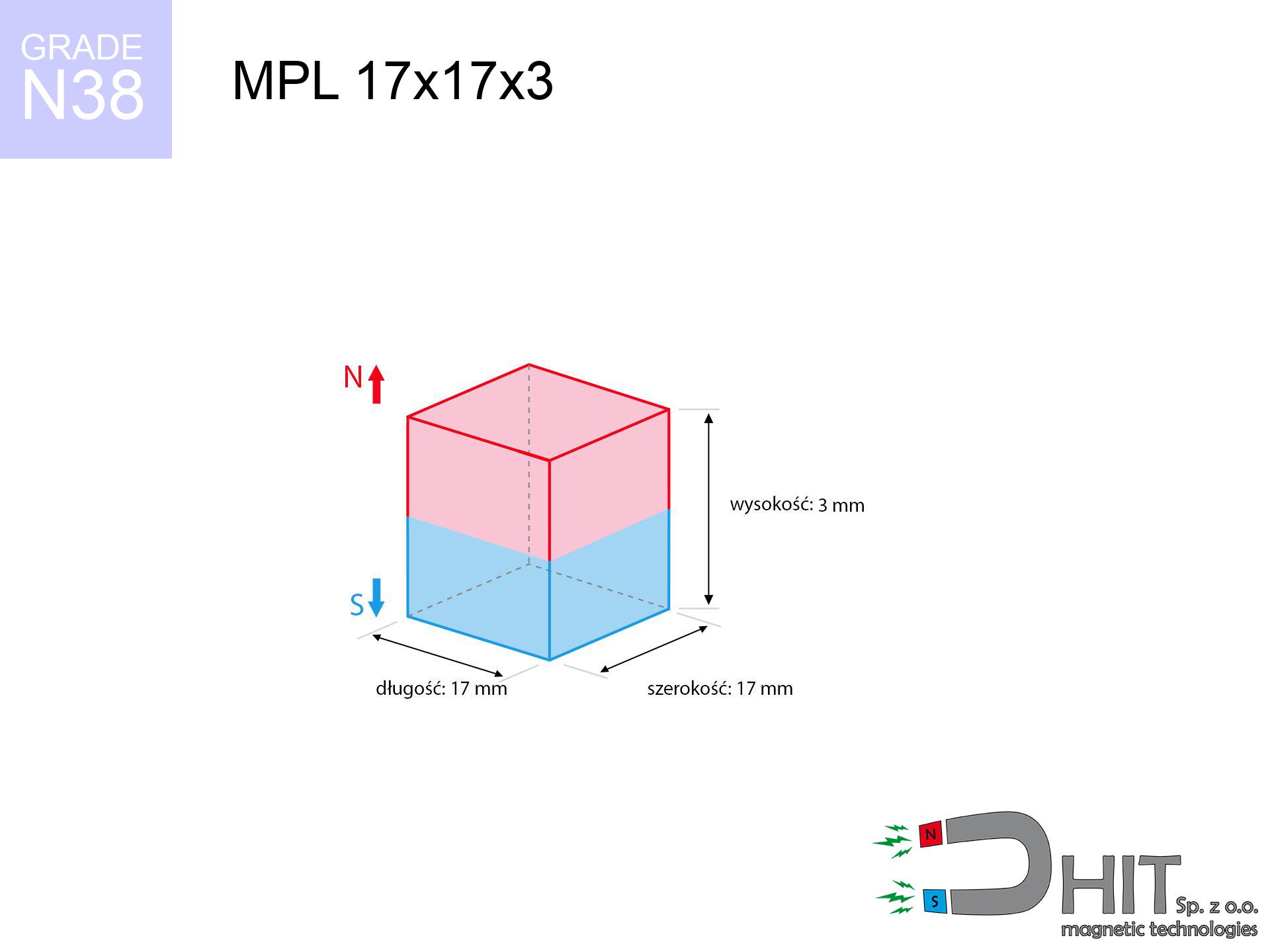
MPL 17x17x3 / N38 - lamellar magnet
lamellar magnet
Catalog no 020124
GTIN/EAN: 5906301811305
length
17 mm [±0,1 mm]
Width
17 mm [±0,1 mm]
Height
3 mm [±0,1 mm]
Weight
6.5 g
Magnetization Direction
↑ axial
Load capacity
3.22 kg / 31.54 N
Magnetic Induction
187.48 mT / 1875 Gs
Coating
[NiCuNi] Nickel
4.71 ZŁ with VAT / pcs + price for transport
3.83 ZŁ net + 23% VAT / pcs
bulk discounts:
Need more?
Contact us by phone
+48 22 499 98 98
otherwise let us know by means of
contact form
the contact form page.
Force along with appearance of magnets can be checked using our
our magnetic calculator.
Same-day shipping for orders placed before 14:00.
Product card - MPL 17x17x3 / N38 - lamellar magnet
Specification / characteristics - MPL 17x17x3 / N38 - lamellar magnet
| properties | values |
|---|---|
| Cat. no. | 020124 |
| GTIN/EAN | 5906301811305 |
| Production/Distribution | Dhit sp. z o.o. |
| Country of origin | Poland / China / Germany |
| Customs code | 85059029 |
| length | 17 mm [±0,1 mm] |
| Width | 17 mm [±0,1 mm] |
| Height | 3 mm [±0,1 mm] |
| Weight | 6.5 g |
| Magnetization Direction | ↑ axial |
| Load capacity ~ ? | 3.22 kg / 31.54 N |
| Magnetic Induction ~ ? | 187.48 mT / 1875 Gs |
| Coating | [NiCuNi] Nickel |
| Manufacturing Tolerance | ±0.1 mm |
Magnetic properties of material N38
| properties | values | units |
|---|---|---|
| remenance Br [min. - max.] ? | 12.2-12.6 | kGs |
| remenance Br [min. - max.] ? | 1220-1260 | mT |
| coercivity bHc ? | 10.8-11.5 | kOe |
| coercivity bHc ? | 860-915 | kA/m |
| actual internal force iHc | ≥ 12 | kOe |
| actual internal force iHc | ≥ 955 | kA/m |
| energy density [min. - max.] ? | 36-38 | BH max MGOe |
| energy density [min. - max.] ? | 287-303 | BH max KJ/m |
| max. temperature ? | ≤ 80 | °C |
Physical properties of sintered neodymium magnets Nd2Fe14B at 20°C
| properties | values | units |
|---|---|---|
| Vickers hardness | ≥550 | Hv |
| Density | ≥7.4 | g/cm3 |
| Curie Temperature TC | 312 - 380 | °C |
| Curie Temperature TF | 593 - 716 | °F |
| Specific resistance | 150 | μΩ⋅cm |
| Bending strength | 250 | MPa |
| Compressive strength | 1000~1100 | MPa |
| Thermal expansion parallel (∥) to orientation (M) | (3-4) x 10-6 | °C-1 |
| Thermal expansion perpendicular (⊥) to orientation (M) | -(1-3) x 10-6 | °C-1 |
| Young's modulus | 1.7 x 10⁴ | kg/mm² |
Technical analysis of the product - report
These data represent the direct effect of a engineering calculation. Values rely on models for the class Nd2Fe14B. Actual conditions may differ. Please consider these data as a preliminary roadmap when designing systems.
Table 1: Static pull force (pull vs distance) - power drop
MPL 17x17x3 / N38
| Distance (mm) | Induction (Gauss) / mT | Pull Force (kg/lbs/g/N) | Risk Status |
|---|---|---|---|
| 0 mm |
1874 Gs
187.4 mT
|
3.22 kg / 7.10 LBS
3220.0 g / 31.6 N
|
strong |
| 1 mm |
1761 Gs
176.1 mT
|
2.84 kg / 6.27 LBS
2842.9 g / 27.9 N
|
strong |
| 2 mm |
1610 Gs
161.0 mT
|
2.38 kg / 5.24 LBS
2376.8 g / 23.3 N
|
strong |
| 3 mm |
1440 Gs
144.0 mT
|
1.90 kg / 4.19 LBS
1901.0 g / 18.6 N
|
safe |
| 5 mm |
1099 Gs
109.9 mT
|
1.11 kg / 2.44 LBS
1107.5 g / 10.9 N
|
safe |
| 10 mm |
508 Gs
50.8 mT
|
0.24 kg / 0.52 LBS
236.4 g / 2.3 N
|
safe |
| 15 mm |
245 Gs
24.5 mT
|
0.06 kg / 0.12 LBS
55.2 g / 0.5 N
|
safe |
| 20 mm |
131 Gs
13.1 mT
|
0.02 kg / 0.03 LBS
15.7 g / 0.2 N
|
safe |
| 30 mm |
48 Gs
4.8 mT
|
0.00 kg / 0.00 LBS
2.1 g / 0.0 N
|
safe |
| 50 mm |
12 Gs
1.2 mT
|
0.00 kg / 0.00 LBS
0.1 g / 0.0 N
|
safe |
Table 2: Sliding hold (vertical surface)
MPL 17x17x3 / N38
| Distance (mm) | Friction coefficient | Pull Force (kg/lbs/g/N) |
|---|---|---|
| 0 mm | Stal (~0.2) |
0.64 kg / 1.42 LBS
644.0 g / 6.3 N
|
| 1 mm | Stal (~0.2) |
0.57 kg / 1.25 LBS
568.0 g / 5.6 N
|
| 2 mm | Stal (~0.2) |
0.48 kg / 1.05 LBS
476.0 g / 4.7 N
|
| 3 mm | Stal (~0.2) |
0.38 kg / 0.84 LBS
380.0 g / 3.7 N
|
| 5 mm | Stal (~0.2) |
0.22 kg / 0.49 LBS
222.0 g / 2.2 N
|
| 10 mm | Stal (~0.2) |
0.05 kg / 0.11 LBS
48.0 g / 0.5 N
|
| 15 mm | Stal (~0.2) |
0.01 kg / 0.03 LBS
12.0 g / 0.1 N
|
| 20 mm | Stal (~0.2) |
0.00 kg / 0.01 LBS
4.0 g / 0.0 N
|
| 30 mm | Stal (~0.2) |
0.00 kg / 0.00 LBS
0.0 g / 0.0 N
|
| 50 mm | Stal (~0.2) |
0.00 kg / 0.00 LBS
0.0 g / 0.0 N
|
Table 3: Wall mounting (shearing) - vertical pull
MPL 17x17x3 / N38
| Surface type | Friction coefficient / % Mocy | Max load (kg/lbs/g/N) |
|---|---|---|
| Raw steel |
µ = 0.3
30% Nominalnej Siły
|
0.97 kg / 2.13 LBS
966.0 g / 9.5 N
|
| Painted steel (standard) |
µ = 0.2
20% Nominalnej Siły
|
0.64 kg / 1.42 LBS
644.0 g / 6.3 N
|
| Oily/slippery steel |
µ = 0.1
10% Nominalnej Siły
|
0.32 kg / 0.71 LBS
322.0 g / 3.2 N
|
| Magnet with anti-slip rubber |
µ = 0.5
50% Nominalnej Siły
|
1.61 kg / 3.55 LBS
1610.0 g / 15.8 N
|
Table 4: Steel thickness (substrate influence) - power losses
MPL 17x17x3 / N38
| Steel thickness (mm) | % power | Real pull force (kg/lbs/g/N) |
|---|---|---|
| 0.5 mm |
|
0.32 kg / 0.71 LBS
322.0 g / 3.2 N
|
| 1 mm |
|
0.81 kg / 1.77 LBS
805.0 g / 7.9 N
|
| 2 mm |
|
1.61 kg / 3.55 LBS
1610.0 g / 15.8 N
|
| 3 mm |
|
2.42 kg / 5.32 LBS
2415.0 g / 23.7 N
|
| 5 mm |
|
3.22 kg / 7.10 LBS
3220.0 g / 31.6 N
|
| 10 mm |
|
3.22 kg / 7.10 LBS
3220.0 g / 31.6 N
|
| 11 mm |
|
3.22 kg / 7.10 LBS
3220.0 g / 31.6 N
|
| 12 mm |
|
3.22 kg / 7.10 LBS
3220.0 g / 31.6 N
|
Table 5: Thermal stability (stability) - thermal limit
MPL 17x17x3 / N38
| Ambient temp. (°C) | Power loss | Remaining pull (kg/lbs/g/N) | Status |
|---|---|---|---|
| 20 °C | 0.0% |
3.22 kg / 7.10 LBS
3220.0 g / 31.6 N
|
OK |
| 40 °C | -2.2% |
3.15 kg / 6.94 LBS
3149.2 g / 30.9 N
|
OK |
| 60 °C | -4.4% |
3.08 kg / 6.79 LBS
3078.3 g / 30.2 N
|
|
| 80 °C | -6.6% |
3.01 kg / 6.63 LBS
3007.5 g / 29.5 N
|
|
| 100 °C | -28.8% |
2.29 kg / 5.05 LBS
2292.6 g / 22.5 N
|
Table 6: Two magnets (attraction) - field collision
MPL 17x17x3 / N38
| Gap (mm) | Attraction (kg/lbs) (N-S) | Shear Force (kg/lbs/g/N) | Repulsion (kg/lbs) (N-N) |
|---|---|---|---|
| 0 mm |
6.26 kg / 13.80 LBS
3 313 Gs
|
0.94 kg / 2.07 LBS
939 g / 9.2 N
|
N/A |
| 1 mm |
5.93 kg / 13.07 LBS
3 648 Gs
|
0.89 kg / 1.96 LBS
889 g / 8.7 N
|
5.33 kg / 11.76 LBS
~0 Gs
|
| 2 mm |
5.53 kg / 12.19 LBS
3 523 Gs
|
0.83 kg / 1.83 LBS
829 g / 8.1 N
|
4.97 kg / 10.97 LBS
~0 Gs
|
| 3 mm |
5.08 kg / 11.21 LBS
3 379 Gs
|
0.76 kg / 1.68 LBS
763 g / 7.5 N
|
4.58 kg / 10.09 LBS
~0 Gs
|
| 5 mm |
4.15 kg / 9.16 LBS
3 053 Gs
|
0.62 kg / 1.37 LBS
623 g / 6.1 N
|
3.74 kg / 8.24 LBS
~0 Gs
|
| 10 mm |
2.15 kg / 4.75 LBS
2 199 Gs
|
0.32 kg / 0.71 LBS
323 g / 3.2 N
|
1.94 kg / 4.27 LBS
~0 Gs
|
| 20 mm |
0.46 kg / 1.01 LBS
1 016 Gs
|
0.07 kg / 0.15 LBS
69 g / 0.7 N
|
0.41 kg / 0.91 LBS
~0 Gs
|
| 50 mm |
0.01 kg / 0.02 LBS
153 Gs
|
0.00 kg / 0.00 LBS
2 g / 0.0 N
|
0.01 kg / 0.02 LBS
~0 Gs
|
| 60 mm |
0.00 kg / 0.01 LBS
96 Gs
|
0.00 kg / 0.00 LBS
1 g / 0.0 N
|
0.00 kg / 0.00 LBS
~0 Gs
|
| 70 mm |
0.00 kg / 0.00 LBS
64 Gs
|
0.00 kg / 0.00 LBS
0 g / 0.0 N
|
0.00 kg / 0.00 LBS
~0 Gs
|
| 80 mm |
0.00 kg / 0.00 LBS
44 Gs
|
0.00 kg / 0.00 LBS
0 g / 0.0 N
|
0.00 kg / 0.00 LBS
~0 Gs
|
| 90 mm |
0.00 kg / 0.00 LBS
32 Gs
|
0.00 kg / 0.00 LBS
0 g / 0.0 N
|
0.00 kg / 0.00 LBS
~0 Gs
|
| 100 mm |
0.00 kg / 0.00 LBS
24 Gs
|
0.00 kg / 0.00 LBS
0 g / 0.0 N
|
0.00 kg / 0.00 LBS
~0 Gs
|
Table 7: Hazards (electronics) - warnings
MPL 17x17x3 / N38
| Object / Device | Limit (Gauss) / mT | Safe distance |
|---|---|---|
| Pacemaker | 5 Gs (0.5 mT) | 7.0 cm |
| Hearing aid | 10 Gs (1.0 mT) | 5.5 cm |
| Timepiece | 20 Gs (2.0 mT) | 4.5 cm |
| Phone / Smartphone | 40 Gs (4.0 mT) | 3.5 cm |
| Car key | 50 Gs (5.0 mT) | 3.0 cm |
| Payment card | 400 Gs (40.0 mT) | 1.5 cm |
| HDD hard drive | 600 Gs (60.0 mT) | 1.0 cm |
Table 8: Collisions (cracking risk) - warning
MPL 17x17x3 / N38
| Start from (mm) | Speed (km/h) | Energy (J) | Predicted outcome |
|---|---|---|---|
| 10 mm |
23.45 km/h
(6.52 m/s)
|
0.14 J | |
| 30 mm |
38.89 km/h
(10.80 m/s)
|
0.38 J | |
| 50 mm |
50.19 km/h
(13.94 m/s)
|
0.63 J | |
| 100 mm |
70.98 km/h
(19.72 m/s)
|
1.26 J |
Table 9: Coating parameters (durability)
MPL 17x17x3 / N38
| Technical parameter | Value / Description |
|---|---|
| Coating type | [NiCuNi] Nickel |
| Layer structure | Nickel - Copper - Nickel |
| Layer thickness | 10-20 µm |
| Salt spray test (SST) ? | 24 h |
| Recommended environment | Indoors only (dry) |
Table 10: Construction data (Flux)
MPL 17x17x3 / N38
| Parameter | Value | SI Unit / Description |
|---|---|---|
| Magnetic Flux | 6 509 Mx | 65.1 µWb |
| Pc Coefficient | 0.23 | Low (Flat) |
Table 11: Submerged application
MPL 17x17x3 / N38
| Environment | Effective steel pull | Effect |
|---|---|---|
| Air (land) | 3.22 kg | Standard |
| Water (riverbed) |
3.69 kg
(+0.47 kg buoyancy gain)
|
+14.5% |
1. Shear force
*Warning: On a vertical wall, the magnet holds just ~20% of its perpendicular strength.
2. Steel thickness impact
*Thin metal sheet (e.g. computer case) drastically reduces the holding force.
3. Heat tolerance
*For standard magnets, the max working temp is 80°C.
4. Demagnetization curve and operating point (B-H)
chart generated for the permeance coefficient Pc (Permeance Coefficient) = 0.23
The chart above illustrates the magnetic characteristics of the material within the second quadrant of the hysteresis loop. The solid red line represents the demagnetization curve (material potential), while the dashed blue line is the load line based on the magnet's geometry. The Pc (Permeance Coefficient), also known as the load line slope, is a dimensionless value that describes the relationship between the magnet's shape and its magnetic stability. The intersection of these two lines (the black dot) is the operating point — it determines the actual magnetic flux density generated by the magnet in this specific configuration. A higher Pc value means the magnet is more 'slender' (tall relative to its area), resulting in a higher operating point and better resistance to irreversible demagnetization caused by external fields or temperature. A value of 0.42 is relatively low (typical for flat magnets), meaning the operating point is closer to the 'knee' of the curve — caution is advised when operating at temperatures near the maximum limit to avoid strength loss.
Elemental analysis
| iron (Fe) | 64% – 68% |
| neodymium (Nd) | 29% – 32% |
| boron (B) | 1.1% – 1.2% |
| dysprosium (Dy) | 0.5% – 2.0% |
| coating (Ni-Cu-Ni) | < 0.05% |
Sustainability
| recyclability (EoL) | 100% |
| recycled raw materials | ~10% (pre-cons) |
| carbon footprint | low / zredukowany |
| waste code (EWC) | 16 02 16 |
Check out also proposals


![SM 19x225 [2xM6] / N50 - magnetic separator](https://cdn3.dhit.pl/graphics/products/sm-19x225-2xm6-jis.jpg "SM 19x225 [2xM6] / N50 - magnetic separator")

Pros and cons of Nd2Fe14B magnets.
Benefits
- They retain magnetic properties for around ten years – the drop is just ~1% (based on simulations),
- Magnets very well defend themselves against demagnetization caused by foreign field sources,
- Thanks to the elegant finish, the layer of nickel, gold, or silver-plated gives an aesthetic appearance,
- Neodymium magnets ensure maximum magnetic induction on a small area, which increases force concentration,
- Neodymium magnets are characterized by very high magnetic induction on the magnet surface and are able to act (depending on the shape) even at a temperature of 230°C or more...
- In view of the ability of free molding and customization to specialized needs, NdFeB magnets can be created in a variety of shapes and sizes, which amplifies use scope,
- Huge importance in modern technologies – they find application in hard drives, electric motors, medical devices, also multitasking production systems.
- Compactness – despite small sizes they offer powerful magnetic field, making them ideal for precision applications
Cons
- Susceptibility to cracking is one of their disadvantages. Upon intense impact they can fracture. We advise keeping them in a steel housing, which not only protects them against impacts but also raises their durability
- NdFeB magnets lose force when exposed to high temperatures. After reaching 80°C, many of them experience permanent drop of power (a factor is the shape and dimensions of the magnet). We offer magnets specially adapted to work at temperatures up to 230°C marked [AH], which are extremely resistant to heat
- Due to the susceptibility of magnets to corrosion in a humid environment, we suggest using waterproof magnets made of rubber, plastic or other material immune to moisture, when using outdoors
- Limited ability of creating nuts in the magnet and complex shapes - preferred is a housing - magnet mounting.
- Possible danger related to microscopic parts of magnets can be dangerous, if swallowed, which gains importance in the context of child safety. Furthermore, small elements of these devices are able to disrupt the diagnostic process medical after entering the body.
- Higher cost of purchase is a significant factor to consider compared to ceramic magnets, especially in budget applications
Holding force characteristics
Maximum holding power of the magnet – what affects it?
- on a base made of structural steel, perfectly concentrating the magnetic field
- possessing a thickness of minimum 10 mm to avoid saturation
- with an ideally smooth contact surface
- with direct contact (without paint)
- under axial force vector (90-degree angle)
- at ambient temperature room level
Magnet lifting force in use – key factors
- Distance – existence of foreign body (paint, dirt, gap) acts as an insulator, which lowers capacity steeply (even by 50% at 0.5 mm).
- Load vector – maximum parameter is available only during pulling at a 90° angle. The shear force of the magnet along the plate is standardly several times smaller (approx. 1/5 of the lifting capacity).
- Plate thickness – too thin steel does not close the flux, causing part of the power to be wasted to the other side.
- Chemical composition of the base – mild steel gives the best results. Higher carbon content lower magnetic permeability and lifting capacity.
- Surface finish – full contact is obtained only on polished steel. Rough texture create air cushions, reducing force.
- Temperature influence – hot environment weakens magnetic field. Too high temperature can permanently damage the magnet.
Holding force was checked on a smooth steel plate of 20 mm thickness, when a perpendicular force was applied, in contrast under shearing force the load capacity is reduced by as much as 5 times. In addition, even a minimal clearance between the magnet and the plate lowers the holding force.
Warnings
Swallowing risk
Absolutely keep magnets away from children. Ingestion danger is significant, and the consequences of magnets connecting inside the body are tragic.
Avoid contact if allergic
Medical facts indicate that the nickel plating (standard magnet coating) is a strong allergen. If you have an allergy, refrain from touching magnets with bare hands and choose versions in plastic housing.
Data carriers
Avoid bringing magnets close to a wallet, laptop, or TV. The magnetism can irreversibly ruin these devices and wipe information from cards.
Power loss in heat
Standard neodymium magnets (N-type) lose magnetization when the temperature goes above 80°C. The loss of strength is permanent.
ICD Warning
Life threat: Neodymium magnets can deactivate heart devices and defibrillators. Do not approach if you have electronic implants.
Respect the power
Handle with care. Neodymium magnets act from a distance and connect with massive power, often faster than you can move away.
Crushing force
Big blocks can smash fingers instantly. Under no circumstances put your hand between two attracting surfaces.
Dust explosion hazard
Mechanical processing of NdFeB material poses a fire risk. Neodymium dust oxidizes rapidly with oxygen and is hard to extinguish.
Magnet fragility
Neodymium magnets are ceramic materials, meaning they are fragile like glass. Impact of two magnets will cause them shattering into small pieces.
Threat to navigation
GPS units and smartphones are extremely sensitive to magnetic fields. Direct contact with a strong magnet can decalibrate the internal compass in your phone.
Tabela kosztu i czasu dostawy
Płatność przed wysyłką:

GLS kurier
Przesyłka będzie u Ciebie za 2-3 dni
14.99 ZŁ

InPost Paczkomaty 24/7
Przesyłka będzie u Ciebie za 1-2 dni
12.30 ZŁ
Płatność przy odbiorze (pobranie):
GLS kurier
Przesyłka będzie u Ciebie za 1-2 dni
23.00 ZŁ
Rate the product
Your rating