

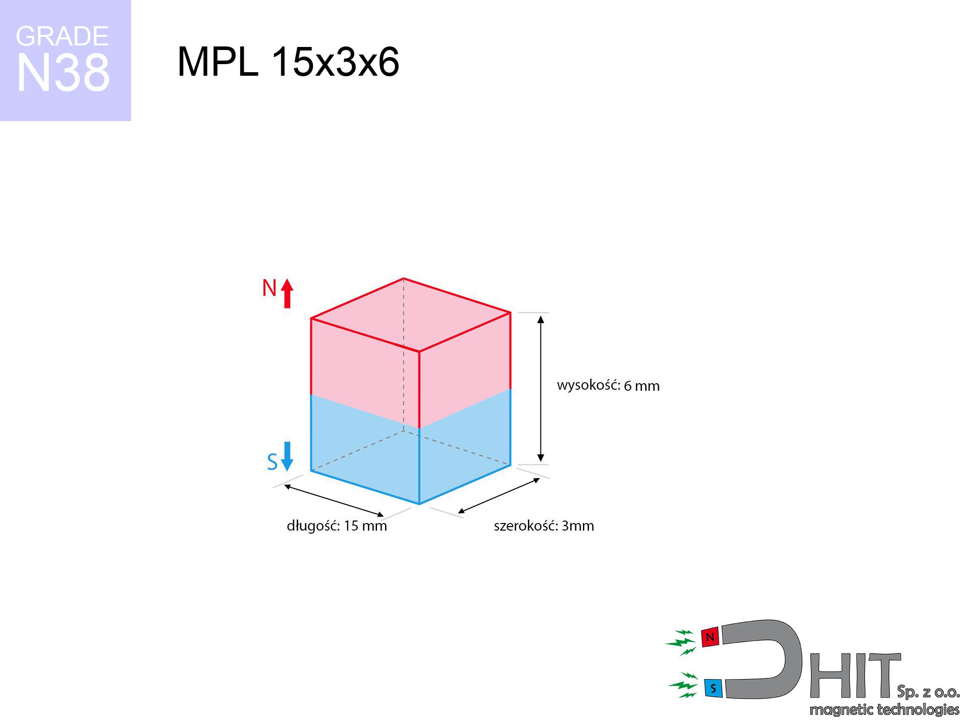
MPL 15x3x6 / N38 - lamellar magnet
lamellar magnet
Catalog no 020122
GTIN/EAN: 5906301811282
length
15 mm [±0,1 mm]
Width
3 mm [±0,1 mm]
Height
6 mm [±0,1 mm]
Weight
2.03 g
Magnetization Direction
↑ axial
Load capacity
1.90 kg / 18.68 N
Magnetic Induction
543.23 mT / 5432 Gs
Coating
[NiCuNi] Nickel
0.726 ZŁ with VAT / pcs + price for transport
0.590 ZŁ net + 23% VAT / pcs
bulk discounts:
Need more?
Contact us by phone
+48 22 499 98 98
otherwise get in touch by means of
contact form
the contact section.
Parameters and shape of magnetic components can be verified on our
magnetic calculator.
Orders placed before 14:00 will be shipped the same business day.
Detailed specification - MPL 15x3x6 / N38 - lamellar magnet
Specification / characteristics - MPL 15x3x6 / N38 - lamellar magnet
| properties | values |
|---|---|
| Cat. no. | 020122 |
| GTIN/EAN | 5906301811282 |
| Production/Distribution | Dhit sp. z o.o. |
| Country of origin | Poland / China / Germany |
| Customs code | 85059029 |
| length | 15 mm [±0,1 mm] |
| Width | 3 mm [±0,1 mm] |
| Height | 6 mm [±0,1 mm] |
| Weight | 2.03 g |
| Magnetization Direction | ↑ axial |
| Load capacity ~ ? | 1.90 kg / 18.68 N |
| Magnetic Induction ~ ? | 543.23 mT / 5432 Gs |
| Coating | [NiCuNi] Nickel |
| Manufacturing Tolerance | ±0.1 mm |
Magnetic properties of material N38
| properties | values | units |
|---|---|---|
| remenance Br [min. - max.] ? | 12.2-12.6 | kGs |
| remenance Br [min. - max.] ? | 1220-1260 | mT |
| coercivity bHc ? | 10.8-11.5 | kOe |
| coercivity bHc ? | 860-915 | kA/m |
| actual internal force iHc | ≥ 12 | kOe |
| actual internal force iHc | ≥ 955 | kA/m |
| energy density [min. - max.] ? | 36-38 | BH max MGOe |
| energy density [min. - max.] ? | 287-303 | BH max KJ/m |
| max. temperature ? | ≤ 80 | °C |
Physical properties of sintered neodymium magnets Nd2Fe14B at 20°C
| properties | values | units |
|---|---|---|
| Vickers hardness | ≥550 | Hv |
| Density | ≥7.4 | g/cm3 |
| Curie Temperature TC | 312 - 380 | °C |
| Curie Temperature TF | 593 - 716 | °F |
| Specific resistance | 150 | μΩ⋅cm |
| Bending strength | 250 | MPa |
| Compressive strength | 1000~1100 | MPa |
| Thermal expansion parallel (∥) to orientation (M) | (3-4) x 10-6 | °C-1 |
| Thermal expansion perpendicular (⊥) to orientation (M) | -(1-3) x 10-6 | °C-1 |
| Young's modulus | 1.7 x 10⁴ | kg/mm² |
Engineering analysis of the magnet - technical parameters
The following information represent the outcome of a mathematical analysis. Values rely on models for the class Nd2Fe14B. Real-world conditions may differ from theoretical values. Use these data as a supplementary guide during assembly planning.
Table 1: Static pull force (force vs gap) - characteristics
MPL 15x3x6 / N38
| Distance (mm) | Induction (Gauss) / mT | Pull Force (kg/lbs/g/N) | Risk Status |
|---|---|---|---|
| 0 mm |
5423 Gs
542.3 mT
|
1.90 kg / 4.19 lbs
1900.0 g / 18.6 N
|
safe |
| 1 mm |
3221 Gs
322.1 mT
|
0.67 kg / 1.48 lbs
670.2 g / 6.6 N
|
safe |
| 2 mm |
1942 Gs
194.2 mT
|
0.24 kg / 0.54 lbs
243.7 g / 2.4 N
|
safe |
| 3 mm |
1274 Gs
127.4 mT
|
0.10 kg / 0.23 lbs
104.9 g / 1.0 N
|
safe |
| 5 mm |
652 Gs
65.2 mT
|
0.03 kg / 0.06 lbs
27.5 g / 0.3 N
|
safe |
| 10 mm |
195 Gs
19.5 mT
|
0.00 kg / 0.01 lbs
2.5 g / 0.0 N
|
safe |
| 15 mm |
81 Gs
8.1 mT
|
0.00 kg / 0.00 lbs
0.4 g / 0.0 N
|
safe |
| 20 mm |
41 Gs
4.1 mT
|
0.00 kg / 0.00 lbs
0.1 g / 0.0 N
|
safe |
| 30 mm |
14 Gs
1.4 mT
|
0.00 kg / 0.00 lbs
0.0 g / 0.0 N
|
safe |
| 50 mm |
4 Gs
0.4 mT
|
0.00 kg / 0.00 lbs
0.0 g / 0.0 N
|
safe |
Table 2: Shear hold (wall)
MPL 15x3x6 / N38
| Distance (mm) | Friction coefficient | Pull Force (kg/lbs/g/N) |
|---|---|---|
| 0 mm | Stal (~0.2) |
0.38 kg / 0.84 lbs
380.0 g / 3.7 N
|
| 1 mm | Stal (~0.2) |
0.13 kg / 0.30 lbs
134.0 g / 1.3 N
|
| 2 mm | Stal (~0.2) |
0.05 kg / 0.11 lbs
48.0 g / 0.5 N
|
| 3 mm | Stal (~0.2) |
0.02 kg / 0.04 lbs
20.0 g / 0.2 N
|
| 5 mm | Stal (~0.2) |
0.01 kg / 0.01 lbs
6.0 g / 0.1 N
|
| 10 mm | Stal (~0.2) |
0.00 kg / 0.00 lbs
0.0 g / 0.0 N
|
| 15 mm | Stal (~0.2) |
0.00 kg / 0.00 lbs
0.0 g / 0.0 N
|
| 20 mm | Stal (~0.2) |
0.00 kg / 0.00 lbs
0.0 g / 0.0 N
|
| 30 mm | Stal (~0.2) |
0.00 kg / 0.00 lbs
0.0 g / 0.0 N
|
| 50 mm | Stal (~0.2) |
0.00 kg / 0.00 lbs
0.0 g / 0.0 N
|
Table 3: Wall mounting (shearing) - behavior on slippery surfaces
MPL 15x3x6 / N38
| Surface type | Friction coefficient / % Mocy | Max load (kg/lbs/g/N) |
|---|---|---|
| Raw steel |
µ = 0.3
30% Nominalnej Siły
|
0.57 kg / 1.26 lbs
570.0 g / 5.6 N
|
| Painted steel (standard) |
µ = 0.2
20% Nominalnej Siły
|
0.38 kg / 0.84 lbs
380.0 g / 3.7 N
|
| Oily/slippery steel |
µ = 0.1
10% Nominalnej Siły
|
0.19 kg / 0.42 lbs
190.0 g / 1.9 N
|
| Magnet with anti-slip rubber |
µ = 0.5
50% Nominalnej Siły
|
0.95 kg / 2.09 lbs
950.0 g / 9.3 N
|
Table 4: Material efficiency (saturation) - sheet metal selection
MPL 15x3x6 / N38
| Steel thickness (mm) | % power | Real pull force (kg/lbs/g/N) |
|---|---|---|
| 0.5 mm |
|
0.19 kg / 0.42 lbs
190.0 g / 1.9 N
|
| 1 mm |
|
0.48 kg / 1.05 lbs
475.0 g / 4.7 N
|
| 2 mm |
|
0.95 kg / 2.09 lbs
950.0 g / 9.3 N
|
| 3 mm |
|
1.42 kg / 3.14 lbs
1425.0 g / 14.0 N
|
| 5 mm |
|
1.90 kg / 4.19 lbs
1900.0 g / 18.6 N
|
| 10 mm |
|
1.90 kg / 4.19 lbs
1900.0 g / 18.6 N
|
| 11 mm |
|
1.90 kg / 4.19 lbs
1900.0 g / 18.6 N
|
| 12 mm |
|
1.90 kg / 4.19 lbs
1900.0 g / 18.6 N
|
Table 5: Working in heat (material behavior) - power drop
MPL 15x3x6 / N38
| Ambient temp. (°C) | Power loss | Remaining pull (kg/lbs/g/N) | Status |
|---|---|---|---|
| 20 °C | 0.0% |
1.90 kg / 4.19 lbs
1900.0 g / 18.6 N
|
OK |
| 40 °C | -2.2% |
1.86 kg / 4.10 lbs
1858.2 g / 18.2 N
|
OK |
| 60 °C | -4.4% |
1.82 kg / 4.00 lbs
1816.4 g / 17.8 N
|
OK |
| 80 °C | -6.6% |
1.77 kg / 3.91 lbs
1774.6 g / 17.4 N
|
|
| 100 °C | -28.8% |
1.35 kg / 2.98 lbs
1352.8 g / 13.3 N
|
Table 6: Magnet-Magnet interaction (attraction) - field collision
MPL 15x3x6 / N38
| Gap (mm) | Attraction (kg/lbs) (N-S) | Shear Force (kg/lbs/g/N) | Repulsion (kg/lbs) (N-N) |
|---|---|---|---|
| 0 mm |
8.16 kg / 17.99 lbs
5 914 Gs
|
1.22 kg / 2.70 lbs
1224 g / 12.0 N
|
N/A |
| 1 mm |
4.96 kg / 10.94 lbs
8 460 Gs
|
0.74 kg / 1.64 lbs
745 g / 7.3 N
|
4.47 kg / 9.85 lbs
~0 Gs
|
| 2 mm |
2.88 kg / 6.34 lbs
6 441 Gs
|
0.43 kg / 0.95 lbs
432 g / 4.2 N
|
2.59 kg / 5.71 lbs
~0 Gs
|
| 3 mm |
1.70 kg / 3.75 lbs
4 950 Gs
|
0.25 kg / 0.56 lbs
255 g / 2.5 N
|
1.53 kg / 3.37 lbs
~0 Gs
|
| 5 mm |
0.67 kg / 1.48 lbs
3 116 Gs
|
0.10 kg / 0.22 lbs
101 g / 1.0 N
|
0.61 kg / 1.34 lbs
~0 Gs
|
| 10 mm |
0.12 kg / 0.26 lbs
1 304 Gs
|
0.02 kg / 0.04 lbs
18 g / 0.2 N
|
0.11 kg / 0.23 lbs
~0 Gs
|
| 20 mm |
0.01 kg / 0.02 lbs
391 Gs
|
0.00 kg / 0.00 lbs
2 g / 0.0 N
|
0.01 kg / 0.02 lbs
~0 Gs
|
| 50 mm |
0.00 kg / 0.00 lbs
46 Gs
|
0.00 kg / 0.00 lbs
0 g / 0.0 N
|
0.00 kg / 0.00 lbs
~0 Gs
|
| 60 mm |
0.00 kg / 0.00 lbs
29 Gs
|
0.00 kg / 0.00 lbs
0 g / 0.0 N
|
0.00 kg / 0.00 lbs
~0 Gs
|
| 70 mm |
0.00 kg / 0.00 lbs
19 Gs
|
0.00 kg / 0.00 lbs
0 g / 0.0 N
|
0.00 kg / 0.00 lbs
~0 Gs
|
| 80 mm |
0.00 kg / 0.00 lbs
13 Gs
|
0.00 kg / 0.00 lbs
0 g / 0.0 N
|
0.00 kg / 0.00 lbs
~0 Gs
|
| 90 mm |
0.00 kg / 0.00 lbs
9 Gs
|
0.00 kg / 0.00 lbs
0 g / 0.0 N
|
0.00 kg / 0.00 lbs
~0 Gs
|
| 100 mm |
0.00 kg / 0.00 lbs
7 Gs
|
0.00 kg / 0.00 lbs
0 g / 0.0 N
|
0.00 kg / 0.00 lbs
~0 Gs
|
Table 7: Safety (HSE) (implants) - warnings
MPL 15x3x6 / N38
| Object / Device | Limit (Gauss) / mT | Safe distance |
|---|---|---|
| Pacemaker | 5 Gs (0.5 mT) | 4.5 cm |
| Hearing aid | 10 Gs (1.0 mT) | 3.5 cm |
| Mechanical watch | 20 Gs (2.0 mT) | 3.0 cm |
| Mobile device | 40 Gs (4.0 mT) | 2.5 cm |
| Remote | 50 Gs (5.0 mT) | 2.0 cm |
| Payment card | 400 Gs (40.0 mT) | 1.0 cm |
| HDD hard drive | 600 Gs (60.0 mT) | 1.0 cm |
Table 8: Impact energy (cracking risk) - collision effects
MPL 15x3x6 / N38
| Start from (mm) | Speed (km/h) | Energy (J) | Predicted outcome |
|---|---|---|---|
| 10 mm |
30.88 km/h
(8.58 m/s)
|
0.07 J | |
| 30 mm |
53.44 km/h
(14.84 m/s)
|
0.22 J | |
| 50 mm |
68.99 km/h
(19.16 m/s)
|
0.37 J | |
| 100 mm |
97.57 km/h
(27.10 m/s)
|
0.75 J |
Table 9: Anti-corrosion coating durability
MPL 15x3x6 / N38
| Technical parameter | Value / Description |
|---|---|
| Coating type | [NiCuNi] Nickel |
| Layer structure | Nickel - Copper - Nickel |
| Layer thickness | 10-20 µm |
| Salt spray test (SST) ? | 24 h |
| Recommended environment | Indoors only (dry) |
Table 10: Electrical data (Flux)
MPL 15x3x6 / N38
| Parameter | Value | SI Unit / Description |
|---|---|---|
| Magnetic Flux | 2 390 Mx | 23.9 µWb |
| Pc Coefficient | 0.79 | High (Stable) |
Table 11: Hydrostatics and buoyancy
MPL 15x3x6 / N38
| Environment | Effective steel pull | Effect |
|---|---|---|
| Air (land) | 1.90 kg | Standard |
| Water (riverbed) |
2.18 kg
(+0.28 kg buoyancy gain)
|
+14.5% |
1. Wall mount (shear)
*Warning: On a vertical wall, the magnet holds only approx. 20-30% of its max power.
2. Steel saturation
*Thin metal sheet (e.g. computer case) significantly limits the holding force.
3. Power loss vs temp
*For standard magnets, the critical limit is 80°C.
4. Demagnetization curve and operating point (B-H)
chart generated for the permeance coefficient Pc (Permeance Coefficient) = 0.79
The chart above illustrates the magnetic characteristics of the material within the second quadrant of the hysteresis loop. The solid red line represents the demagnetization curve (material potential), while the dashed blue line is the load line based on the magnet's geometry. The Pc (Permeance Coefficient), also known as the load line slope, is a dimensionless value that describes the relationship between the magnet's shape and its magnetic stability. The intersection of these two lines (the black dot) is the operating point — it determines the actual magnetic flux density generated by the magnet in this specific configuration. A higher Pc value means the magnet is more 'slender' (tall relative to its area), resulting in a higher operating point and better resistance to irreversible demagnetization caused by external fields or temperature. A value of 0.42 is relatively low (typical for flat magnets), meaning the operating point is closer to the 'knee' of the curve — caution is advised when operating at temperatures near the maximum limit to avoid strength loss.
Chemical composition
| iron (Fe) | 64% – 68% |
| neodymium (Nd) | 29% – 32% |
| boron (B) | 1.1% – 1.2% |
| dysprosium (Dy) | 0.5% – 2.0% |
| coating (Ni-Cu-Ni) | < 0.05% |
Environmental data
| recyclability (EoL) | 100% |
| recycled raw materials | ~10% (pre-cons) |
| carbon footprint | low / zredukowany |
| waste code (EWC) | 16 02 16 |
Other deals
![UI 45x13x6 [C321] / N38 - badge holder](https://cdn3.dhit.pl/graphics/products/ui45x13x6-c321-jic.jpg "UI 45x13x6 [C321] / N38 - badge holder")
![UMP 107x40 [M8+M10] GW F400 Lina / N38 - search holder](https://cdn3.dhit.pl/graphics/products/ump-107x40-m8+m10-gw-f400-+lina-bel.jpg "UMP 107x40 [M8+M10] GW F400 Lina / N38 - search holder")
![SM 32x450 [2xM8] / N52 - magnetic separator](https://cdn3.dhit.pl/graphics/products/sm-32x450-2xm8-bir.jpg "SM 32x450 [2xM8] / N52 - magnetic separator")

Pros as well as cons of neodymium magnets.
Pros
- They retain attractive force for around 10 years – the drop is just ~1% (based on simulations),
- They are resistant to demagnetization induced by external disturbances,
- The use of an metallic layer of noble metals (nickel, gold, silver) causes the element to look better,
- The surface of neodymium magnets generates a intense magnetic field – this is a key feature,
- Through (appropriate) combination of ingredients, they can achieve high thermal resistance, enabling action at temperatures approaching 230°C and above...
- Possibility of custom modeling as well as modifying to specific needs,
- Huge importance in high-tech industry – they serve a role in computer drives, drive modules, diagnostic systems, and complex engineering applications.
- Thanks to their power density, small magnets offer high operating force, in miniature format,
Weaknesses
- They are fragile upon heavy impacts. To avoid cracks, it is worth securing magnets using a steel holder. Such protection not only shields the magnet but also improves its resistance to damage
- When exposed to high temperature, neodymium magnets suffer a drop in strength. Often, when the temperature exceeds 80°C, their power decreases (depending on the size, as well as shape of the magnet). For those who need magnets for extreme conditions, we offer [AH] versions withstanding up to 230°C
- They rust in a humid environment - during use outdoors we suggest using waterproof magnets e.g. in rubber, plastic
- Due to limitations in producing nuts and complicated shapes in magnets, we recommend using cover - magnetic mechanism.
- Potential hazard related to microscopic parts of magnets can be dangerous, if swallowed, which is particularly important in the context of child safety. Additionally, tiny parts of these magnets can be problematic in diagnostics medical in case of swallowing.
- Higher cost of purchase is one of the disadvantages compared to ceramic magnets, especially in budget applications
Lifting parameters
Maximum holding power of the magnet – what contributes to it?
- using a base made of low-carbon steel, functioning as a circuit closing element
- with a cross-section of at least 10 mm
- characterized by smoothness
- without any clearance between the magnet and steel
- for force acting at a right angle (pull-off, not shear)
- in stable room temperature
Impact of factors on magnetic holding capacity in practice
- Clearance – existence of foreign body (rust, tape, gap) acts as an insulator, which lowers capacity rapidly (even by 50% at 0.5 mm).
- Angle of force application – maximum parameter is reached only during pulling at a 90° angle. The resistance to sliding of the magnet along the surface is standardly several times smaller (approx. 1/5 of the lifting capacity).
- Wall thickness – thin material does not allow full use of the magnet. Magnetic flux penetrates through instead of converting into lifting capacity.
- Chemical composition of the base – mild steel attracts best. Alloy steels reduce magnetic permeability and holding force.
- Plate texture – ground elements guarantee perfect abutment, which improves force. Rough surfaces reduce efficiency.
- Thermal environment – heating the magnet results in weakening of force. It is worth remembering the thermal limit for a given model.
Holding force was checked on a smooth steel plate of 20 mm thickness, when the force acted perpendicularly, in contrast under parallel forces the load capacity is reduced by as much as fivefold. In addition, even a minimal clearance between the magnet and the plate decreases the lifting capacity.
H&S for magnets
Immense force
Before starting, check safety instructions. Uncontrolled attraction can destroy the magnet or hurt your hand. Be predictive.
Fire warning
Combustion risk: Rare earth powder is highly flammable. Do not process magnets without safety gear as this risks ignition.
Sensitization to coating
Certain individuals experience a hypersensitivity to Ni, which is the typical protective layer for NdFeB magnets. Frequent touching may cause skin redness. We recommend use safety gloves.
Health Danger
People with a heart stimulator must maintain an absolute distance from magnets. The magnetism can disrupt the operation of the life-saving device.
Data carriers
Data protection: Neodymium magnets can ruin data carriers and sensitive devices (heart implants, medical aids, mechanical watches).
Magnets are brittle
Protect your eyes. Magnets can fracture upon violent connection, launching shards into the air. We recommend safety glasses.
Product not for children
Always store magnets away from children. Choking hazard is high, and the consequences of magnets clamping inside the body are tragic.
GPS Danger
Navigation devices and mobile phones are highly sensitive to magnetism. Close proximity with a strong magnet can decalibrate the internal compass in your phone.
Hand protection
Large magnets can crush fingers in a fraction of a second. Under no circumstances put your hand between two attracting surfaces.
Operating temperature
Monitor thermal conditions. Exposing the magnet above 80 degrees Celsius will destroy its properties and strength.
Tabela kosztu i czasu dostawy
Płatność przed wysyłką:

GLS kurier
Przesyłka będzie u Ciebie za 2-3 dni
14.99 ZŁ

InPost Paczkomaty 24/7
Przesyłka będzie u Ciebie za 1-2 dni
12.30 ZŁ
Płatność przy odbiorze (pobranie):
GLS kurier
Przesyłka będzie u Ciebie za 1-2 dni
23.00 ZŁ
Rate the product
Your rating