
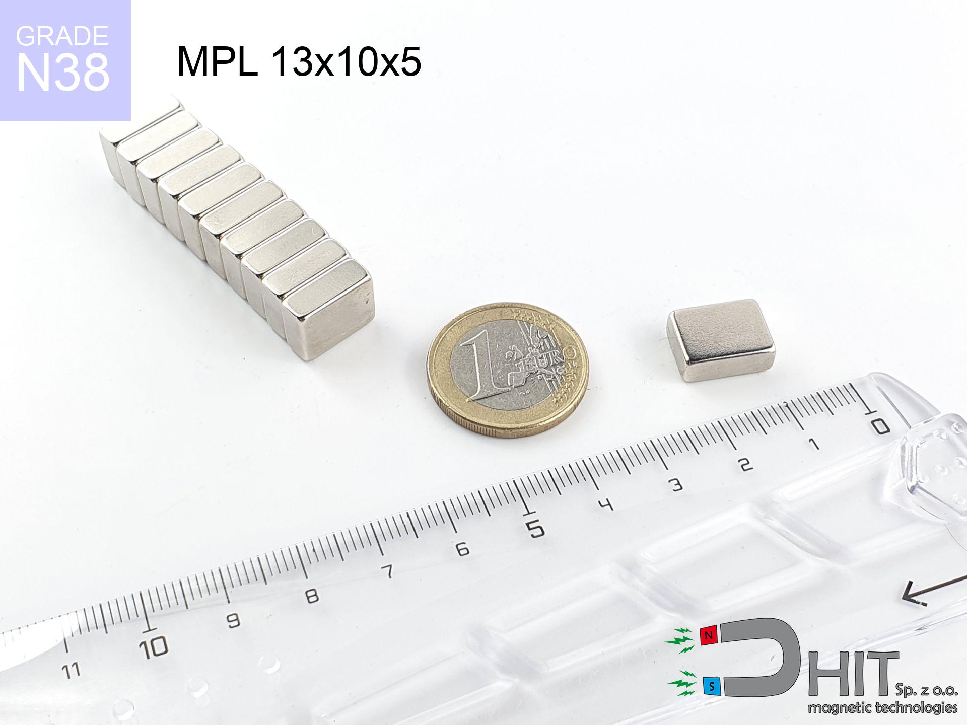
MPL 13x10x5 / N35H - lamellar magnet
lamellar magnet
Catalog no 020119
GTIN/EAN: 5906301811251
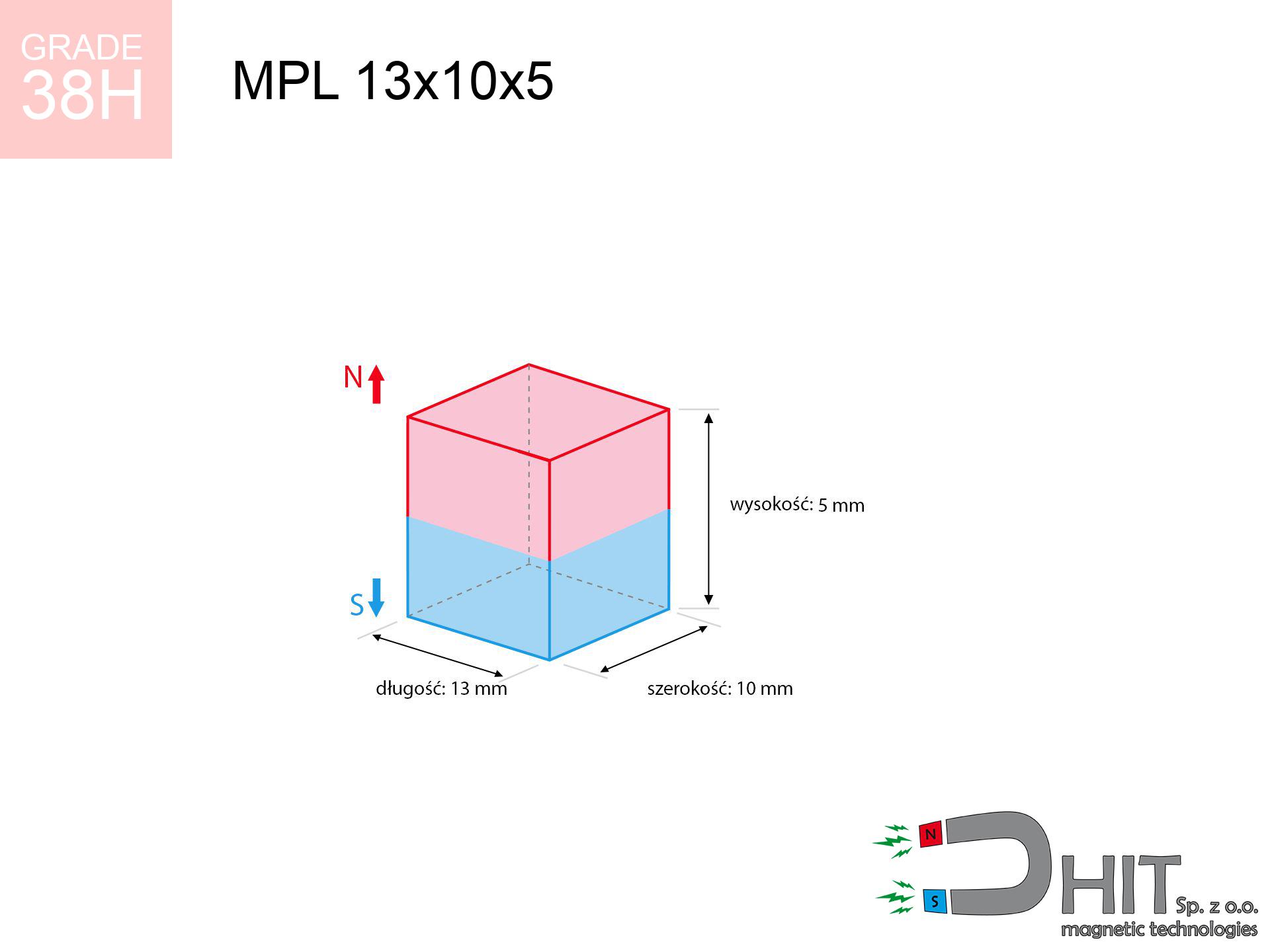
length
13 mm [±0,1 mm]
Width
10 mm [±0,1 mm]
Height
5 mm [±0,1 mm]
Weight
4.88 g
Magnetization Direction
↑ axial
Load capacity
4.03 kg / 39.54 N
Magnetic Induction
369.32 mT / 3693 Gs
Coating
[NiCuNi] Nickel
2.58 ZŁ with VAT / pcs + price for transport
2.10 ZŁ net + 23% VAT / pcs
bulk discounts:
Need more?
Call us
+48 888 99 98 98
alternatively contact us through
inquiry form
the contact section.
Specifications as well as shape of magnetic components can be checked using our
magnetic mass calculator.
Orders submitted before 14:00 will be dispatched today!
Product card - MPL 13x10x5 / N35H - lamellar magnet
Specification / characteristics - MPL 13x10x5 / N35H - lamellar magnet
| properties | values |
|---|---|
| Cat. no. | 020119 |
| GTIN/EAN | 5906301811251 |
| Production/Distribution | Dhit sp. z o.o. |
| Country of origin | Poland / China / Germany |
| Customs code | 85059029 |
| length | 13 mm [±0,1 mm] |
| Width | 10 mm [±0,1 mm] |
| Height | 5 mm [±0,1 mm] |
| Weight | 4.88 g |
| Magnetization Direction | ↑ axial |
| Load capacity ~ ? | 4.03 kg / 39.54 N |
| Magnetic Induction ~ ? | 369.32 mT / 3693 Gs |
| Coating | [NiCuNi] Nickel |
| Manufacturing Tolerance | ±0.1 mm |
Magnetic properties of material N35H
| properties | values | units |
|---|---|---|
| remenance Br [min. - max.] ? | 11.7-12.1 | kGs |
| remenance Br [min. - max.] ? | 1170-1210 | mT |
| coercivity bHc ? | 10.8-11.5 | kOe |
| coercivity bHc ? | 860-915 | kA/m |
| actual internal force iHc | ≥ 17 | kOe |
| actual internal force iHc | ≥ 1353 | kA/m |
| energy density [min. - max.] ? | 33-35 | BH max MGOe |
| energy density [min. - max.] ? | 263-279 | BH max KJ/m |
| max. temperature ? | ≤ 120 | °C |
Physical properties of sintered neodymium magnets Nd2Fe14B at 20°C
| properties | values | units |
|---|---|---|
| Vickers hardness | ≥550 | Hv |
| Density | ≥7.4 | g/cm3 |
| Curie Temperature TC | 312 - 380 | °C |
| Curie Temperature TF | 593 - 716 | °F |
| Specific resistance | 150 | μΩ⋅cm |
| Bending strength | 250 | MPa |
| Compressive strength | 1000~1100 | MPa |
| Thermal expansion parallel (∥) to orientation (M) | (3-4) x 10-6 | °C-1 |
| Thermal expansion perpendicular (⊥) to orientation (M) | -(1-3) x 10-6 | °C-1 |
| Young's modulus | 1.7 x 10⁴ | kg/mm² |
Technical simulation of the product - data
The following information are the result of a physical simulation. Results were calculated on models for the material Nd2Fe14B. Actual parameters might slightly deviate from the simulation results. Use these data as a supplementary guide for designers.
Table 1: Static pull force (pull vs distance) - characteristics
MPL 13x10x5 / N35H
| Distance (mm) | Induction (Gauss) / mT | Pull Force (kg/lbs/g/N) | Risk Status |
|---|---|---|---|
| 0 mm |
3691 Gs
369.1 mT
|
4.03 kg / 8.88 pounds
4030.0 g / 39.5 N
|
strong |
| 1 mm |
3152 Gs
315.2 mT
|
2.94 kg / 6.48 pounds
2938.4 g / 28.8 N
|
strong |
| 2 mm |
2595 Gs
259.5 mT
|
1.99 kg / 4.39 pounds
1991.8 g / 19.5 N
|
safe |
| 3 mm |
2089 Gs
208.9 mT
|
1.29 kg / 2.85 pounds
1291.2 g / 12.7 N
|
safe |
| 5 mm |
1321 Gs
132.1 mT
|
0.52 kg / 1.14 pounds
516.1 g / 5.1 N
|
safe |
| 10 mm |
455 Gs
45.5 mT
|
0.06 kg / 0.14 pounds
61.2 g / 0.6 N
|
safe |
| 15 mm |
193 Gs
19.3 mT
|
0.01 kg / 0.02 pounds
11.1 g / 0.1 N
|
safe |
| 20 mm |
97 Gs
9.7 mT
|
0.00 kg / 0.01 pounds
2.8 g / 0.0 N
|
safe |
| 30 mm |
34 Gs
3.4 mT
|
0.00 kg / 0.00 pounds
0.3 g / 0.0 N
|
safe |
| 50 mm |
8 Gs
0.8 mT
|
0.00 kg / 0.00 pounds
0.0 g / 0.0 N
|
safe |
Table 2: Shear load (vertical surface)
MPL 13x10x5 / N35H
| Distance (mm) | Friction coefficient | Pull Force (kg/lbs/g/N) |
|---|---|---|
| 0 mm | Stal (~0.2) |
0.81 kg / 1.78 pounds
806.0 g / 7.9 N
|
| 1 mm | Stal (~0.2) |
0.59 kg / 1.30 pounds
588.0 g / 5.8 N
|
| 2 mm | Stal (~0.2) |
0.40 kg / 0.88 pounds
398.0 g / 3.9 N
|
| 3 mm | Stal (~0.2) |
0.26 kg / 0.57 pounds
258.0 g / 2.5 N
|
| 5 mm | Stal (~0.2) |
0.10 kg / 0.23 pounds
104.0 g / 1.0 N
|
| 10 mm | Stal (~0.2) |
0.01 kg / 0.03 pounds
12.0 g / 0.1 N
|
| 15 mm | Stal (~0.2) |
0.00 kg / 0.00 pounds
2.0 g / 0.0 N
|
| 20 mm | Stal (~0.2) |
0.00 kg / 0.00 pounds
0.0 g / 0.0 N
|
| 30 mm | Stal (~0.2) |
0.00 kg / 0.00 pounds
0.0 g / 0.0 N
|
| 50 mm | Stal (~0.2) |
0.00 kg / 0.00 pounds
0.0 g / 0.0 N
|
Table 3: Wall mounting (shearing) - vertical pull
MPL 13x10x5 / N35H
| Surface type | Friction coefficient / % Mocy | Max load (kg/lbs/g/N) |
|---|---|---|
| Raw steel |
µ = 0.3
30% Nominalnej Siły
|
1.21 kg / 2.67 pounds
1209.0 g / 11.9 N
|
| Painted steel (standard) |
µ = 0.2
20% Nominalnej Siły
|
0.81 kg / 1.78 pounds
806.0 g / 7.9 N
|
| Oily/slippery steel |
µ = 0.1
10% Nominalnej Siły
|
0.40 kg / 0.89 pounds
403.0 g / 4.0 N
|
| Magnet with anti-slip rubber |
µ = 0.5
50% Nominalnej Siły
|
2.02 kg / 4.44 pounds
2015.0 g / 19.8 N
|
Table 4: Steel thickness (saturation) - power losses
MPL 13x10x5 / N35H
| Steel thickness (mm) | % power | Real pull force (kg/lbs/g/N) |
|---|---|---|
| 0.5 mm |
|
0.40 kg / 0.89 pounds
403.0 g / 4.0 N
|
| 1 mm |
|
1.01 kg / 2.22 pounds
1007.5 g / 9.9 N
|
| 2 mm |
|
2.02 kg / 4.44 pounds
2015.0 g / 19.8 N
|
| 3 mm |
|
3.02 kg / 6.66 pounds
3022.5 g / 29.7 N
|
| 5 mm |
|
4.03 kg / 8.88 pounds
4030.0 g / 39.5 N
|
| 10 mm |
|
4.03 kg / 8.88 pounds
4030.0 g / 39.5 N
|
| 11 mm |
|
4.03 kg / 8.88 pounds
4030.0 g / 39.5 N
|
| 12 mm |
|
4.03 kg / 8.88 pounds
4030.0 g / 39.5 N
|
Table 5: Working in heat (material behavior) - thermal limit
MPL 13x10x5 / N35H
| Ambient temp. (°C) | Power loss | Remaining pull (kg/lbs/g/N) | Status |
|---|---|---|---|
| 20 °C | 0.0% |
4.03 kg / 8.88 pounds
4030.0 g / 39.5 N
|
OK |
| 80 °C | -6.6% |
3.76 kg / 8.30 pounds
3764.0 g / 36.9 N
|
|
| 120 °C | -11.0% |
3.59 kg / 7.91 pounds
3586.7 g / 35.2 N
|
|
| 140 °C | -33.2% |
2.69 kg / 5.93 pounds
2692.0 g / 26.4 N
|
Table 6: Two magnets (repulsion) - field collision
MPL 13x10x5 / N35H
| Gap (mm) | Attraction (kg/lbs) (N-S) | Shear Force (kg/lbs/g/N) | Repulsion (kg/lbs) (N-N) |
|---|---|---|---|
| 0 mm |
10.92 kg / 24.08 pounds
5 009 Gs
|
1.64 kg / 3.61 pounds
1638 g / 16.1 N
|
N/A |
| 1 mm |
9.43 kg / 20.80 pounds
6 862 Gs
|
1.42 kg / 3.12 pounds
1415 g / 13.9 N
|
8.49 kg / 18.72 pounds
~0 Gs
|
| 2 mm |
7.96 kg / 17.55 pounds
6 304 Gs
|
1.19 kg / 2.63 pounds
1194 g / 11.7 N
|
7.17 kg / 15.80 pounds
~0 Gs
|
| 3 mm |
6.60 kg / 14.56 pounds
5 740 Gs
|
0.99 kg / 2.18 pounds
990 g / 9.7 N
|
5.94 kg / 13.10 pounds
~0 Gs
|
| 5 mm |
4.36 kg / 9.62 pounds
4 667 Gs
|
0.65 kg / 1.44 pounds
655 g / 6.4 N
|
3.93 kg / 8.66 pounds
~0 Gs
|
| 10 mm |
1.40 kg / 3.08 pounds
2 642 Gs
|
0.21 kg / 0.46 pounds
210 g / 2.1 N
|
1.26 kg / 2.78 pounds
~0 Gs
|
| 20 mm |
0.17 kg / 0.37 pounds
910 Gs
|
0.02 kg / 0.05 pounds
25 g / 0.2 N
|
0.15 kg / 0.33 pounds
~0 Gs
|
| 50 mm |
0.00 kg / 0.01 pounds
110 Gs
|
0.00 kg / 0.00 pounds
0 g / 0.0 N
|
0.00 kg / 0.00 pounds
~0 Gs
|
| 60 mm |
0.00 kg / 0.00 pounds
68 Gs
|
0.00 kg / 0.00 pounds
0 g / 0.0 N
|
0.00 kg / 0.00 pounds
~0 Gs
|
| 70 mm |
0.00 kg / 0.00 pounds
45 Gs
|
0.00 kg / 0.00 pounds
0 g / 0.0 N
|
0.00 kg / 0.00 pounds
~0 Gs
|
| 80 mm |
0.00 kg / 0.00 pounds
31 Gs
|
0.00 kg / 0.00 pounds
0 g / 0.0 N
|
0.00 kg / 0.00 pounds
~0 Gs
|
| 90 mm |
0.00 kg / 0.00 pounds
22 Gs
|
0.00 kg / 0.00 pounds
0 g / 0.0 N
|
0.00 kg / 0.00 pounds
~0 Gs
|
| 100 mm |
0.00 kg / 0.00 pounds
17 Gs
|
0.00 kg / 0.00 pounds
0 g / 0.0 N
|
0.00 kg / 0.00 pounds
~0 Gs
|
Table 7: Protective zones (electronics) - precautionary measures
MPL 13x10x5 / N35H
| Object / Device | Limit (Gauss) / mT | Safe distance |
|---|---|---|
| Pacemaker | 5 Gs (0.5 mT) | 6.0 cm |
| Hearing aid | 10 Gs (1.0 mT) | 5.0 cm |
| Mechanical watch | 20 Gs (2.0 mT) | 4.0 cm |
| Phone / Smartphone | 40 Gs (4.0 mT) | 3.0 cm |
| Remote | 50 Gs (5.0 mT) | 3.0 cm |
| Payment card | 400 Gs (40.0 mT) | 1.5 cm |
| HDD hard drive | 600 Gs (60.0 mT) | 1.0 cm |
Table 8: Collisions (kinetic energy) - warning
MPL 13x10x5 / N35H
| Start from (mm) | Speed (km/h) | Energy (J) | Predicted outcome |
|---|---|---|---|
| 10 mm |
29.26 km/h
(8.13 m/s)
|
0.16 J | |
| 30 mm |
50.20 km/h
(13.94 m/s)
|
0.47 J | |
| 50 mm |
64.81 km/h
(18.00 m/s)
|
0.79 J | |
| 100 mm |
91.65 km/h
(25.46 m/s)
|
1.58 J |
Table 9: Anti-corrosion coating durability
MPL 13x10x5 / N35H
| Technical parameter | Value / Description |
|---|---|
| Coating type | [NiCuNi] Nickel |
| Layer structure | Nickel - Copper - Nickel |
| Layer thickness | 10-20 µm |
| Salt spray test (SST) ? | 24 h |
| Recommended environment | Indoors only (dry) |
Table 10: Electrical data (Flux)
MPL 13x10x5 / N35H
| Parameter | Value | SI Unit / Description |
|---|---|---|
| Magnetic Flux | 4 919 Mx | 49.2 µWb |
| Pc Coefficient | 0.49 | Low (Flat) |
Table 11: Physics of underwater searching
MPL 13x10x5 / N35H
| Environment | Effective steel pull | Effect |
|---|---|---|
| Air (land) | 4.03 kg | Standard |
| Water (riverbed) |
4.61 kg
(+0.58 kg buoyancy gain)
|
+14.5% |
1. Wall mount (shear)
*Caution: On a vertical wall, the magnet retains merely a fraction of its perpendicular strength.
2. Plate thickness effect
*Thin steel (e.g. 0.5mm PC case) significantly reduces the holding force.
3. Thermal stability
*For standard magnets, the max working temp is 80°C.
4. Demagnetization curve and operating point (B-H)
chart generated for the permeance coefficient Pc (Permeance Coefficient) = 0.49
The chart above illustrates the magnetic characteristics of the material within the second quadrant of the hysteresis loop. The solid red line represents the demagnetization curve (material potential), while the dashed blue line is the load line based on the magnet's geometry. The Pc (Permeance Coefficient), also known as the load line slope, is a dimensionless value that describes the relationship between the magnet's shape and its magnetic stability. The intersection of these two lines (the black dot) is the operating point — it determines the actual magnetic flux density generated by the magnet in this specific configuration. A higher Pc value means the magnet is more 'slender' (tall relative to its area), resulting in a higher operating point and better resistance to irreversible demagnetization caused by external fields or temperature. A value of 0.42 is relatively low (typical for flat magnets), meaning the operating point is closer to the 'knee' of the curve — caution is advised when operating at temperatures near the maximum limit to avoid strength loss.
Material specification
| iron (Fe) | 64% – 68% |
| neodymium (Nd) | 29% – 32% |
| boron (B) | 1.1% – 1.2% |
| dysprosium (Dy) | 0.5% – 2.0% |
| coating (Ni-Cu-Ni) | < 0.05% |
Sustainability
| recyclability (EoL) | 100% |
| recycled raw materials | ~10% (pre-cons) |
| carbon footprint | low / zredukowany |
| waste code (EWC) | 16 02 16 |
Other offers

![UMGW 42x20x9 [M6] GW / N38 - magnetic holder internal thread](https://cdn3.dhit.pl/graphics/products/um-42x20x9-m8-gw-god.jpg "UMGW 42x20x9 [M6] GW / N38 - magnetic holder internal thread")


Strengths as well as weaknesses of rare earth magnets.
Benefits
- They do not lose magnetism, even during around ten years – the drop in strength is only ~1% (theoretically),
- They are resistant to demagnetization induced by external field influence,
- A magnet with a metallic nickel surface looks better,
- Neodymium magnets achieve maximum magnetic induction on a small surface, which ensures high operational effectiveness,
- Thanks to resistance to high temperature, they are capable of working (depending on the shape) even at temperatures up to 230°C and higher...
- Thanks to freedom in shaping and the ability to modify to unusual requirements,
- Key role in advanced technology sectors – they find application in computer drives, electric motors, medical equipment, also industrial machines.
- Relatively small size with high pulling force – neodymium magnets offer high power in tiny dimensions, which makes them useful in compact constructions
Cons
- To avoid cracks upon strong impacts, we suggest using special steel housings. Such a solution protects the magnet and simultaneously improves its durability.
- When exposed to high temperature, neodymium magnets suffer a drop in force. Often, when the temperature exceeds 80°C, their power decreases (depending on the size and shape of the magnet). For those who need magnets for extreme conditions, we offer [AH] versions withstanding up to 230°C
- When exposed to humidity, magnets start to rust. To use them in conditions outside, it is recommended to use protective magnets, such as magnets in rubber or plastics, which prevent oxidation as well as corrosion.
- Limited possibility of making nuts in the magnet and complicated shapes - recommended is casing - magnetic holder.
- Potential hazard related to microscopic parts of magnets are risky, when accidentally swallowed, which gains importance in the context of child health protection. Additionally, small elements of these products can be problematic in diagnostics medical in case of swallowing.
- Due to complex production process, their price is higher than average,
Holding force characteristics
Best holding force of the magnet in ideal parameters – what it depends on?
- on a plate made of structural steel, optimally conducting the magnetic flux
- whose thickness is min. 10 mm
- with an polished contact surface
- under conditions of no distance (surface-to-surface)
- under perpendicular force vector (90-degree angle)
- at conditions approx. 20°C
Practical lifting capacity: influencing factors
- Distance (between the magnet and the plate), as even a microscopic clearance (e.g. 0.5 mm) can cause a reduction in force by up to 50% (this also applies to varnish, corrosion or debris).
- Force direction – catalog parameter refers to detachment vertically. When slipping, the magnet holds much less (often approx. 20-30% of maximum force).
- Element thickness – to utilize 100% power, the steel must be adequately massive. Paper-thin metal restricts the lifting capacity (the magnet "punches through" it).
- Steel grade – the best choice is high-permeability steel. Hardened steels may attract less.
- Smoothness – full contact is obtained only on smooth steel. Any scratches and bumps create air cushions, reducing force.
- Thermal environment – heating the magnet results in weakening of induction. It is worth remembering the maximum operating temperature for a given model.
Holding force was tested on the plate surface of 20 mm thickness, when a perpendicular force was applied, in contrast under parallel forces the holding force is lower. Additionally, even a slight gap between the magnet’s surface and the plate reduces the lifting capacity.
Warnings
Finger safety
Big blocks can smash fingers in a fraction of a second. Never place your hand between two attracting surfaces.
Medical implants
For implant holders: Powerful magnets affect electronics. Maintain at least 30 cm distance or ask another person to work with the magnets.
Product not for children
Product intended for adults. Tiny parts pose a choking risk, causing intestinal necrosis. Keep away from children and animals.
Handling guide
Before starting, read the rules. Uncontrolled attraction can destroy the magnet or injure your hand. Think ahead.
Demagnetization risk
Standard neodymium magnets (N-type) undergo demagnetization when the temperature surpasses 80°C. The loss of strength is permanent.
Magnets are brittle
Beware of splinters. Magnets can fracture upon violent connection, launching sharp fragments into the air. We recommend safety glasses.
GPS and phone interference
GPS units and mobile phones are highly susceptible to magnetic fields. Close proximity with a powerful NdFeB magnet can decalibrate the sensors in your phone.
Dust explosion hazard
Machining of NdFeB material poses a fire risk. Neodymium dust reacts violently with oxygen and is hard to extinguish.
Skin irritation risks
Warning for allergy sufferers: The nickel-copper-nickel coating contains nickel. If skin irritation occurs, immediately stop handling magnets and wear gloves.
Electronic devices
Data protection: Strong magnets can damage payment cards and sensitive devices (heart implants, hearing aids, mechanical watches).
Tabela kosztu i czasu dostawy
Płatność przed wysyłką:

GLS kurier
Przesyłka będzie u Ciebie za 2-3 dni
14.99 ZŁ

InPost Paczkomaty 24/7
Przesyłka będzie u Ciebie za 1-2 dni
12.30 ZŁ
Płatność przy odbiorze (pobranie):
GLS kurier
Przesyłka będzie u Ciebie za 1-2 dni
23.00 ZŁ
Rate the product
Your rating