

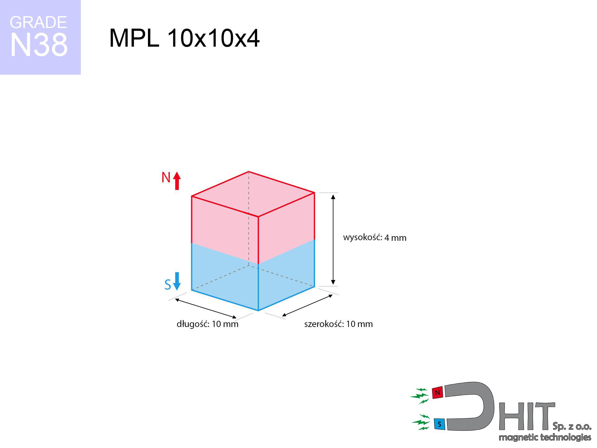
MPL 10x10x4 / N38 - lamellar magnet
lamellar magnet
Catalog no 020112
GTIN/EAN: 5906301811183
length
10 mm [±0,1 mm]
Width
10 mm [±0,1 mm]
Height
4 mm [±0,1 mm]
Weight
3 g
Magnetization Direction
↑ axial
Load capacity
3.10 kg / 30.39 N
Magnetic Induction
360.85 mT / 3608 Gs
Coating
[NiCuNi] Nickel
1.538 ZŁ with VAT / pcs + price for transport
1.250 ZŁ net + 23% VAT / pcs
bulk discounts:
Need more?
Call us
+48 22 499 98 98
otherwise get in touch using
inquiry form
the contact section.
Force and shape of magnetic components can be analyzed on our
force calculator.
Order by 14:00 and we’ll ship today!
Technical - MPL 10x10x4 / N38 - lamellar magnet
Specification / characteristics - MPL 10x10x4 / N38 - lamellar magnet
| properties | values |
|---|---|
| Cat. no. | 020112 |
| GTIN/EAN | 5906301811183 |
| Production/Distribution | Dhit sp. z o.o. |
| Country of origin | Poland / China / Germany |
| Customs code | 85059029 |
| length | 10 mm [±0,1 mm] |
| Width | 10 mm [±0,1 mm] |
| Height | 4 mm [±0,1 mm] |
| Weight | 3 g |
| Magnetization Direction | ↑ axial |
| Load capacity ~ ? | 3.10 kg / 30.39 N |
| Magnetic Induction ~ ? | 360.85 mT / 3608 Gs |
| Coating | [NiCuNi] Nickel |
| Manufacturing Tolerance | ±0.1 mm |
Magnetic properties of material N38
| properties | values | units |
|---|---|---|
| remenance Br [min. - max.] ? | 12.2-12.6 | kGs |
| remenance Br [min. - max.] ? | 1220-1260 | mT |
| coercivity bHc ? | 10.8-11.5 | kOe |
| coercivity bHc ? | 860-915 | kA/m |
| actual internal force iHc | ≥ 12 | kOe |
| actual internal force iHc | ≥ 955 | kA/m |
| energy density [min. - max.] ? | 36-38 | BH max MGOe |
| energy density [min. - max.] ? | 287-303 | BH max KJ/m |
| max. temperature ? | ≤ 80 | °C |
Physical properties of sintered neodymium magnets Nd2Fe14B at 20°C
| properties | values | units |
|---|---|---|
| Vickers hardness | ≥550 | Hv |
| Density | ≥7.4 | g/cm3 |
| Curie Temperature TC | 312 - 380 | °C |
| Curie Temperature TF | 593 - 716 | °F |
| Specific resistance | 150 | μΩ⋅cm |
| Bending strength | 250 | MPa |
| Compressive strength | 1000~1100 | MPa |
| Thermal expansion parallel (∥) to orientation (M) | (3-4) x 10-6 | °C-1 |
| Thermal expansion perpendicular (⊥) to orientation (M) | -(1-3) x 10-6 | °C-1 |
| Young's modulus | 1.7 x 10⁴ | kg/mm² |
Engineering simulation of the product - report
Presented values constitute the result of a mathematical simulation. Values rely on algorithms for the class Nd2Fe14B. Actual performance may deviate from the simulation results. Use these data as a preliminary roadmap for designers.
Table 1: Static force (pull vs distance) - characteristics
MPL 10x10x4 / N38
| Distance (mm) | Induction (Gauss) / mT | Pull Force (kg/lbs/g/N) | Risk Status |
|---|---|---|---|
| 0 mm |
3606 Gs
360.6 mT
|
3.10 kg / 6.83 lbs
3100.0 g / 30.4 N
|
medium risk |
| 1 mm |
3035 Gs
303.5 mT
|
2.20 kg / 4.84 lbs
2195.5 g / 21.5 N
|
medium risk |
| 2 mm |
2436 Gs
243.6 mT
|
1.41 kg / 3.12 lbs
1413.8 g / 13.9 N
|
weak grip |
| 3 mm |
1900 Gs
190.0 mT
|
0.86 kg / 1.90 lbs
860.8 g / 8.4 N
|
weak grip |
| 5 mm |
1127 Gs
112.7 mT
|
0.30 kg / 0.67 lbs
302.7 g / 3.0 N
|
weak grip |
| 10 mm |
347 Gs
34.7 mT
|
0.03 kg / 0.06 lbs
28.8 g / 0.3 N
|
weak grip |
| 15 mm |
140 Gs
14.0 mT
|
0.00 kg / 0.01 lbs
4.6 g / 0.0 N
|
weak grip |
| 20 mm |
68 Gs
6.8 mT
|
0.00 kg / 0.00 lbs
1.1 g / 0.0 N
|
weak grip |
| 30 mm |
23 Gs
2.3 mT
|
0.00 kg / 0.00 lbs
0.1 g / 0.0 N
|
weak grip |
| 50 mm |
6 Gs
0.6 mT
|
0.00 kg / 0.00 lbs
0.0 g / 0.0 N
|
weak grip |
Table 2: Vertical hold (vertical surface)
MPL 10x10x4 / N38
| Distance (mm) | Friction coefficient | Pull Force (kg/lbs/g/N) |
|---|---|---|
| 0 mm | Stal (~0.2) |
0.62 kg / 1.37 lbs
620.0 g / 6.1 N
|
| 1 mm | Stal (~0.2) |
0.44 kg / 0.97 lbs
440.0 g / 4.3 N
|
| 2 mm | Stal (~0.2) |
0.28 kg / 0.62 lbs
282.0 g / 2.8 N
|
| 3 mm | Stal (~0.2) |
0.17 kg / 0.38 lbs
172.0 g / 1.7 N
|
| 5 mm | Stal (~0.2) |
0.06 kg / 0.13 lbs
60.0 g / 0.6 N
|
| 10 mm | Stal (~0.2) |
0.01 kg / 0.01 lbs
6.0 g / 0.1 N
|
| 15 mm | Stal (~0.2) |
0.00 kg / 0.00 lbs
0.0 g / 0.0 N
|
| 20 mm | Stal (~0.2) |
0.00 kg / 0.00 lbs
0.0 g / 0.0 N
|
| 30 mm | Stal (~0.2) |
0.00 kg / 0.00 lbs
0.0 g / 0.0 N
|
| 50 mm | Stal (~0.2) |
0.00 kg / 0.00 lbs
0.0 g / 0.0 N
|
Table 3: Wall mounting (shearing) - vertical pull
MPL 10x10x4 / N38
| Surface type | Friction coefficient / % Mocy | Max load (kg/lbs/g/N) |
|---|---|---|
| Raw steel |
µ = 0.3
30% Nominalnej Siły
|
0.93 kg / 2.05 lbs
930.0 g / 9.1 N
|
| Painted steel (standard) |
µ = 0.2
20% Nominalnej Siły
|
0.62 kg / 1.37 lbs
620.0 g / 6.1 N
|
| Oily/slippery steel |
µ = 0.1
10% Nominalnej Siły
|
0.31 kg / 0.68 lbs
310.0 g / 3.0 N
|
| Magnet with anti-slip rubber |
µ = 0.5
50% Nominalnej Siły
|
1.55 kg / 3.42 lbs
1550.0 g / 15.2 N
|
Table 4: Steel thickness (saturation) - sheet metal selection
MPL 10x10x4 / N38
| Steel thickness (mm) | % power | Real pull force (kg/lbs/g/N) |
|---|---|---|
| 0.5 mm |
|
0.31 kg / 0.68 lbs
310.0 g / 3.0 N
|
| 1 mm |
|
0.78 kg / 1.71 lbs
775.0 g / 7.6 N
|
| 2 mm |
|
1.55 kg / 3.42 lbs
1550.0 g / 15.2 N
|
| 3 mm |
|
2.33 kg / 5.13 lbs
2325.0 g / 22.8 N
|
| 5 mm |
|
3.10 kg / 6.83 lbs
3100.0 g / 30.4 N
|
| 10 mm |
|
3.10 kg / 6.83 lbs
3100.0 g / 30.4 N
|
| 11 mm |
|
3.10 kg / 6.83 lbs
3100.0 g / 30.4 N
|
| 12 mm |
|
3.10 kg / 6.83 lbs
3100.0 g / 30.4 N
|
Table 5: Thermal stability (stability) - resistance threshold
MPL 10x10x4 / N38
| Ambient temp. (°C) | Power loss | Remaining pull (kg/lbs/g/N) | Status |
|---|---|---|---|
| 20 °C | 0.0% |
3.10 kg / 6.83 lbs
3100.0 g / 30.4 N
|
OK |
| 40 °C | -2.2% |
3.03 kg / 6.68 lbs
3031.8 g / 29.7 N
|
OK |
| 60 °C | -4.4% |
2.96 kg / 6.53 lbs
2963.6 g / 29.1 N
|
|
| 80 °C | -6.6% |
2.90 kg / 6.38 lbs
2895.4 g / 28.4 N
|
|
| 100 °C | -28.8% |
2.21 kg / 4.87 lbs
2207.2 g / 21.7 N
|
Table 6: Two magnets (attraction) - field collision
MPL 10x10x4 / N38
| Gap (mm) | Attraction (kg/lbs) (N-S) | Lateral Force (kg/lbs/g/N) | Repulsion (kg/lbs) (N-N) |
|---|---|---|---|
| 0 mm |
8.02 kg / 17.68 lbs
5 067 Gs
|
1.20 kg / 2.65 lbs
1203 g / 11.8 N
|
N/A |
| 1 mm |
6.85 kg / 15.11 lbs
6 667 Gs
|
1.03 kg / 2.27 lbs
1028 g / 10.1 N
|
6.17 kg / 13.59 lbs
~0 Gs
|
| 2 mm |
5.68 kg / 12.52 lbs
6 070 Gs
|
0.85 kg / 1.88 lbs
852 g / 8.4 N
|
5.11 kg / 11.27 lbs
~0 Gs
|
| 3 mm |
4.60 kg / 10.14 lbs
5 463 Gs
|
0.69 kg / 1.52 lbs
690 g / 6.8 N
|
4.14 kg / 9.13 lbs
~0 Gs
|
| 5 mm |
2.87 kg / 6.32 lbs
4 313 Gs
|
0.43 kg / 0.95 lbs
430 g / 4.2 N
|
2.58 kg / 5.69 lbs
~0 Gs
|
| 10 mm |
0.78 kg / 1.73 lbs
2 254 Gs
|
0.12 kg / 0.26 lbs
117 g / 1.2 N
|
0.70 kg / 1.55 lbs
~0 Gs
|
| 20 mm |
0.07 kg / 0.16 lbs
695 Gs
|
0.01 kg / 0.02 lbs
11 g / 0.1 N
|
0.07 kg / 0.15 lbs
~0 Gs
|
| 50 mm |
0.00 kg / 0.00 lbs
76 Gs
|
0.00 kg / 0.00 lbs
0 g / 0.0 N
|
0.00 kg / 0.00 lbs
~0 Gs
|
| 60 mm |
0.00 kg / 0.00 lbs
46 Gs
|
0.00 kg / 0.00 lbs
0 g / 0.0 N
|
0.00 kg / 0.00 lbs
~0 Gs
|
| 70 mm |
0.00 kg / 0.00 lbs
30 Gs
|
0.00 kg / 0.00 lbs
0 g / 0.0 N
|
0.00 kg / 0.00 lbs
~0 Gs
|
| 80 mm |
0.00 kg / 0.00 lbs
21 Gs
|
0.00 kg / 0.00 lbs
0 g / 0.0 N
|
0.00 kg / 0.00 lbs
~0 Gs
|
| 90 mm |
0.00 kg / 0.00 lbs
15 Gs
|
0.00 kg / 0.00 lbs
0 g / 0.0 N
|
0.00 kg / 0.00 lbs
~0 Gs
|
| 100 mm |
0.00 kg / 0.00 lbs
11 Gs
|
0.00 kg / 0.00 lbs
0 g / 0.0 N
|
0.00 kg / 0.00 lbs
~0 Gs
|
Table 7: Safety (HSE) (electronics) - warnings
MPL 10x10x4 / N38
| Object / Device | Limit (Gauss) / mT | Safe distance |
|---|---|---|
| Pacemaker | 5 Gs (0.5 mT) | 5.5 cm |
| Hearing aid | 10 Gs (1.0 mT) | 4.5 cm |
| Timepiece | 20 Gs (2.0 mT) | 3.5 cm |
| Mobile device | 40 Gs (4.0 mT) | 2.5 cm |
| Remote | 50 Gs (5.0 mT) | 2.5 cm |
| Payment card | 400 Gs (40.0 mT) | 1.0 cm |
| HDD hard drive | 600 Gs (60.0 mT) | 1.0 cm |
Table 8: Collisions (kinetic energy) - collision effects
MPL 10x10x4 / N38
| Start from (mm) | Speed (km/h) | Energy (J) | Predicted outcome |
|---|---|---|---|
| 10 mm |
32.61 km/h
(9.06 m/s)
|
0.12 J | |
| 30 mm |
56.15 km/h
(15.60 m/s)
|
0.36 J | |
| 50 mm |
72.49 km/h
(20.14 m/s)
|
0.61 J | |
| 100 mm |
102.52 km/h
(28.48 m/s)
|
1.22 J |
Table 9: Anti-corrosion coating durability
MPL 10x10x4 / N38
| Technical parameter | Value / Description |
|---|---|
| Coating type | [NiCuNi] Nickel |
| Layer structure | Nickel - Copper - Nickel |
| Layer thickness | 10-20 µm |
| Salt spray test (SST) ? | 24 h |
| Recommended environment | Indoors only (dry) |
Table 10: Electrical data (Flux)
MPL 10x10x4 / N38
| Parameter | Value | SI Unit / Description |
|---|---|---|
| Magnetic Flux | 3 760 Mx | 37.6 µWb |
| Pc Coefficient | 0.46 | Low (Flat) |
Table 11: Physics of underwater searching
MPL 10x10x4 / N38
| Environment | Effective steel pull | Effect |
|---|---|---|
| Air (land) | 3.10 kg | Standard |
| Water (riverbed) |
3.55 kg
(+0.45 kg buoyancy gain)
|
+14.5% |
1. Wall mount (shear)
*Caution: On a vertical surface, the magnet holds merely approx. 20-30% of its nominal pull.
2. Steel saturation
*Thin metal sheet (e.g. 0.5mm PC case) severely weakens the holding force.
3. Heat tolerance
*For N38 grade, the safety limit is 80°C.
4. Demagnetization curve and operating point (B-H)
chart generated for the permeance coefficient Pc (Permeance Coefficient) = 0.46
The chart above illustrates the magnetic characteristics of the material within the second quadrant of the hysteresis loop. The solid red line represents the demagnetization curve (material potential), while the dashed blue line is the load line based on the magnet's geometry. The Pc (Permeance Coefficient), also known as the load line slope, is a dimensionless value that describes the relationship between the magnet's shape and its magnetic stability. The intersection of these two lines (the black dot) is the operating point — it determines the actual magnetic flux density generated by the magnet in this specific configuration. A higher Pc value means the magnet is more 'slender' (tall relative to its area), resulting in a higher operating point and better resistance to irreversible demagnetization caused by external fields or temperature. A value of 0.42 is relatively low (typical for flat magnets), meaning the operating point is closer to the 'knee' of the curve — caution is advised when operating at temperatures near the maximum limit to avoid strength loss.
Elemental analysis
| iron (Fe) | 64% – 68% |
| neodymium (Nd) | 29% – 32% |
| boron (B) | 1.1% – 1.2% |
| dysprosium (Dy) | 0.5% – 2.0% |
| coating (Ni-Cu-Ni) | < 0.05% |
Environmental data
| recyclability (EoL) | 100% |
| recycled raw materials | ~10% (pre-cons) |
| carbon footprint | low / zredukowany |
| waste code (EWC) | 16 02 16 |
Check out also offers


![UMP 107x40 [M8+M10] GW F 400 kg / N38 - search holder](https://cdn3.dhit.pl/graphics/products/ump107x40-m8+m10-gw-f-400-kg-mup.jpg "UMP 107x40 [M8+M10] GW F 400 kg / N38 - search holder")
Pros and cons of Nd2Fe14B magnets.
Advantages
- They do not lose power, even during nearly ten years – the drop in strength is only ~1% (based on measurements),
- They are extremely resistant to demagnetization induced by external magnetic fields,
- By covering with a lustrous coating of silver, the element has an professional look,
- Magnetic induction on the working part of the magnet remains exceptional,
- Made from properly selected components, these magnets show impressive resistance to high heat, enabling them to function (depending on their shape) at temperatures up to 230°C and above...
- Thanks to the possibility of precise forming and adaptation to custom needs, magnetic components can be modeled in a broad palette of forms and dimensions, which increases their versatility,
- Wide application in electronics industry – they find application in hard drives, motor assemblies, diagnostic systems, and modern systems.
- Thanks to efficiency per cm³, small magnets offer high operating force, occupying minimum space,
Weaknesses
- They are fragile upon too strong impacts. To avoid cracks, it is worth securing magnets using a steel holder. Such protection not only shields the magnet but also increases its resistance to damage
- Neodymium magnets lose their power under the influence of heating. As soon as 80°C is exceeded, many of them start losing their force. Therefore, we recommend our special magnets marked [AH], which maintain stability even at temperatures up to 230°C
- Magnets exposed to a humid environment can corrode. Therefore while using outdoors, we recommend using water-impermeable magnets made of rubber, plastic or other material resistant to moisture
- We suggest cover - magnetic holder, due to difficulties in realizing nuts inside the magnet and complicated forms.
- Health risk resulting from small fragments of magnets are risky, when accidentally swallowed, which is particularly important in the context of child safety. Furthermore, small elements of these products are able to disrupt the diagnostic process medical when they are in the body.
- Due to neodymium price, their price exceeds standard values,
Lifting parameters
Maximum magnetic pulling force – what affects it?
- with the application of a yoke made of special test steel, ensuring maximum field concentration
- possessing a thickness of at least 10 mm to ensure full flux closure
- with an polished touching surface
- with total lack of distance (without paint)
- for force acting at a right angle (in the magnet axis)
- at standard ambient temperature
Practical aspects of lifting capacity – factors
- Distance (between the magnet and the plate), since even a very small clearance (e.g. 0.5 mm) can cause a drastic drop in lifting capacity by up to 50% (this also applies to paint, corrosion or dirt).
- Pull-off angle – note that the magnet holds strongest perpendicularly. Under sliding down, the capacity drops drastically, often to levels of 20-30% of the nominal value.
- Steel thickness – insufficiently thick sheet does not accept the full field, causing part of the flux to be escaped to the other side.
- Material type – the best choice is pure iron steel. Hardened steels may generate lower lifting capacity.
- Smoothness – full contact is obtained only on smooth steel. Rough texture reduce the real contact area, weakening the magnet.
- Heat – NdFeB sinters have a sensitivity to temperature. At higher temperatures they lose power, and in frost gain strength (up to a certain limit).
Lifting capacity testing was conducted on plates with a smooth surface of suitable thickness, under a perpendicular pulling force, in contrast under shearing force the lifting capacity is smaller. Additionally, even a small distance between the magnet and the plate lowers the lifting capacity.
Warnings
Danger to the youngest
Only for adults. Tiny parts pose a choking risk, causing intestinal necrosis. Keep out of reach of kids and pets.
Allergic reactions
Allergy Notice: The Ni-Cu-Ni coating consists of nickel. If skin irritation occurs, cease working with magnets and wear gloves.
Physical harm
Big blocks can break fingers in a fraction of a second. Do not put your hand between two strong magnets.
Electronic devices
Avoid bringing magnets close to a purse, computer, or TV. The magnetic field can irreversibly ruin these devices and wipe information from cards.
Operating temperature
Avoid heat. NdFeB magnets are susceptible to heat. If you need resistance above 80°C, inquire about special high-temperature series (H, SH, UH).
Safe operation
Before starting, read the rules. Sudden snapping can break the magnet or hurt your hand. Think ahead.
Medical interference
Patients with a heart stimulator should keep an safe separation from magnets. The magnetism can interfere with the functioning of the life-saving device.
Beware of splinters
NdFeB magnets are ceramic materials, which means they are prone to chipping. Impact of two magnets will cause them cracking into shards.
Fire risk
Fire hazard: Neodymium dust is highly flammable. Avoid machining magnets in home conditions as this risks ignition.
Precision electronics
Note: neodymium magnets generate a field that disrupts sensitive sensors. Maintain a separation from your phone, device, and GPS.
Tabela kosztu i czasu dostawy
Płatność przed wysyłką:

GLS kurier
Przesyłka będzie u Ciebie za 2-3 dni
14.99 ZŁ

InPost Paczkomaty 24/7
Przesyłka będzie u Ciebie za 1-2 dni
12.30 ZŁ
Płatność przy odbiorze (pobranie):
GLS kurier
Przesyłka będzie u Ciebie za 1-2 dni
23.00 ZŁ
Rate the product
Your rating