
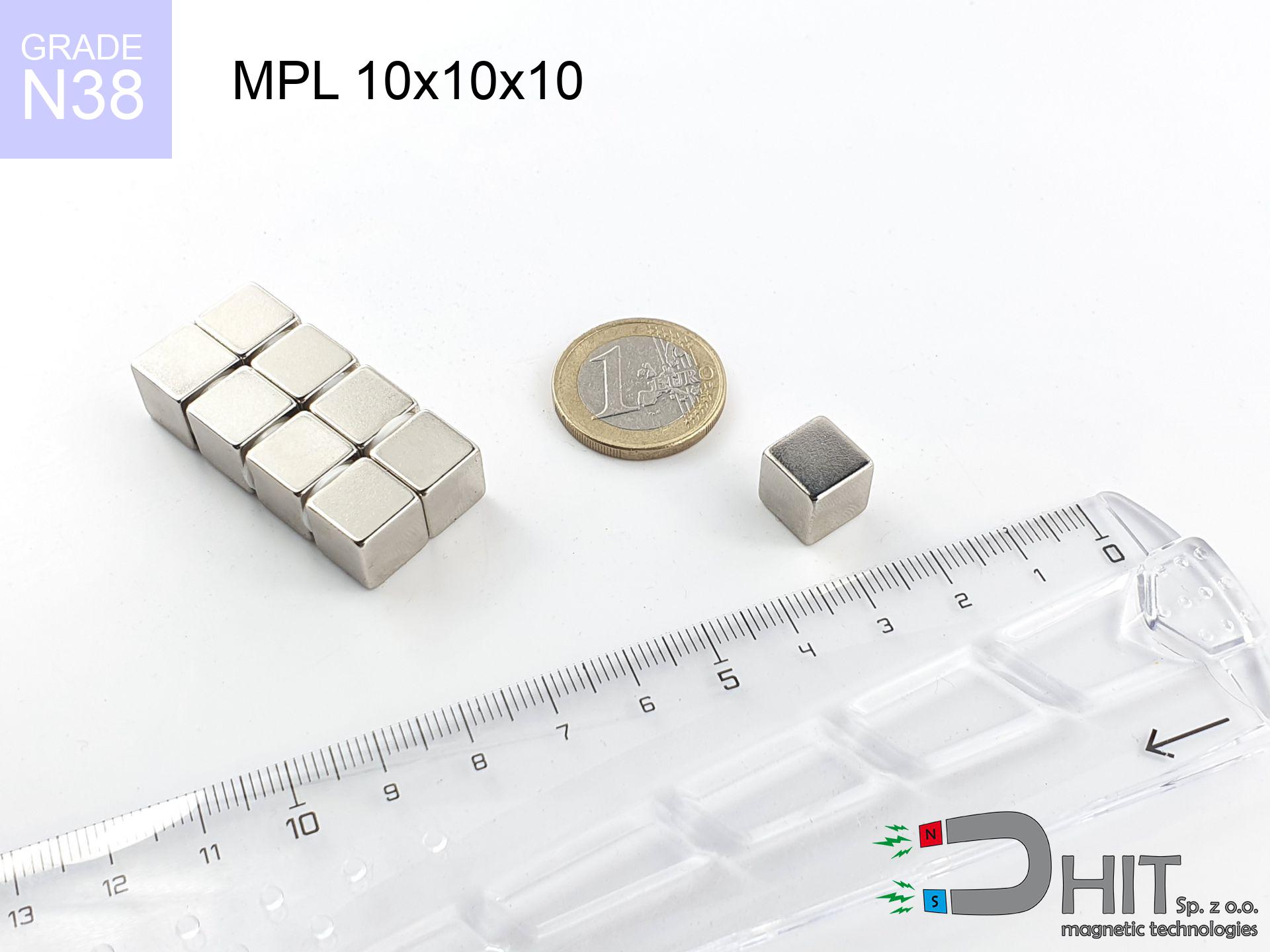
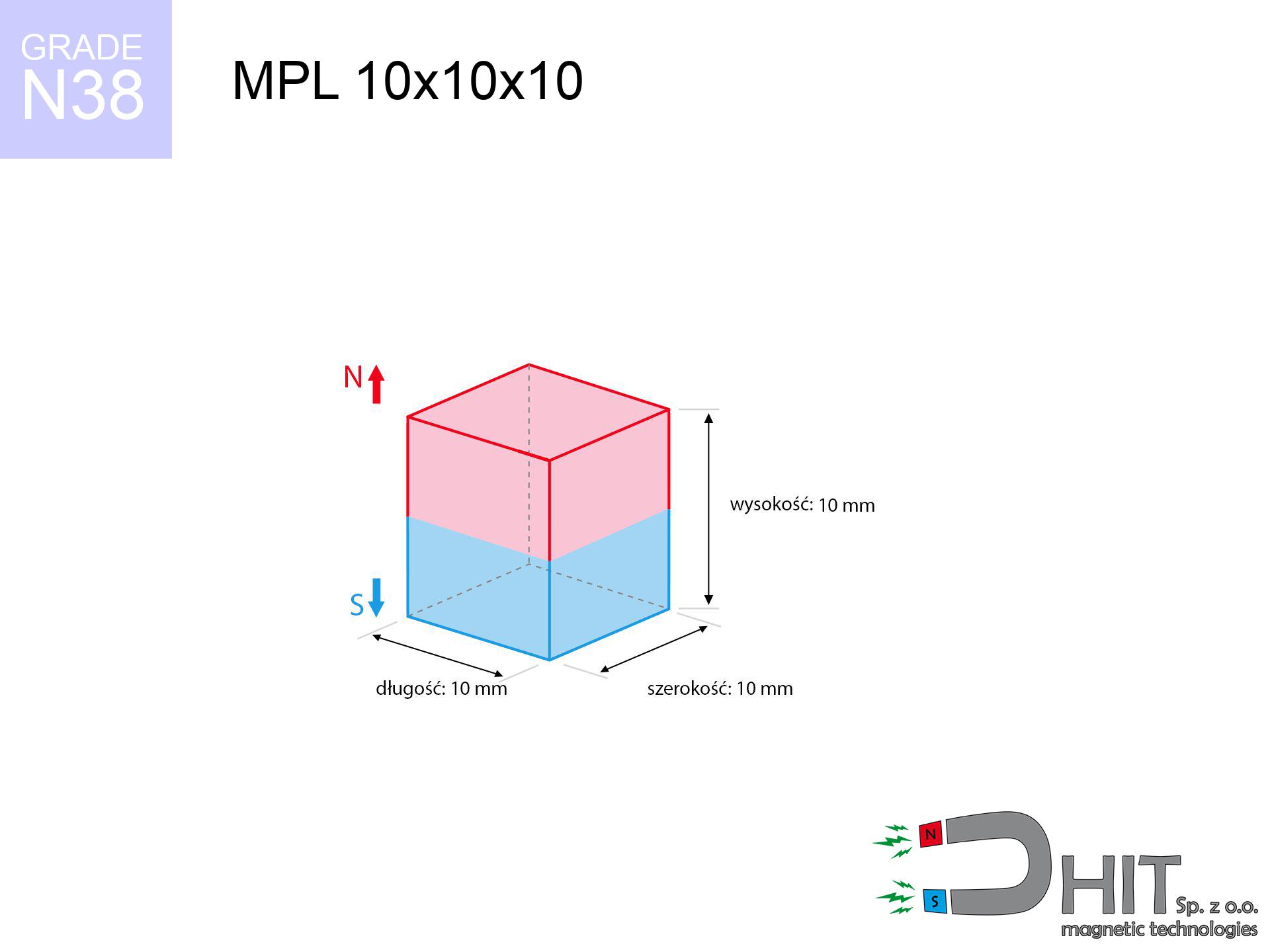
MPL 10x10x10 / N38 - lamellar magnet
lamellar magnet
Catalog no 020110
GTIN/EAN: 5906301811169
length
10 mm [±0,1 mm]
Width
10 mm [±0,1 mm]
Height
10 mm [±0,1 mm]
Weight
7.5 g
Magnetization Direction
↑ axial
Load capacity
3.84 kg / 37.71 N
Magnetic Induction
539.91 mT / 5399 Gs
Coating
[NiCuNi] Nickel
5.29 ZŁ with VAT / pcs + price for transport
4.30 ZŁ net + 23% VAT / pcs
bulk discounts:
Need more?
Call us
+48 888 99 98 98
or contact us through
request form
our website.
Force along with structure of neodymium magnets can be verified on our
magnetic calculator.
Orders submitted before 14:00 will be dispatched today!
Technical details - MPL 10x10x10 / N38 - lamellar magnet
Specification / characteristics - MPL 10x10x10 / N38 - lamellar magnet
| properties | values |
|---|---|
| Cat. no. | 020110 |
| GTIN/EAN | 5906301811169 |
| Production/Distribution | Dhit sp. z o.o. |
| Country of origin | Poland / China / Germany |
| Customs code | 85059029 |
| length | 10 mm [±0,1 mm] |
| Width | 10 mm [±0,1 mm] |
| Height | 10 mm [±0,1 mm] |
| Weight | 7.5 g |
| Magnetization Direction | ↑ axial |
| Load capacity ~ ? | 3.84 kg / 37.71 N |
| Magnetic Induction ~ ? | 539.91 mT / 5399 Gs |
| Coating | [NiCuNi] Nickel |
| Manufacturing Tolerance | ±0.1 mm |
Magnetic properties of material N38
| properties | values | units |
|---|---|---|
| remenance Br [min. - max.] ? | 12.2-12.6 | kGs |
| remenance Br [min. - max.] ? | 1220-1260 | mT |
| coercivity bHc ? | 10.8-11.5 | kOe |
| coercivity bHc ? | 860-915 | kA/m |
| actual internal force iHc | ≥ 12 | kOe |
| actual internal force iHc | ≥ 955 | kA/m |
| energy density [min. - max.] ? | 36-38 | BH max MGOe |
| energy density [min. - max.] ? | 287-303 | BH max KJ/m |
| max. temperature ? | ≤ 80 | °C |
Physical properties of sintered neodymium magnets Nd2Fe14B at 20°C
| properties | values | units |
|---|---|---|
| Vickers hardness | ≥550 | Hv |
| Density | ≥7.4 | g/cm3 |
| Curie Temperature TC | 312 - 380 | °C |
| Curie Temperature TF | 593 - 716 | °F |
| Specific resistance | 150 | μΩ⋅cm |
| Bending strength | 250 | MPa |
| Compressive strength | 1000~1100 | MPa |
| Thermal expansion parallel (∥) to orientation (M) | (3-4) x 10-6 | °C-1 |
| Thermal expansion perpendicular (⊥) to orientation (M) | -(1-3) x 10-6 | °C-1 |
| Young's modulus | 1.7 x 10⁴ | kg/mm² |
Physical analysis of the assembly - data
These values constitute the outcome of a engineering calculation. Results rely on models for the material Nd2Fe14B. Operational parameters might slightly differ from theoretical values. Use these calculations as a preliminary roadmap when designing systems.
Table 1: Static pull force (force vs distance) - characteristics
MPL 10x10x10 / N38
| Distance (mm) | Induction (Gauss) / mT | Pull Force (kg/lbs/g/N) | Risk Status |
|---|---|---|---|
| 0 mm |
5395 Gs
539.5 mT
|
3.84 kg / 8.47 pounds
3840.0 g / 37.7 N
|
strong |
| 1 mm |
4423 Gs
442.3 mT
|
2.58 kg / 5.69 pounds
2580.1 g / 25.3 N
|
strong |
| 2 mm |
3516 Gs
351.6 mT
|
1.63 kg / 3.60 pounds
1631.0 g / 16.0 N
|
low risk |
| 3 mm |
2751 Gs
275.1 mT
|
1.00 kg / 2.20 pounds
998.0 g / 9.8 N
|
low risk |
| 5 mm |
1671 Gs
167.1 mT
|
0.37 kg / 0.81 pounds
368.5 g / 3.6 N
|
low risk |
| 10 mm |
562 Gs
56.2 mT
|
0.04 kg / 0.09 pounds
41.7 g / 0.4 N
|
low risk |
| 15 mm |
244 Gs
24.4 mT
|
0.01 kg / 0.02 pounds
7.8 g / 0.1 N
|
low risk |
| 20 mm |
126 Gs
12.6 mT
|
0.00 kg / 0.00 pounds
2.1 g / 0.0 N
|
low risk |
| 30 mm |
46 Gs
4.6 mT
|
0.00 kg / 0.00 pounds
0.3 g / 0.0 N
|
low risk |
| 50 mm |
12 Gs
1.2 mT
|
0.00 kg / 0.00 pounds
0.0 g / 0.0 N
|
low risk |
Table 2: Shear capacity (wall)
MPL 10x10x10 / N38
| Distance (mm) | Friction coefficient | Pull Force (kg/lbs/g/N) |
|---|---|---|
| 0 mm | Stal (~0.2) |
0.77 kg / 1.69 pounds
768.0 g / 7.5 N
|
| 1 mm | Stal (~0.2) |
0.52 kg / 1.14 pounds
516.0 g / 5.1 N
|
| 2 mm | Stal (~0.2) |
0.33 kg / 0.72 pounds
326.0 g / 3.2 N
|
| 3 mm | Stal (~0.2) |
0.20 kg / 0.44 pounds
200.0 g / 2.0 N
|
| 5 mm | Stal (~0.2) |
0.07 kg / 0.16 pounds
74.0 g / 0.7 N
|
| 10 mm | Stal (~0.2) |
0.01 kg / 0.02 pounds
8.0 g / 0.1 N
|
| 15 mm | Stal (~0.2) |
0.00 kg / 0.00 pounds
2.0 g / 0.0 N
|
| 20 mm | Stal (~0.2) |
0.00 kg / 0.00 pounds
0.0 g / 0.0 N
|
| 30 mm | Stal (~0.2) |
0.00 kg / 0.00 pounds
0.0 g / 0.0 N
|
| 50 mm | Stal (~0.2) |
0.00 kg / 0.00 pounds
0.0 g / 0.0 N
|
Table 3: Vertical assembly (sliding) - vertical pull
MPL 10x10x10 / N38
| Surface type | Friction coefficient / % Mocy | Max load (kg/lbs/g/N) |
|---|---|---|
| Raw steel |
µ = 0.3
30% Nominalnej Siły
|
1.15 kg / 2.54 pounds
1152.0 g / 11.3 N
|
| Painted steel (standard) |
µ = 0.2
20% Nominalnej Siły
|
0.77 kg / 1.69 pounds
768.0 g / 7.5 N
|
| Oily/slippery steel |
µ = 0.1
10% Nominalnej Siły
|
0.38 kg / 0.85 pounds
384.0 g / 3.8 N
|
| Magnet with anti-slip rubber |
µ = 0.5
50% Nominalnej Siły
|
1.92 kg / 4.23 pounds
1920.0 g / 18.8 N
|
Table 4: Steel thickness (saturation) - sheet metal selection
MPL 10x10x10 / N38
| Steel thickness (mm) | % power | Real pull force (kg/lbs/g/N) |
|---|---|---|
| 0.5 mm |
|
0.38 kg / 0.85 pounds
384.0 g / 3.8 N
|
| 1 mm |
|
0.96 kg / 2.12 pounds
960.0 g / 9.4 N
|
| 2 mm |
|
1.92 kg / 4.23 pounds
1920.0 g / 18.8 N
|
| 3 mm |
|
2.88 kg / 6.35 pounds
2880.0 g / 28.3 N
|
| 5 mm |
|
3.84 kg / 8.47 pounds
3840.0 g / 37.7 N
|
| 10 mm |
|
3.84 kg / 8.47 pounds
3840.0 g / 37.7 N
|
| 11 mm |
|
3.84 kg / 8.47 pounds
3840.0 g / 37.7 N
|
| 12 mm |
|
3.84 kg / 8.47 pounds
3840.0 g / 37.7 N
|
Table 5: Working in heat (stability) - thermal limit
MPL 10x10x10 / N38
| Ambient temp. (°C) | Power loss | Remaining pull (kg/lbs/g/N) | Status |
|---|---|---|---|
| 20 °C | 0.0% |
3.84 kg / 8.47 pounds
3840.0 g / 37.7 N
|
OK |
| 40 °C | -2.2% |
3.76 kg / 8.28 pounds
3755.5 g / 36.8 N
|
OK |
| 60 °C | -4.4% |
3.67 kg / 8.09 pounds
3671.0 g / 36.0 N
|
OK |
| 80 °C | -6.6% |
3.59 kg / 7.91 pounds
3586.6 g / 35.2 N
|
|
| 100 °C | -28.8% |
2.73 kg / 6.03 pounds
2734.1 g / 26.8 N
|
Table 6: Magnet-Magnet interaction (attraction) - forces in the system
MPL 10x10x10 / N38
| Gap (mm) | Attraction (kg/lbs) (N-S) | Sliding Force (kg/lbs/g/N) | Repulsion (kg/lbs) (N-N) |
|---|---|---|---|
| 0 mm |
17.95 kg / 39.56 pounds
5 957 Gs
|
2.69 kg / 5.93 pounds
2692 g / 26.4 N
|
N/A |
| 1 mm |
14.86 kg / 32.77 pounds
9 821 Gs
|
2.23 kg / 4.92 pounds
2230 g / 21.9 N
|
13.38 kg / 29.49 pounds
~0 Gs
|
| 2 mm |
12.06 kg / 26.58 pounds
8 845 Gs
|
1.81 kg / 3.99 pounds
1809 g / 17.7 N
|
10.85 kg / 23.93 pounds
~0 Gs
|
| 3 mm |
9.64 kg / 21.26 pounds
7 909 Gs
|
1.45 kg / 3.19 pounds
1446 g / 14.2 N
|
8.68 kg / 19.13 pounds
~0 Gs
|
| 5 mm |
5.98 kg / 13.18 pounds
6 228 Gs
|
0.90 kg / 1.98 pounds
897 g / 8.8 N
|
5.38 kg / 11.86 pounds
~0 Gs
|
| 10 mm |
1.72 kg / 3.80 pounds
3 343 Gs
|
0.26 kg / 0.57 pounds
258 g / 2.5 N
|
1.55 kg / 3.42 pounds
~0 Gs
|
| 20 mm |
0.20 kg / 0.43 pounds
1 125 Gs
|
0.03 kg / 0.06 pounds
29 g / 0.3 N
|
0.18 kg / 0.39 pounds
~0 Gs
|
| 50 mm |
0.00 kg / 0.01 pounds
146 Gs
|
0.00 kg / 0.00 pounds
0 g / 0.0 N
|
0.00 kg / 0.00 pounds
~0 Gs
|
| 60 mm |
0.00 kg / 0.00 pounds
92 Gs
|
0.00 kg / 0.00 pounds
0 g / 0.0 N
|
0.00 kg / 0.00 pounds
~0 Gs
|
| 70 mm |
0.00 kg / 0.00 pounds
62 Gs
|
0.00 kg / 0.00 pounds
0 g / 0.0 N
|
0.00 kg / 0.00 pounds
~0 Gs
|
| 80 mm |
0.00 kg / 0.00 pounds
43 Gs
|
0.00 kg / 0.00 pounds
0 g / 0.0 N
|
0.00 kg / 0.00 pounds
~0 Gs
|
| 90 mm |
0.00 kg / 0.00 pounds
32 Gs
|
0.00 kg / 0.00 pounds
0 g / 0.0 N
|
0.00 kg / 0.00 pounds
~0 Gs
|
| 100 mm |
0.00 kg / 0.00 pounds
24 Gs
|
0.00 kg / 0.00 pounds
0 g / 0.0 N
|
0.00 kg / 0.00 pounds
~0 Gs
|
Table 7: Hazards (implants) - precautionary measures
MPL 10x10x10 / N38
| Object / Device | Limit (Gauss) / mT | Safe distance |
|---|---|---|
| Pacemaker | 5 Gs (0.5 mT) | 7.0 cm |
| Hearing aid | 10 Gs (1.0 mT) | 5.5 cm |
| Mechanical watch | 20 Gs (2.0 mT) | 4.5 cm |
| Phone / Smartphone | 40 Gs (4.0 mT) | 3.5 cm |
| Car key | 50 Gs (5.0 mT) | 3.0 cm |
| Payment card | 400 Gs (40.0 mT) | 1.5 cm |
| HDD hard drive | 600 Gs (60.0 mT) | 1.0 cm |
Table 8: Dynamics (kinetic energy) - collision effects
MPL 10x10x10 / N38
| Start from (mm) | Speed (km/h) | Energy (J) | Predicted outcome |
|---|---|---|---|
| 10 mm |
22.97 km/h
(6.38 m/s)
|
0.15 J | |
| 30 mm |
39.53 km/h
(10.98 m/s)
|
0.45 J | |
| 50 mm |
51.03 km/h
(14.17 m/s)
|
0.75 J | |
| 100 mm |
72.16 km/h
(20.05 m/s)
|
1.51 J |
Table 9: Surface protection spec
MPL 10x10x10 / N38
| Technical parameter | Value / Description |
|---|---|
| Coating type | [NiCuNi] Nickel |
| Layer structure | Nickel - Copper - Nickel |
| Layer thickness | 10-20 µm |
| Salt spray test (SST) ? | 24 h |
| Recommended environment | Indoors only (dry) |
Table 10: Electrical data (Flux)
MPL 10x10x10 / N38
| Parameter | Value | SI Unit / Description |
|---|---|---|
| Magnetic Flux | 5 504 Mx | 55.0 µWb |
| Pc Coefficient | 0.84 | High (Stable) |
Table 11: Submerged application
MPL 10x10x10 / N38
| Environment | Effective steel pull | Effect |
|---|---|---|
| Air (land) | 3.84 kg | Standard |
| Water (riverbed) |
4.40 kg
(+0.56 kg buoyancy gain)
|
+14.5% |
1. Sliding resistance
*Caution: On a vertical wall, the magnet retains just a fraction of its perpendicular strength.
2. Steel thickness impact
*Thin metal sheet (e.g. computer case) severely limits the holding force.
3. Heat tolerance
*For standard magnets, the critical limit is 80°C.
4. Demagnetization curve and operating point (B-H)
chart generated for the permeance coefficient Pc (Permeance Coefficient) = 0.84
This simulation demonstrates the magnetic stability of the selected magnet under specific geometric conditions. The solid red line represents the demagnetization curve (material potential), while the dashed blue line is the load line based on the magnet's geometry. The Pc (Permeance Coefficient), also known as the load line slope, is a dimensionless value that describes the relationship between the magnet's shape and its magnetic stability. The intersection of these two lines (the black dot) is the operating point — it determines the actual magnetic flux density generated by the magnet in this specific configuration. A higher Pc value means the magnet is more 'slender' (tall relative to its area), resulting in a higher operating point and better resistance to irreversible demagnetization caused by external fields or temperature. A value of 0.42 is relatively low (typical for flat magnets), meaning the operating point is closer to the 'knee' of the curve — caution is advised when operating at temperatures near the maximum limit to avoid strength loss.
Chemical composition
| iron (Fe) | 64% – 68% |
| neodymium (Nd) | 29% – 32% |
| boron (B) | 1.1% – 1.2% |
| dysprosium (Dy) | 0.5% – 2.0% |
| coating (Ni-Cu-Ni) | < 0.05% |
Environmental data
| recyclability (EoL) | 100% |
| recycled raw materials | ~10% (pre-cons) |
| carbon footprint | low / zredukowany |
| waste code (EWC) | 16 02 16 |
Other proposals
![UMGZ 20x15x7 [M4] GZ / N38 - magnetic holder external thread](https://cdn3.dhit.pl/graphics/products/um-20x15x7-m4-gz-vaf.jpg "UMGZ 20x15x7 [M4] GZ / N38 - magnetic holder external thread")

![UI 40x12x7 [CA] - badge holder](https://cdn3.dhit.pl/graphics/products/ui40x12x7-vop.jpg "UI 40x12x7 [CA] - badge holder")
![UMH 32x8x46 [M6] / N38 - magnetic holder with hook](https://cdn3.dhit.pl/graphics/products/umh-32x8x46-m6-xov.jpg "UMH 32x8x46 [M6] / N38 - magnetic holder with hook")
Pros as well as cons of rare earth magnets.
Strengths
- They virtually do not lose power, because even after 10 years the decline in efficiency is only ~1% (in laboratory conditions),
- Neodymium magnets are distinguished by extremely resistant to loss of magnetic properties caused by magnetic disturbances,
- Thanks to the elegant finish, the surface of Ni-Cu-Ni, gold-plated, or silver gives an modern appearance,
- Magnets have impressive magnetic induction on the outer side,
- Due to their durability and thermal resistance, neodymium magnets can operate (depending on the form) even at high temperatures reaching 230°C or more...
- Possibility of exact modeling as well as optimizing to complex conditions,
- Significant place in high-tech industry – they serve a role in magnetic memories, motor assemblies, precision medical tools, and multitasking production systems.
- Thanks to concentrated force, small magnets offer high operating force, with minimal size,
Weaknesses
- Brittleness is one of their disadvantages. Upon strong impact they can break. We recommend keeping them in a steel housing, which not only secures them against impacts but also raises their durability
- We warn that neodymium magnets can lose their strength at high temperatures. To prevent this, we suggest our specialized [AH] magnets, which work effectively even at 230°C.
- Magnets exposed to a humid environment can rust. Therefore while using outdoors, we suggest using waterproof magnets made of rubber, plastic or other material resistant to moisture
- We suggest a housing - magnetic mechanism, due to difficulties in producing threads inside the magnet and complicated shapes.
- Health risk to health – tiny shards of magnets pose a threat, if swallowed, which gains importance in the context of child safety. It is also worth noting that small components of these products are able to be problematic in diagnostics medical in case of swallowing.
- Higher cost of purchase is one of the disadvantages compared to ceramic magnets, especially in budget applications
Pull force analysis
Maximum holding power of the magnet – what affects it?
- using a plate made of high-permeability steel, serving as a ideal flux conductor
- whose transverse dimension is min. 10 mm
- with an ideally smooth touching surface
- under conditions of gap-free contact (metal-to-metal)
- for force acting at a right angle (pull-off, not shear)
- at temperature approx. 20 degrees Celsius
Impact of factors on magnetic holding capacity in practice
- Clearance – existence of foreign body (rust, tape, gap) interrupts the magnetic circuit, which lowers capacity rapidly (even by 50% at 0.5 mm).
- Pull-off angle – remember that the magnet holds strongest perpendicularly. Under sliding down, the holding force drops drastically, often to levels of 20-30% of the maximum value.
- Substrate thickness – for full efficiency, the steel must be sufficiently thick. Paper-thin metal restricts the attraction force (the magnet "punches through" it).
- Material type – the best choice is high-permeability steel. Hardened steels may have worse magnetic properties.
- Surface finish – ideal contact is possible only on polished steel. Rough texture create air cushions, weakening the magnet.
- Heat – NdFeB sinters have a sensitivity to temperature. At higher temperatures they lose power, and in frost they can be stronger (up to a certain limit).
Lifting capacity was assessed by applying a polished steel plate of optimal thickness (min. 20 mm), under vertically applied force, however under parallel forces the lifting capacity is smaller. Moreover, even a slight gap between the magnet and the plate reduces the holding force.
H&S for magnets
Handling rules
Before starting, check safety instructions. Sudden snapping can destroy the magnet or injure your hand. Think ahead.
GPS Danger
GPS units and mobile phones are highly sensitive to magnetic fields. Close proximity with a strong magnet can ruin the internal compass in your phone.
Warning for allergy sufferers
Nickel alert: The Ni-Cu-Ni coating contains nickel. If redness appears, immediately stop working with magnets and use protective gear.
Mechanical processing
Machining of neodymium magnets poses a fire hazard. Neodymium dust reacts violently with oxygen and is difficult to extinguish.
Danger to pacemakers
Individuals with a heart stimulator must keep an safe separation from magnets. The magnetism can interfere with the functioning of the implant.
Protective goggles
NdFeB magnets are ceramic materials, meaning they are prone to chipping. Impact of two magnets will cause them shattering into small pieces.
Operating temperature
Avoid heat. NdFeB magnets are sensitive to heat. If you require operation above 80°C, ask us about HT versions (H, SH, UH).
Product not for children
Adult use only. Small elements pose a choking risk, leading to severe trauma. Store out of reach of children and animals.
Keep away from computers
Equipment safety: Strong magnets can damage data carriers and delicate electronics (heart implants, hearing aids, mechanical watches).
Serious injuries
Protect your hands. Two powerful magnets will join instantly with a force of several hundred kilograms, crushing anything in their path. Exercise extreme caution!
Tabela kosztu i czasu dostawy
Płatność przed wysyłką:

GLS kurier
Przesyłka będzie u Ciebie za 2-3 dni
14.99 ZŁ

InPost Paczkomaty 24/7
Przesyłka będzie u Ciebie za 1-2 dni
12.30 ZŁ
Płatność przy odbiorze (pobranie):
GLS kurier
Przesyłka będzie u Ciebie za 1-2 dni
23.00 ZŁ
Rate the product
Your rating