

MP 60x20x5 / N38 - ring magnet
ring magnet
Catalog no 030204
GTIN/EAN: 5906301812210
Diameter
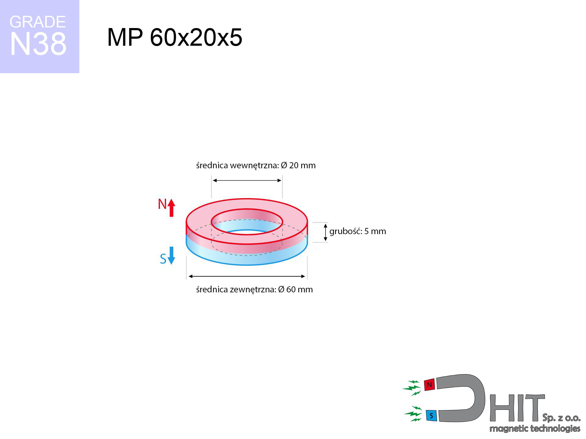
60 mm [±0,1 mm]
internal diameter Ø
20 mm [±0,1 mm]
Height
5 mm [±0,1 mm]
Weight
94.25 g
Magnetization Direction
↑ axial
Load capacity
9.41 kg / 92.27 N
Magnetic Induction
101.92 mT / 1019 Gs
Coating
[NiCuNi] Nickel
47.99 ZŁ with VAT / pcs + price for transport
39.02 ZŁ net + 23% VAT / pcs
bulk discounts:
Need more?Engineering report for this magnet
Full PDF analysis: pull and shear force, effect of distance, temperature and plate thickness, safety distances and the demagnetization curve.
Call us now
+48 22 499 98 98
if you prefer contact us via
our online form
the contact form page.
Specifications as well as form of magnets can be estimated on our
modular calculator.
Same-day processing for orders placed before 14:00.
Technical - MP 60x20x5 / N38 - ring magnet
Specification / characteristics - MP 60x20x5 / N38 - ring magnet
| properties | values |
|---|---|
| Cat. no. | 030204 |
| GTIN/EAN | 5906301812210 |
| Production/Distribution | Dhit sp. z o.o. |
| Country of origin | Poland / China / Germany |
| Customs code | 85059029 |
| Diameter | 60 mm [±0,1 mm] |
| internal diameter Ø | 20 mm [±0,1 mm] |
| Height | 5 mm [±0,1 mm] |
| Weight | 94.25 g |
| Magnetization Direction | ↑ axial |
| Load capacity ~ ? | 9.41 kg / 92.27 N |
| Magnetic Induction ~ ? | 101.92 mT / 1019 Gs |
| Coating | [NiCuNi] Nickel |
| Manufacturing Tolerance | ±0.1 mm |
Magnetic properties of material N38
| properties | values | units |
|---|---|---|
| remenance Br [min. - max.] ? | 12.2-12.6 | kGs |
| remenance Br [min. - max.] ? | 1220-1260 | mT |
| coercivity bHc ? | 10.8-11.5 | kOe |
| coercivity bHc ? | 860-915 | kA/m |
| actual internal force iHc | ≥ 12 | kOe |
| actual internal force iHc | ≥ 955 | kA/m |
| energy density [min. - max.] ? | 36-38 | BH max MGOe |
| energy density [min. - max.] ? | 287-303 | BH max KJ/m |
| max. temperature ? | ≤ 80 | °C |
Physical properties of sintered neodymium magnets Nd2Fe14B at 20°C
| properties | values | units |
|---|---|---|
| Vickers hardness | ≥550 | Hv |
| Density | ≥7.4 | g/cm3 |
| Curie Temperature TC | 312 - 380 | °C |
| Curie Temperature TF | 593 - 716 | °F |
| Specific resistance | 150 | μΩ⋅cm |
| Bending strength | 250 | MPa |
| Compressive strength | 1000~1100 | MPa |
| Thermal expansion parallel (∥) to orientation (M) | (3-4) x 10-6 | °C-1 |
| Thermal expansion perpendicular (⊥) to orientation (M) | -(1-3) x 10-6 | °C-1 |
| Young's modulus | 1.7 x 10⁴ | kg/mm² |
Physical analysis of the assembly - data
The following values constitute the result of a mathematical simulation. Values were calculated on models for the class Nd2Fe14B. Operational parameters may differ from theoretical values. Use these data as a reference point for designers.
Table 1: Static force (pull vs distance) - interaction chart
MP 60x20x5 / N38
| Distance (mm) | Induction (Gauss) / mT | Pull Force (kg/lbs/g/N) | Risk Status |
|---|---|---|---|
| 0 mm |
4541 Gs
454.1 mT
|
9.41 kg / 20.75 lbs
9410.0 g / 92.3 N
|
medium risk |
| 1 mm |
4400 Gs
440.0 mT
|
8.83 kg / 19.47 lbs
8832.4 g / 86.6 N
|
medium risk |
| 2 mm |
4254 Gs
425.4 mT
|
8.26 kg / 18.21 lbs
8258.2 g / 81.0 N
|
medium risk |
| 3 mm |
4107 Gs
410.7 mT
|
7.70 kg / 16.97 lbs
7697.5 g / 75.5 N
|
medium risk |
| 5 mm |
3812 Gs
381.2 mT
|
6.63 kg / 14.62 lbs
6630.0 g / 65.0 N
|
medium risk |
| 10 mm |
3097 Gs
309.7 mT
|
4.38 kg / 9.65 lbs
4375.1 g / 42.9 N
|
medium risk |
| 15 mm |
2463 Gs
246.3 mT
|
2.77 kg / 6.10 lbs
2767.8 g / 27.2 N
|
medium risk |
| 20 mm |
1939 Gs
193.9 mT
|
1.72 kg / 3.78 lbs
1715.2 g / 16.8 N
|
low risk |
| 30 mm |
1202 Gs
120.2 mT
|
0.66 kg / 1.45 lbs
659.2 g / 6.5 N
|
low risk |
| 50 mm |
509 Gs
50.9 mT
|
0.12 kg / 0.26 lbs
118.0 g / 1.2 N
|
low risk |
Table 2: Shear capacity (wall)
MP 60x20x5 / N38
| Distance (mm) | Friction coefficient | Pull Force (kg/lbs/g/N) |
|---|---|---|
| 0 mm | Stal (~0.2) |
1.88 kg / 4.15 lbs
1882.0 g / 18.5 N
|
| 1 mm | Stal (~0.2) |
1.77 kg / 3.89 lbs
1766.0 g / 17.3 N
|
| 2 mm | Stal (~0.2) |
1.65 kg / 3.64 lbs
1652.0 g / 16.2 N
|
| 3 mm | Stal (~0.2) |
1.54 kg / 3.40 lbs
1540.0 g / 15.1 N
|
| 5 mm | Stal (~0.2) |
1.33 kg / 2.92 lbs
1326.0 g / 13.0 N
|
| 10 mm | Stal (~0.2) |
0.88 kg / 1.93 lbs
876.0 g / 8.6 N
|
| 15 mm | Stal (~0.2) |
0.55 kg / 1.22 lbs
554.0 g / 5.4 N
|
| 20 mm | Stal (~0.2) |
0.34 kg / 0.76 lbs
344.0 g / 3.4 N
|
| 30 mm | Stal (~0.2) |
0.13 kg / 0.29 lbs
132.0 g / 1.3 N
|
| 50 mm | Stal (~0.2) |
0.02 kg / 0.05 lbs
24.0 g / 0.2 N
|
Table 3: Vertical assembly (shearing) - behavior on slippery surfaces
MP 60x20x5 / N38
| Surface type | Friction coefficient / % Mocy | Max load (kg/lbs/g/N) |
|---|---|---|
| Raw steel |
µ = 0.3
30% Nominalnej Siły
|
2.82 kg / 6.22 lbs
2823.0 g / 27.7 N
|
| Painted steel (standard) |
µ = 0.2
20% Nominalnej Siły
|
1.88 kg / 4.15 lbs
1882.0 g / 18.5 N
|
| Oily/slippery steel |
µ = 0.1
10% Nominalnej Siły
|
0.94 kg / 2.07 lbs
941.0 g / 9.2 N
|
| Magnet with anti-slip rubber |
µ = 0.5
50% Nominalnej Siły
|
4.71 kg / 10.37 lbs
4705.0 g / 46.2 N
|
Table 4: Steel thickness (saturation) - sheet metal selection
MP 60x20x5 / N38
| Steel thickness (mm) | % power | Real pull force (kg/lbs/g/N) |
|---|---|---|
| 0.5 mm |
|
0.94 kg / 2.07 lbs
941.0 g / 9.2 N
|
| 1 mm |
|
2.35 kg / 5.19 lbs
2352.5 g / 23.1 N
|
| 2 mm |
|
4.71 kg / 10.37 lbs
4705.0 g / 46.2 N
|
| 3 mm |
|
7.06 kg / 15.56 lbs
7057.5 g / 69.2 N
|
| 5 mm |
|
9.41 kg / 20.75 lbs
9410.0 g / 92.3 N
|
| 10 mm |
|
9.41 kg / 20.75 lbs
9410.0 g / 92.3 N
|
| 11 mm |
|
9.41 kg / 20.75 lbs
9410.0 g / 92.3 N
|
| 12 mm |
|
9.41 kg / 20.75 lbs
9410.0 g / 92.3 N
|
Table 5: Thermal resistance (material behavior) - thermal limit
MP 60x20x5 / N38
| Ambient temp. (°C) | Power loss | Remaining pull (kg/lbs/g/N) | Status |
|---|---|---|---|
| 20 °C | 0.0% |
9.41 kg / 20.75 lbs
9410.0 g / 92.3 N
|
OK |
| 40 °C | -2.2% |
9.20 kg / 20.29 lbs
9203.0 g / 90.3 N
|
OK |
| 60 °C | -4.4% |
9.00 kg / 19.83 lbs
8996.0 g / 88.3 N
|
OK |
| 80 °C | -6.6% |
8.79 kg / 19.38 lbs
8788.9 g / 86.2 N
|
|
| 100 °C | -28.8% |
6.70 kg / 14.77 lbs
6699.9 g / 65.7 N
|
Table 6: Magnet-Magnet interaction (attraction) - field range
MP 60x20x5 / N38
| Gap (mm) | Attraction (kg/lbs) (N-S) | Lateral Force (kg/lbs/g/N) | Repulsion (kg/lbs) (N-N) |
|---|---|---|---|
| 0 mm |
303.46 kg / 669.01 lbs
5 621 Gs
|
45.52 kg / 100.35 lbs
45519 g / 446.5 N
|
N/A |
| 1 mm |
294.21 kg / 648.62 lbs
8 943 Gs
|
44.13 kg / 97.29 lbs
44132 g / 432.9 N
|
264.79 kg / 583.76 lbs
~0 Gs
|
| 2 mm |
284.83 kg / 627.94 lbs
8 800 Gs
|
42.72 kg / 94.19 lbs
42725 g / 419.1 N
|
256.35 kg / 565.15 lbs
~0 Gs
|
| 3 mm |
275.53 kg / 607.43 lbs
8 655 Gs
|
41.33 kg / 91.11 lbs
41329 g / 405.4 N
|
247.97 kg / 546.69 lbs
~0 Gs
|
| 5 mm |
257.21 kg / 567.06 lbs
8 362 Gs
|
38.58 kg / 85.06 lbs
38582 g / 378.5 N
|
231.49 kg / 510.35 lbs
~0 Gs
|
| 10 mm |
213.81 kg / 471.36 lbs
7 624 Gs
|
32.07 kg / 70.70 lbs
32071 g / 314.6 N
|
192.43 kg / 424.23 lbs
~0 Gs
|
| 20 mm |
141.09 kg / 311.05 lbs
6 193 Gs
|
21.16 kg / 46.66 lbs
21164 g / 207.6 N
|
126.98 kg / 279.95 lbs
~0 Gs
|
| 50 mm |
34.15 kg / 75.30 lbs
3 047 Gs
|
5.12 kg / 11.29 lbs
5123 g / 50.3 N
|
30.74 kg / 67.77 lbs
~0 Gs
|
| 60 mm |
21.26 kg / 46.87 lbs
2 404 Gs
|
3.19 kg / 7.03 lbs
3189 g / 31.3 N
|
19.13 kg / 42.18 lbs
~0 Gs
|
| 70 mm |
13.43 kg / 29.61 lbs
1 911 Gs
|
2.01 kg / 4.44 lbs
2015 g / 19.8 N
|
12.09 kg / 26.65 lbs
~0 Gs
|
| 80 mm |
8.65 kg / 19.06 lbs
1 533 Gs
|
1.30 kg / 2.86 lbs
1297 g / 12.7 N
|
7.78 kg / 17.16 lbs
~0 Gs
|
| 90 mm |
5.68 kg / 12.52 lbs
1 243 Gs
|
0.85 kg / 1.88 lbs
852 g / 8.4 N
|
5.11 kg / 11.27 lbs
~0 Gs
|
| 100 mm |
3.81 kg / 8.39 lbs
1 017 Gs
|
0.57 kg / 1.26 lbs
571 g / 5.6 N
|
3.43 kg / 7.55 lbs
~0 Gs
|
Table 7: Protective zones (electronics) - precautionary measures
MP 60x20x5 / N38
| Object / Device | Limit (Gauss) / mT | Safe distance |
|---|---|---|
| Pacemaker | 5 Gs (0.5 mT) | 31.5 cm |
| Hearing aid | 10 Gs (1.0 mT) | 24.5 cm |
| Timepiece | 20 Gs (2.0 mT) | 19.5 cm |
| Mobile device | 40 Gs (4.0 mT) | 15.0 cm |
| Remote | 50 Gs (5.0 mT) | 14.0 cm |
| Payment card | 400 Gs (40.0 mT) | 6.0 cm |
| HDD hard drive | 600 Gs (60.0 mT) | 5.0 cm |
Table 8: Collisions (cracking risk) - collision effects
MP 60x20x5 / N38
| Start from (mm) | Speed (km/h) | Energy (J) | Predicted outcome |
|---|---|---|---|
| 10 mm |
12.67 km/h
(3.52 m/s)
|
0.58 J | |
| 30 mm |
18.20 km/h
(5.06 m/s)
|
1.20 J | |
| 50 mm |
22.71 km/h
(6.31 m/s)
|
1.88 J | |
| 100 mm |
31.88 km/h
(8.85 m/s)
|
3.70 J |
Table 9: Corrosion resistance
MP 60x20x5 / N38
| Technical parameter | Value / Description |
|---|---|
| Coating type | [NiCuNi] Nickel |
| Layer structure | Nickel - Copper - Nickel |
| Layer thickness | 10-20 µm |
| Salt spray test (SST) ? | 24 h |
| Recommended environment | Indoors only (dry) |
Table 10: Electrical data (Pc)
MP 60x20x5 / N38
| Parameter | Value | SI Unit / Description |
|---|---|---|
| Magnetic Flux | 109 640 Mx | 1096.4 µWb |
| Pc Coefficient | 0.62 | High (Stable) |
Table 11: Underwater work (magnet fishing)
MP 60x20x5 / N38
| Environment | Effective steel pull | Effect |
|---|---|---|
| Air (land) | 9.41 kg | Standard |
| Water (riverbed) |
10.77 kg
(+1.36 kg buoyancy gain)
|
+14.5% |
1. Vertical hold
*Caution: On a vertical wall, the magnet holds only approx. 20-30% of its max power.
2. Efficiency vs thickness
*Thin metal sheet (e.g. 0.5mm PC case) drastically weakens the holding force.
3. Temperature resistance
*For standard magnets, the max working temp is 80°C.
4. Demagnetization curve and operating point (B-H)
chart generated for the permeance coefficient Pc (Permeance Coefficient) = 0.62
The chart above illustrates the magnetic characteristics of the material within the second quadrant of the hysteresis loop. The solid red line represents the demagnetization curve (material potential), while the dashed blue line is the load line based on the magnet's geometry. The Pc (Permeance Coefficient), also known as the load line slope, is a dimensionless value that describes the relationship between the magnet's shape and its magnetic stability. The intersection of these two lines (the black dot) is the operating point — it determines the actual magnetic flux density generated by the magnet in this specific configuration. A higher Pc value means the magnet is more 'slender' (tall relative to its area), resulting in a higher operating point and better resistance to irreversible demagnetization caused by external fields or temperature. A value of 0.42 is relatively low (typical for flat magnets), meaning the operating point is closer to the 'knee' of the curve — caution is advised when operating at temperatures near the maximum limit to avoid strength loss.
Chemical composition
| iron (Fe) | 64% – 68% |
| neodymium (Nd) | 29% – 32% |
| boron (B) | 1.1% – 1.2% |
| dysprosium (Dy) | 0.5% – 2.0% |
| coating (Ni-Cu-Ni) | < 0.05% |
Ecology and recycling (GPSR)
| recyclability (EoL) | 100% |
| recycled raw materials | ~10% (pre-cons) |
| carbon footprint | low / zredukowany |
| waste code (EWC) | 16 02 16 |
Check out also offers
![UMP 75x25 [M10x3] GW F200 PLATINIUM / N52 - search holder](https://cdn3.dhit.pl/graphics/products/ump-75x25-m10x3-gw-f200-platinium-tav.jpg "UMP 75x25 [M10x3] GW F200 PLATINIUM / N52 - search holder")


Strengths and weaknesses of rare earth magnets.
Strengths
- They do not lose power, even over around 10 years – the reduction in lifting capacity is only ~1% (theoretically),
- They are extremely resistant to demagnetization induced by external magnetic fields,
- Thanks to the shiny finish, the coating of nickel, gold-plated, or silver-plated gives an professional appearance,
- Magnets exhibit maximum magnetic induction on the active area,
- Due to their durability and thermal resistance, neodymium magnets are capable of operate (depending on the shape) even at high temperatures reaching 230°C or more...
- In view of the potential of precise molding and customization to unique projects, NdFeB magnets can be manufactured in a broad palette of shapes and sizes, which amplifies use scope,
- Huge importance in modern industrial fields – they are commonly used in mass storage devices, electromotive mechanisms, diagnostic systems, as well as modern systems.
- Relatively small size with high pulling force – neodymium magnets offer strong magnetic field in compact dimensions, which enables their usage in compact constructions
Weaknesses
- At very strong impacts they can break, therefore we advise placing them in special holders. A metal housing provides additional protection against damage and increases the magnet's durability.
- We warn that neodymium magnets can lose their strength at high temperatures. To prevent this, we suggest our specialized [AH] magnets, which work effectively even at 230°C.
- Due to the susceptibility of magnets to corrosion in a humid environment, we advise using waterproof magnets made of rubber, plastic or other material stable to moisture, in case of application outdoors
- We suggest casing - magnetic mechanism, due to difficulties in creating nuts inside the magnet and complex shapes.
- Potential hazard related to microscopic parts of magnets are risky, when accidentally swallowed, which is particularly important in the context of child safety. Furthermore, small components of these products are able to disrupt the diagnostic process medical in case of swallowing.
- Due to expensive raw materials, their price exceeds standard values,
Lifting parameters
Optimal lifting capacity of a neodymium magnet – what it depends on?
- on a plate made of mild steel, optimally conducting the magnetic flux
- possessing a thickness of min. 10 mm to ensure full flux closure
- characterized by smoothness
- without the slightest air gap between the magnet and steel
- under axial application of breakaway force (90-degree angle)
- at ambient temperature room level
Determinants of lifting force in real conditions
- Gap (betwixt the magnet and the metal), because even a microscopic distance (e.g. 0.5 mm) results in a drastic drop in lifting capacity by up to 50% (this also applies to paint, rust or dirt).
- Force direction – note that the magnet holds strongest perpendicularly. Under sliding down, the capacity drops significantly, often to levels of 20-30% of the maximum value.
- Element thickness – to utilize 100% power, the steel must be adequately massive. Thin sheet restricts the attraction force (the magnet "punches through" it).
- Material composition – different alloys attracts identically. Alloy additives weaken the attraction effect.
- Surface condition – ground elements ensure maximum contact, which increases force. Uneven metal reduce efficiency.
- Temperature – heating the magnet results in weakening of force. Check the maximum operating temperature for a given model.
Holding force was checked on a smooth steel plate of 20 mm thickness, when the force acted perpendicularly, in contrast under shearing force the holding force is lower. In addition, even a slight gap between the magnet’s surface and the plate decreases the holding force.
Precautions when working with neodymium magnets
Maximum temperature
Keep cool. Neodymium magnets are susceptible to heat. If you need resistance above 80°C, ask us about special high-temperature series (H, SH, UH).
Nickel allergy
A percentage of the population have a sensitization to nickel, which is the typical protective layer for neodymium magnets. Prolonged contact can result in a rash. We recommend use protective gloves.
Medical interference
Warning for patients: Strong magnetic fields disrupt medical devices. Maintain at least 30 cm distance or request help to handle the magnets.
Conscious usage
Before use, read the rules. Uncontrolled attraction can break the magnet or hurt your hand. Think ahead.
Physical harm
Big blocks can crush fingers in a fraction of a second. Never put your hand betwixt two strong magnets.
Cards and drives
Avoid bringing magnets close to a purse, laptop, or TV. The magnetism can destroy these devices and wipe information from cards.
Eye protection
Neodymium magnets are sintered ceramics, meaning they are prone to chipping. Clashing of two magnets leads to them cracking into shards.
Fire warning
Combustion risk: Rare earth powder is highly flammable. Avoid machining magnets without safety gear as this risks ignition.
This is not a toy
Product intended for adults. Small elements can be swallowed, causing intestinal necrosis. Store out of reach of kids and pets.
Phone sensors
A powerful magnetic field interferes with the functioning of magnetometers in smartphones and navigation systems. Do not bring magnets near a smartphone to prevent damaging the sensors.
Tabela kosztu i czasu dostawy
Płatność przed wysyłką:

GLS kurier
Przesyłka będzie u Ciebie za 2-3 dni
14.99 ZŁ

InPost Paczkomaty 24/7
Przesyłka będzie u Ciebie za 1-2 dni
12.30 ZŁ
Płatność przy odbiorze (pobranie):
GLS kurier
Przesyłka będzie u Ciebie za 1-2 dni
23.00 ZŁ
Rate the product
Your rating