
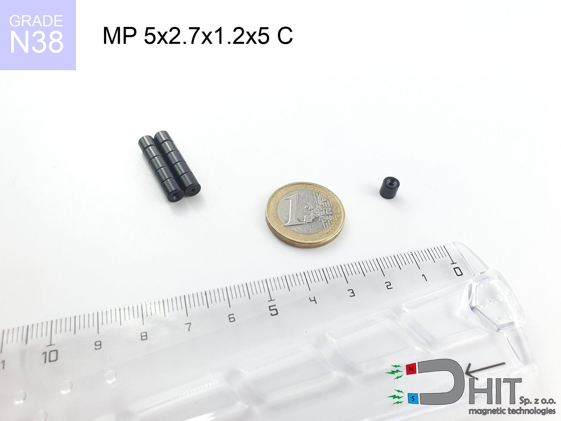
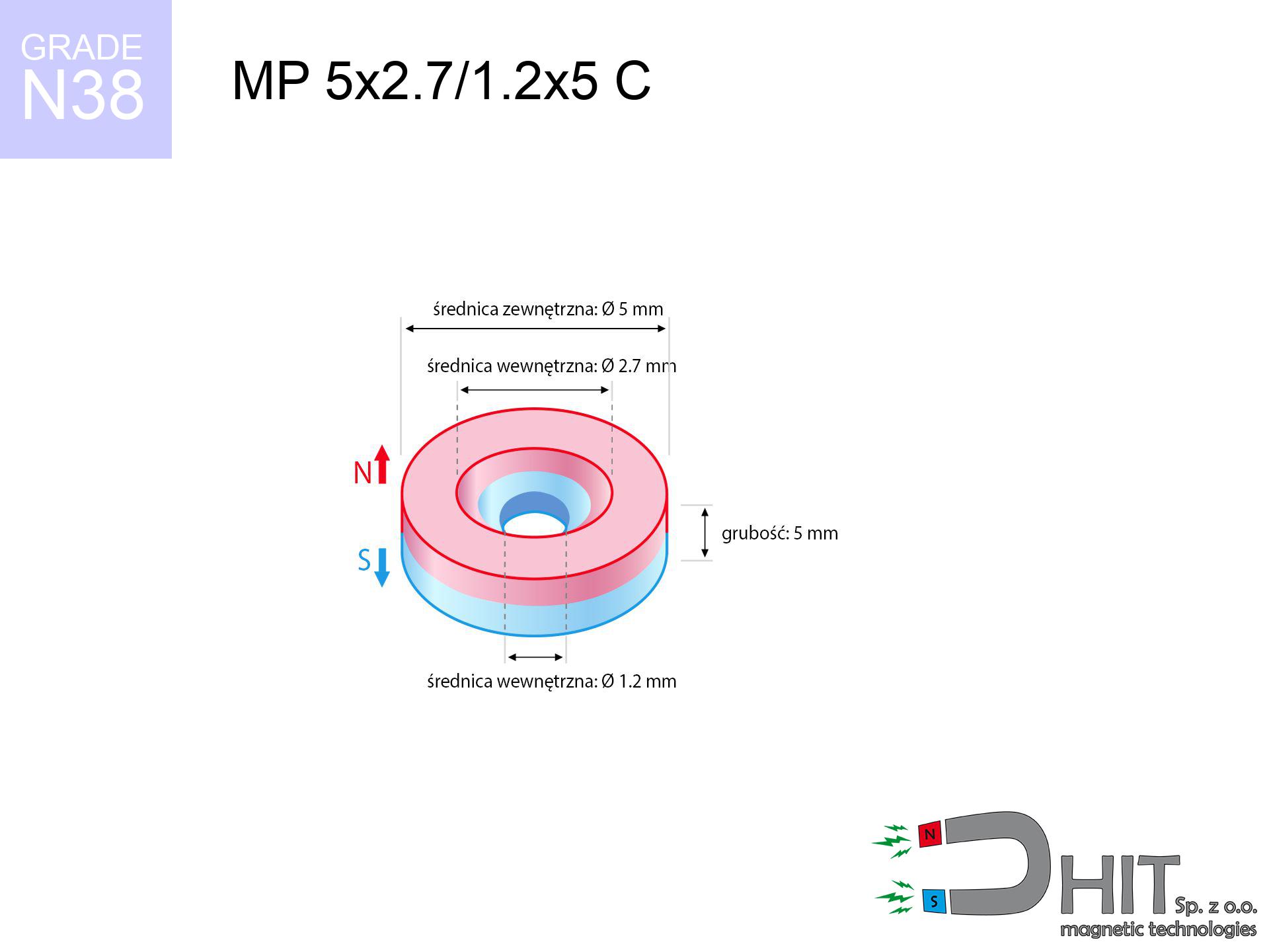
MP 5x2.7/1.2x5 C / N38 - ring magnet
ring magnet
Catalog no 030201
GTIN/EAN: 5906301812180
- Diameter
- 5 mm [±0,1 mm]
- internal diameter Ø
- 2.7/1.2 mm [±0,1 mm]
- Height
- 5 mm [±0,1 mm]
- Weight
- 0.69 g
- Magnetization Direction
- ↑ axial
- Coating
- [NiCuNi] Nickel
0.836 zł with VAT / pcs + price for transport
0.680 zł net + 23% VAT / pcs
bulk discounts:
Need more?Engineering report for this magnet
Full PDF analysis: pull and shear force, effect of distance, temperature and plate thickness, safety distances and the demagnetization curve.
Contact us by phone
+48 22 499 98 98
or send us a note by means of
inquiry form
the contact page.
Strength along with appearance of neodymium magnets can be calculated using our
force calculator.
Same-day shipping for orders placed before 14:00.
Technical of the product - MP 5x2.7/1.2x5 C / N38 - ring magnet
Specification / characteristics - MP 5x2.7/1.2x5 C / N38 - ring magnet
| properties | values |
|---|---|
| Cat. no. | 030201 |
| GTIN/EAN | 5906301812180 |
| Production/Distribution | Dhit sp. z o.o. |
| Country of origin | Poland / China / Germany |
| Customs code | 85059029 |
| Diameter | 5 mm [±0,1 mm] |
| internal diameter Ø | 2.7/1.2 mm [±0,1 mm] |
| Height | 5 mm [±0,1 mm] |
| Weight | 0.69 g |
| Magnetization Direction | ↑ axial |
| Load capacity ~ ? | 0.75 kg / 7.31 N |
| Magnetic Induction ~ ? | 553.14 mT / 5531 Gs |
| Coating | [NiCuNi] Nickel |
| Manufacturing Tolerance | ±0.1 mm |
Magnetic properties of material N38
| properties | values | units |
|---|---|---|
| remenance Br [min. - max.] ? | 12.2-12.6 | kGs |
| remenance Br [min. - max.] ? | 1220-1260 | mT |
| coercivity bHc ? | 10.8-11.5 | kOe |
| coercivity bHc ? | 860-915 | kA/m |
| actual internal force iHc | ≥ 12 | kOe |
| actual internal force iHc | ≥ 955 | kA/m |
| energy density [min. - max.] ? | 36-38 | BH max MGOe |
| energy density [min. - max.] ? | 287-303 | BH max KJ/m |
| max. temperature ? | ≤ 80 | °C |
Physical properties of sintered neodymium magnets Nd2Fe14B at 20°C
| properties | values | units |
|---|---|---|
| Vickers hardness | ≥550 | Hv |
| Density | ≥7.4 | g/cm3 |
| Curie Temperature TC | 312 - 380 | °C |
| Curie Temperature TF | 593 - 716 | °F |
| Specific resistance | 150 | μΩ⋅cm |
| Bending strength | 250 | MPa |
| Compressive strength | 1000~1100 | MPa |
| Thermal expansion parallel (∥) to orientation (M) | (3-4) x 10-6 | °C-1 |
| Thermal expansion perpendicular (⊥) to orientation (M) | -(1-3) x 10-6 | °C-1 |
| Young's modulus | 1.7 x 10⁴ | kg/mm² |
Physical modeling of the magnet - technical parameters
Presented information constitute the result of a mathematical calculation. Values are based on models for the class Nd2Fe14B. Operational performance may differ. Please consider these data as a supplementary guide for designers.
Table 1: Static force (force vs gap) - characteristics
MP 5x2.7/1.2x5 C / N38
| Distance (mm) | Induction (Gauss) / mT | Pull Force (kg/lbs/g/N) | Risk Status |
|---|---|---|---|
| 0 mm |
5322 Gs
532.2 mT
|
0.75 kg / 1.65 LBS
750.0 g / 7.4 N
|
low risk |
| 1 mm |
3295 Gs
329.5 mT
|
0.29 kg / 0.63 LBS
287.5 g / 2.8 N
|
low risk |
| 2 mm |
1883 Gs
188.3 mT
|
0.09 kg / 0.21 LBS
93.9 g / 0.9 N
|
low risk |
| 3 mm |
1098 Gs
109.8 mT
|
0.03 kg / 0.07 LBS
31.9 g / 0.3 N
|
low risk |
| 5 mm |
440 Gs
44.0 mT
|
0.01 kg / 0.01 LBS
5.1 g / 0.1 N
|
low risk |
| 10 mm |
92 Gs
9.2 mT
|
0.00 kg / 0.00 LBS
0.2 g / 0.0 N
|
low risk |
| 15 mm |
33 Gs
3.3 mT
|
0.00 kg / 0.00 LBS
0.0 g / 0.0 N
|
low risk |
| 20 mm |
15 Gs
1.5 mT
|
0.00 kg / 0.00 LBS
0.0 g / 0.0 N
|
low risk |
| 30 mm |
5 Gs
0.5 mT
|
0.00 kg / 0.00 LBS
0.0 g / 0.0 N
|
low risk |
| 50 mm |
1 Gs
0.1 mT
|
0.00 kg / 0.00 LBS
0.0 g / 0.0 N
|
low risk |
Table 2: Shear load (vertical surface)
MP 5x2.7/1.2x5 C / N38
| Distance (mm) | Friction coefficient | Pull Force (kg/lbs/g/N) |
|---|---|---|
| 0 mm | Stal (~0.2) |
0.15 kg / 0.33 LBS
150.0 g / 1.5 N
|
| 1 mm | Stal (~0.2) |
0.06 kg / 0.13 LBS
58.0 g / 0.6 N
|
| 2 mm | Stal (~0.2) |
0.02 kg / 0.04 LBS
18.0 g / 0.2 N
|
| 3 mm | Stal (~0.2) |
0.01 kg / 0.01 LBS
6.0 g / 0.1 N
|
| 5 mm | Stal (~0.2) |
0.00 kg / 0.00 LBS
2.0 g / 0.0 N
|
| 10 mm | Stal (~0.2) |
0.00 kg / 0.00 LBS
0.0 g / 0.0 N
|
| 15 mm | Stal (~0.2) |
0.00 kg / 0.00 LBS
0.0 g / 0.0 N
|
| 20 mm | Stal (~0.2) |
0.00 kg / 0.00 LBS
0.0 g / 0.0 N
|
| 30 mm | Stal (~0.2) |
0.00 kg / 0.00 LBS
0.0 g / 0.0 N
|
| 50 mm | Stal (~0.2) |
0.00 kg / 0.00 LBS
0.0 g / 0.0 N
|
Table 3: Wall mounting (shearing) - behavior on slippery surfaces
MP 5x2.7/1.2x5 C / N38
| Surface type | Friction coefficient / % Mocy | Max load (kg/lbs/g/N) |
|---|---|---|
| Raw steel |
µ = 0.3
30% Nominalnej Siły
|
0.22 kg / 0.50 LBS
225.0 g / 2.2 N
|
| Painted steel (standard) |
µ = 0.2
20% Nominalnej Siły
|
0.15 kg / 0.33 LBS
150.0 g / 1.5 N
|
| Oily/slippery steel |
µ = 0.1
10% Nominalnej Siły
|
0.08 kg / 0.17 LBS
75.0 g / 0.7 N
|
| Magnet with anti-slip rubber |
µ = 0.5
50% Nominalnej Siły
|
0.38 kg / 0.83 LBS
375.0 g / 3.7 N
|
Table 4: Steel thickness (saturation) - sheet metal selection
MP 5x2.7/1.2x5 C / N38
| Steel thickness (mm) | % power | Real pull force (kg/lbs/g/N) |
|---|---|---|
| 0.5 mm |
|
0.08 kg / 0.17 LBS
75.0 g / 0.7 N
|
| 1 mm |
|
0.19 kg / 0.41 LBS
187.5 g / 1.8 N
|
| 2 mm |
|
0.38 kg / 0.83 LBS
375.0 g / 3.7 N
|
| 3 mm |
|
0.56 kg / 1.24 LBS
562.5 g / 5.5 N
|
| 5 mm |
|
0.75 kg / 1.65 LBS
750.0 g / 7.4 N
|
| 10 mm |
|
0.75 kg / 1.65 LBS
750.0 g / 7.4 N
|
| 11 mm |
|
0.75 kg / 1.65 LBS
750.0 g / 7.4 N
|
| 12 mm |
|
0.75 kg / 1.65 LBS
750.0 g / 7.4 N
|
Table 5: Thermal resistance (stability) - thermal limit
MP 5x2.7/1.2x5 C / N38
| Ambient temp. (°C) | Power loss | Remaining pull (kg/lbs/g/N) | Status |
|---|---|---|---|
| 20 °C | 0.0% |
0.75 kg / 1.65 LBS
750.0 g / 7.4 N
|
OK |
| 40 °C | -2.2% |
0.73 kg / 1.62 LBS
733.5 g / 7.2 N
|
OK |
| 60 °C | -4.4% |
0.72 kg / 1.58 LBS
717.0 g / 7.0 N
|
OK |
| 80 °C | -6.6% |
0.70 kg / 1.54 LBS
700.5 g / 6.9 N
|
|
| 100 °C | -28.8% |
0.53 kg / 1.18 LBS
534.0 g / 5.2 N
|
Table 6: Magnet-Magnet interaction (attraction) - field range
MP 5x2.7/1.2x5 C / N38
| Gap (mm) | Attraction (kg/lbs) (N-S) | Shear Force (kg/lbs/g/N) | Repulsion (kg/lbs) (N-N) |
|---|---|---|---|
| 0 mm |
2.75 kg / 6.06 LBS
5 924 Gs
|
0.41 kg / 0.91 LBS
412 g / 4.0 N
|
N/A |
| 1 mm |
1.77 kg / 3.90 LBS
8 541 Gs
|
0.27 kg / 0.58 LBS
265 g / 2.6 N
|
1.59 kg / 3.51 LBS
~0 Gs
|
| 2 mm |
1.05 kg / 2.32 LBS
6 590 Gs
|
0.16 kg / 0.35 LBS
158 g / 1.5 N
|
0.95 kg / 2.09 LBS
~0 Gs
|
| 3 mm |
0.60 kg / 1.33 LBS
4 992 Gs
|
0.09 kg / 0.20 LBS
91 g / 0.9 N
|
0.54 kg / 1.20 LBS
~0 Gs
|
| 5 mm |
0.20 kg / 0.44 LBS
2 860 Gs
|
0.03 kg / 0.07 LBS
30 g / 0.3 N
|
0.18 kg / 0.39 LBS
~0 Gs
|
| 10 mm |
0.02 kg / 0.04 LBS
880 Gs
|
0.00 kg / 0.01 LBS
3 g / 0.0 N
|
0.02 kg / 0.04 LBS
~0 Gs
|
| 20 mm |
0.00 kg / 0.00 LBS
184 Gs
|
0.00 kg / 0.00 LBS
0 g / 0.0 N
|
0.00 kg / 0.00 LBS
~0 Gs
|
| 50 mm |
0.00 kg / 0.00 LBS
16 Gs
|
0.00 kg / 0.00 LBS
0 g / 0.0 N
|
0.00 kg / 0.00 LBS
~0 Gs
|
| 60 mm |
0.00 kg / 0.00 LBS
10 Gs
|
0.00 kg / 0.00 LBS
0 g / 0.0 N
|
0.00 kg / 0.00 LBS
~0 Gs
|
| 70 mm |
0.00 kg / 0.00 LBS
6 Gs
|
0.00 kg / 0.00 LBS
0 g / 0.0 N
|
0.00 kg / 0.00 LBS
~0 Gs
|
| 80 mm |
0.00 kg / 0.00 LBS
4 Gs
|
0.00 kg / 0.00 LBS
0 g / 0.0 N
|
0.00 kg / 0.00 LBS
~0 Gs
|
| 90 mm |
0.00 kg / 0.00 LBS
3 Gs
|
0.00 kg / 0.00 LBS
0 g / 0.0 N
|
0.00 kg / 0.00 LBS
~0 Gs
|
| 100 mm |
0.00 kg / 0.00 LBS
2 Gs
|
0.00 kg / 0.00 LBS
0 g / 0.0 N
|
0.00 kg / 0.00 LBS
~0 Gs
|
Table 7: Hazards (implants) - precautionary measures
MP 5x2.7/1.2x5 C / N38
| Object / Device | Limit (Gauss) / mT | Safe distance |
|---|---|---|
| Pacemaker | 5 Gs (0.5 mT) | 3.0 cm |
| Hearing aid | 10 Gs (1.0 mT) | 2.5 cm |
| Timepiece | 20 Gs (2.0 mT) | 2.0 cm |
| Mobile device | 40 Gs (4.0 mT) | 1.5 cm |
| Car key | 50 Gs (5.0 mT) | 1.5 cm |
| Payment card | 400 Gs (40.0 mT) | 1.0 cm |
| HDD hard drive | 600 Gs (60.0 mT) | 0.5 cm |
Table 8: Collisions (kinetic energy) - collision effects
MP 5x2.7/1.2x5 C / N38
| Start from (mm) | Speed (km/h) | Energy (J) | Predicted outcome |
|---|---|---|---|
| 10 mm |
16.76 km/h
(4.65 m/s)
|
0.01 J | |
| 30 mm |
16.76 km/h
(4.66 m/s)
|
0.01 J | |
| 50 mm |
16.76 km/h
(4.66 m/s)
|
0.01 J | |
| 100 mm |
16.76 km/h
(4.66 m/s)
|
0.01 J |
Table 9: Anti-corrosion coating durability
MP 5x2.7/1.2x5 C / N38
| Technical parameter | Value / Description |
|---|---|
| Coating type | [NiCuNi] Nickel |
| Layer structure | Nickel - Copper - Nickel |
| Layer thickness | 10-20 µm |
| Salt spray test (SST) ? | 24 h |
| Recommended environment | Indoors only (dry) |
Table 10: Electrical data (Flux)
MP 5x2.7/1.2x5 C / N38
| Parameter | Value | SI Unit / Description |
|---|---|---|
| Magnetic Flux | 862 Mx | 8.6 µWb |
| Pc Coefficient | 0.83 | High (Stable) |
Table 11: Underwater work (magnet fishing)
MP 5x2.7/1.2x5 C / N38
| Environment | Effective steel pull | Effect |
|---|---|---|
| Air (land) | 0.75 kg | Standard |
| Water (riverbed) |
0.86 kg
(+0.11 kg buoyancy gain)
|
+14.5% |
1. Vertical hold
*Note: On a vertical surface, the magnet retains just a fraction of its max power.
2. Plate thickness effect
*Thin metal sheet (e.g. computer case) severely limits the holding force.
3. Thermal stability
*For standard magnets, the max working temp is 80°C.
4. Demagnetization curve and operating point (B-H)
chart generated for the permeance coefficient Pc (Permeance Coefficient) = 0.83
The chart above illustrates the magnetic characteristics of the material within the second quadrant of the hysteresis loop. The solid red line represents the demagnetization curve (material potential), while the dashed blue line is the load line based on the magnet's geometry. The Pc (Permeance Coefficient), also known as the load line slope, is a dimensionless value that describes the relationship between the magnet's shape and its magnetic stability. The intersection of these two lines (the black dot) is the operating point — it determines the actual magnetic flux density generated by the magnet in this specific configuration. A higher Pc value means the magnet is more 'slender' (tall relative to its area), resulting in a higher operating point and better resistance to irreversible demagnetization caused by external fields or temperature. A value of 0.42 is relatively low (typical for flat magnets), meaning the operating point is closer to the 'knee' of the curve — caution is advised when operating at temperatures near the maximum limit to avoid strength loss.
Material specification
| iron (Fe) | 64% – 68% |
| neodymium (Nd) | 29% – 32% |
| boron (B) | 1.1% – 1.2% |
| dysprosium (Dy) | 0.5% – 2.0% |
| coating (Ni-Cu-Ni) | < 0.05% |
Sustainability
| recyclability (EoL) | 100% |
| recycled raw materials | ~10% (pre-cons) |
| carbon footprint | low / zredukowany |
| waste code (EWC) | 16 02 16 |
Other proposals

![UMGW 25x17x8 [M5] GW / N38 - magnetic holder internal thread](https://cdn3.dhit.pl/graphics/products/um-25x17x8-m5-gw-dob.jpg "UMGW 25x17x8 [M5] GW / N38 - magnetic holder internal thread")


Strengths and weaknesses of neodymium magnets.
Benefits
- They retain attractive force for around 10 years – the drop is just ~1% (based on simulations),
- They are resistant to demagnetization induced by external magnetic fields,
- The use of an metallic finish of noble metals (nickel, gold, silver) causes the element to have aesthetics,
- The surface of neodymium magnets generates a concentrated magnetic field – this is a key feature,
- Neodymium magnets are characterized by extremely high magnetic induction on the magnet surface and are able to act (depending on the shape) even at a temperature of 230°C or more...
- Thanks to versatility in forming and the capacity to adapt to specific needs,
- Key role in modern technologies – they are commonly used in data components, electromotive mechanisms, precision medical tools, also technologically advanced constructions.
- Compactness – despite small sizes they generate large force, making them ideal for precision applications
Weaknesses
- Brittleness is one of their disadvantages. Upon strong impact they can fracture. We recommend keeping them in a strong case, which not only protects them against impacts but also increases their durability
- Neodymium magnets lose their strength under the influence of heating. As soon as 80°C is exceeded, many of them start losing their power. Therefore, we recommend our special magnets marked [AH], which maintain stability even at temperatures up to 230°C
- Due to the susceptibility of magnets to corrosion in a humid environment, we recommend using waterproof magnets made of rubber, plastic or other material resistant to moisture, in case of application outdoors
- Due to limitations in producing threads and complicated forms in magnets, we recommend using a housing - magnetic mount.
- Possible danger to health – tiny shards of magnets are risky, in case of ingestion, which gains importance in the context of child health protection. Additionally, tiny parts of these magnets are able to disrupt the diagnostic process medical after entering the body.
- High unit price – neodymium magnets have a higher price than other types of magnets (e.g. ferrite), which increases costs of application in large quantities
Pull force analysis
Maximum holding power of the magnet – what affects it?
- with the application of a yoke made of special test steel, ensuring full magnetic saturation
- whose thickness equals approx. 10 mm
- characterized by even structure
- without the slightest air gap between the magnet and steel
- for force applied at a right angle (in the magnet axis)
- at temperature room level
Key elements affecting lifting force
- Gap between magnet and steel – even a fraction of a millimeter of distance (caused e.g. by veneer or unevenness) drastically reduces the magnet efficiency, often by half at just 0.5 mm.
- Loading method – declared lifting capacity refers to pulling vertically. When attempting to slide, the magnet holds significantly lower power (often approx. 20-30% of nominal force).
- Wall thickness – the thinner the sheet, the weaker the hold. Magnetic flux passes through the material instead of generating force.
- Metal type – different alloys reacts the same. Alloy additives worsen the attraction effect.
- Surface condition – smooth surfaces guarantee perfect abutment, which improves field saturation. Rough surfaces reduce efficiency.
- Temperature influence – hot environment reduces pulling force. Exceeding the limit temperature can permanently demagnetize the magnet.
Holding force was tested on a smooth steel plate of 20 mm thickness, when a perpendicular force was applied, however under parallel forces the load capacity is reduced by as much as fivefold. Moreover, even a minimal clearance between the magnet’s surface and the plate decreases the holding force.
H&S for magnets
Safe distance
Avoid bringing magnets close to a wallet, laptop, or TV. The magnetism can irreversibly ruin these devices and wipe information from cards.
Bodily injuries
Watch your fingers. Two large magnets will join immediately with a force of massive weight, destroying anything in their path. Be careful!
Do not underestimate power
Be careful. Neodymium magnets attract from a distance and connect with massive power, often quicker than you can react.
Do not overheat magnets
Control the heat. Heating the magnet above 80 degrees Celsius will ruin its magnetic structure and strength.
Warning for allergy sufferers
Medical facts indicate that nickel (the usual finish) is a strong allergen. If you have an allergy, avoid direct skin contact or opt for versions in plastic housing.
Danger to pacemakers
Life threat: Neodymium magnets can turn off heart devices and defibrillators. Do not approach if you have electronic implants.
Fragile material
Protect your eyes. Magnets can fracture upon uncontrolled impact, ejecting shards into the air. Eye protection is mandatory.
Fire warning
Powder generated during grinding of magnets is combustible. Do not drill into magnets without proper cooling and knowledge.
Do not give to children
Strictly keep magnets out of reach of children. Choking hazard is high, and the consequences of magnets connecting inside the body are fatal.
Impact on smartphones
Note: rare earth magnets produce a field that disrupts precision electronics. Keep a safe distance from your phone, device, and GPS.
Tabela kosztu i czasu dostawy
Płatność przed wysyłką:

GLS kurier
Przesyłka będzie u Ciebie za 2-3 dni
14.99 ZŁ

InPost Paczkomaty 24/7
Przesyłka będzie u Ciebie za 1-2 dni
12.30 ZŁ
Płatność przy odbiorze (pobranie):
GLS kurier
Przesyłka będzie u Ciebie za 1-2 dni
23.00 ZŁ
Rate the product
Your rating