
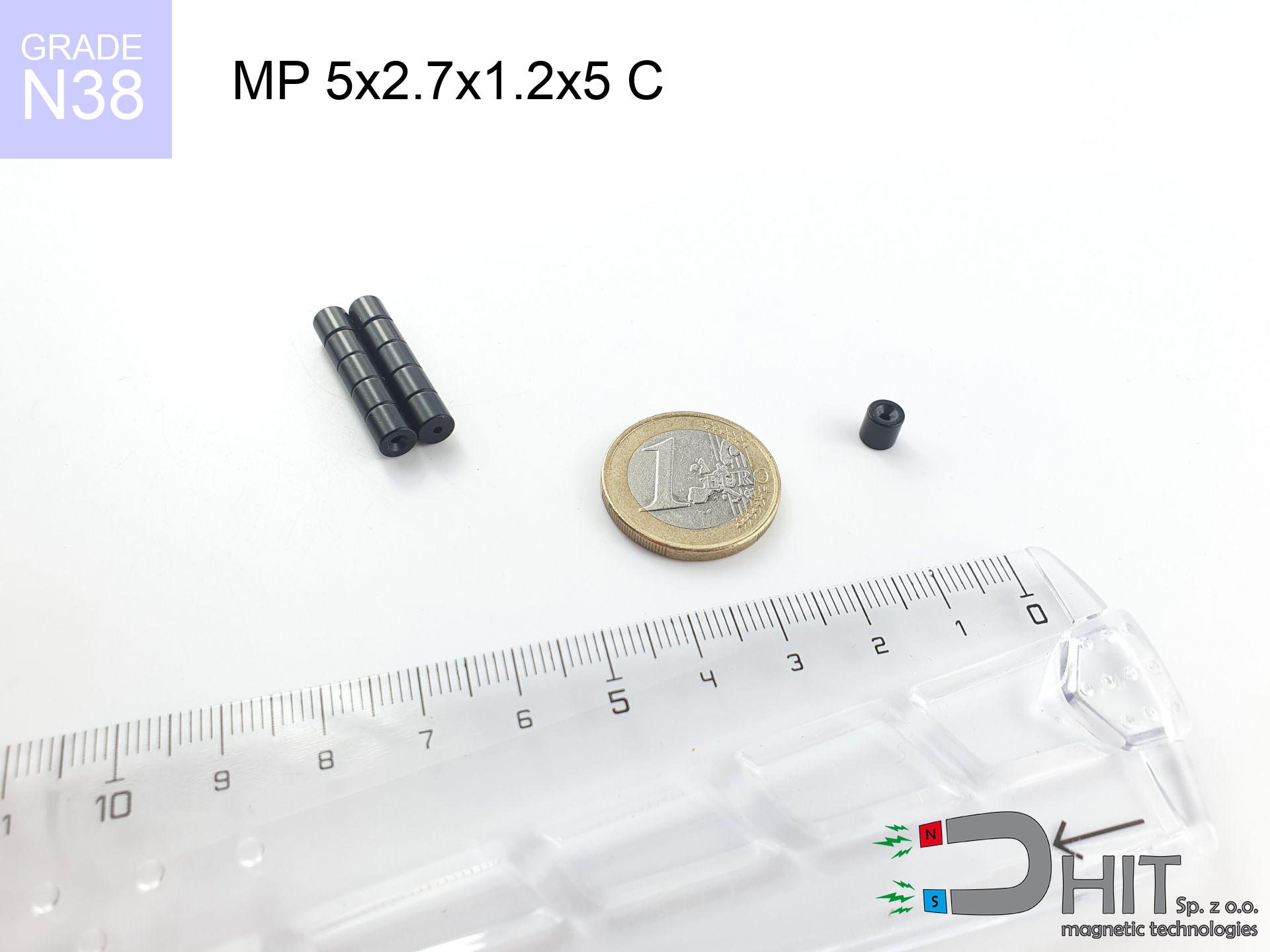
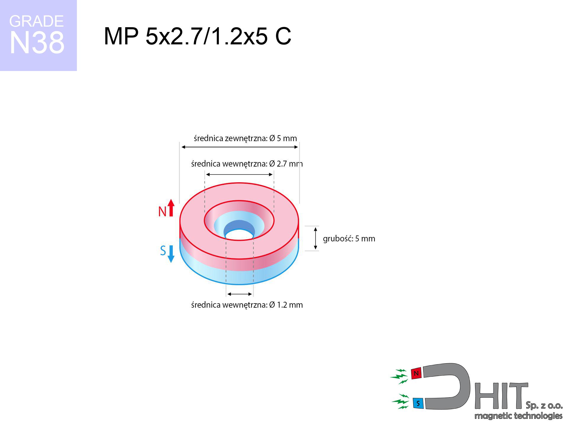
MP 5x2.7/1.2x5 C / N38 - ring magnet
ring magnet
Catalog no 030201
GTIN/EAN: 5906301812180
Diameter
5 mm [±0,1 mm]
internal diameter Ø
2.7/1.2 mm [±0,1 mm]
Height
5 mm [±0,1 mm]
Weight
0.69 g
Magnetization Direction
↑ axial
Load capacity
0.75 kg / 7.31 N
Magnetic Induction
553.14 mT / 5531 Gs
Coating
[NiCuNi] Nickel
0.836 ZŁ with VAT / pcs + price for transport
0.680 ZŁ net + 23% VAT / pcs
bulk discounts:
Need more?
Give us a call
+48 22 499 98 98
or let us know using
our online form
through our site.
Strength and structure of neodymium magnets can be calculated on our
force calculator.
Same-day shipping for orders placed before 14:00.
Technical parameters - MP 5x2.7/1.2x5 C / N38 - ring magnet
Specification / characteristics - MP 5x2.7/1.2x5 C / N38 - ring magnet
| properties | values |
|---|---|
| Cat. no. | 030201 |
| GTIN/EAN | 5906301812180 |
| Production/Distribution | Dhit sp. z o.o. |
| Country of origin | Poland / China / Germany |
| Customs code | 85059029 |
| Diameter | 5 mm [±0,1 mm] |
| internal diameter Ø | 2.7/1.2 mm [±0,1 mm] |
| Height | 5 mm [±0,1 mm] |
| Weight | 0.69 g |
| Magnetization Direction | ↑ axial |
| Load capacity ~ ? | 0.75 kg / 7.31 N |
| Magnetic Induction ~ ? | 553.14 mT / 5531 Gs |
| Coating | [NiCuNi] Nickel |
| Manufacturing Tolerance | ±0.1 mm |
Magnetic properties of material N38
| properties | values | units |
|---|---|---|
| remenance Br [min. - max.] ? | 12.2-12.6 | kGs |
| remenance Br [min. - max.] ? | 1220-1260 | mT |
| coercivity bHc ? | 10.8-11.5 | kOe |
| coercivity bHc ? | 860-915 | kA/m |
| actual internal force iHc | ≥ 12 | kOe |
| actual internal force iHc | ≥ 955 | kA/m |
| energy density [min. - max.] ? | 36-38 | BH max MGOe |
| energy density [min. - max.] ? | 287-303 | BH max KJ/m |
| max. temperature ? | ≤ 80 | °C |
Physical properties of sintered neodymium magnets Nd2Fe14B at 20°C
| properties | values | units |
|---|---|---|
| Vickers hardness | ≥550 | Hv |
| Density | ≥7.4 | g/cm3 |
| Curie Temperature TC | 312 - 380 | °C |
| Curie Temperature TF | 593 - 716 | °F |
| Specific resistance | 150 | μΩ⋅cm |
| Bending strength | 250 | MPa |
| Compressive strength | 1000~1100 | MPa |
| Thermal expansion parallel (∥) to orientation (M) | (3-4) x 10-6 | °C-1 |
| Thermal expansion perpendicular (⊥) to orientation (M) | -(1-3) x 10-6 | °C-1 |
| Young's modulus | 1.7 x 10⁴ | kg/mm² |
Engineering simulation of the assembly - report
Presented values constitute the outcome of a physical simulation. Results were calculated on algorithms for the material Nd2Fe14B. Actual conditions might slightly deviate from the simulation results. Use these data as a supplementary guide for designers.
Table 1: Static force (pull vs distance) - interaction chart
MP 5x2.7/1.2x5 C / N38
| Distance (mm) | Induction (Gauss) / mT | Pull Force (kg/lbs/g/N) | Risk Status |
|---|---|---|---|
| 0 mm |
5322 Gs
532.2 mT
|
0.75 kg / 1.65 LBS
750.0 g / 7.4 N
|
safe |
| 1 mm |
3295 Gs
329.5 mT
|
0.29 kg / 0.63 LBS
287.5 g / 2.8 N
|
safe |
| 2 mm |
1883 Gs
188.3 mT
|
0.09 kg / 0.21 LBS
93.9 g / 0.9 N
|
safe |
| 3 mm |
1098 Gs
109.8 mT
|
0.03 kg / 0.07 LBS
31.9 g / 0.3 N
|
safe |
| 5 mm |
440 Gs
44.0 mT
|
0.01 kg / 0.01 LBS
5.1 g / 0.1 N
|
safe |
| 10 mm |
92 Gs
9.2 mT
|
0.00 kg / 0.00 LBS
0.2 g / 0.0 N
|
safe |
| 15 mm |
33 Gs
3.3 mT
|
0.00 kg / 0.00 LBS
0.0 g / 0.0 N
|
safe |
| 20 mm |
15 Gs
1.5 mT
|
0.00 kg / 0.00 LBS
0.0 g / 0.0 N
|
safe |
| 30 mm |
5 Gs
0.5 mT
|
0.00 kg / 0.00 LBS
0.0 g / 0.0 N
|
safe |
| 50 mm |
1 Gs
0.1 mT
|
0.00 kg / 0.00 LBS
0.0 g / 0.0 N
|
safe |
Table 2: Vertical load (wall)
MP 5x2.7/1.2x5 C / N38
| Distance (mm) | Friction coefficient | Pull Force (kg/lbs/g/N) |
|---|---|---|
| 0 mm | Stal (~0.2) |
0.15 kg / 0.33 LBS
150.0 g / 1.5 N
|
| 1 mm | Stal (~0.2) |
0.06 kg / 0.13 LBS
58.0 g / 0.6 N
|
| 2 mm | Stal (~0.2) |
0.02 kg / 0.04 LBS
18.0 g / 0.2 N
|
| 3 mm | Stal (~0.2) |
0.01 kg / 0.01 LBS
6.0 g / 0.1 N
|
| 5 mm | Stal (~0.2) |
0.00 kg / 0.00 LBS
2.0 g / 0.0 N
|
| 10 mm | Stal (~0.2) |
0.00 kg / 0.00 LBS
0.0 g / 0.0 N
|
| 15 mm | Stal (~0.2) |
0.00 kg / 0.00 LBS
0.0 g / 0.0 N
|
| 20 mm | Stal (~0.2) |
0.00 kg / 0.00 LBS
0.0 g / 0.0 N
|
| 30 mm | Stal (~0.2) |
0.00 kg / 0.00 LBS
0.0 g / 0.0 N
|
| 50 mm | Stal (~0.2) |
0.00 kg / 0.00 LBS
0.0 g / 0.0 N
|
Table 3: Vertical assembly (shearing) - vertical pull
MP 5x2.7/1.2x5 C / N38
| Surface type | Friction coefficient / % Mocy | Max load (kg/lbs/g/N) |
|---|---|---|
| Raw steel |
µ = 0.3
30% Nominalnej Siły
|
0.22 kg / 0.50 LBS
225.0 g / 2.2 N
|
| Painted steel (standard) |
µ = 0.2
20% Nominalnej Siły
|
0.15 kg / 0.33 LBS
150.0 g / 1.5 N
|
| Oily/slippery steel |
µ = 0.1
10% Nominalnej Siły
|
0.08 kg / 0.17 LBS
75.0 g / 0.7 N
|
| Magnet with anti-slip rubber |
µ = 0.5
50% Nominalnej Siły
|
0.38 kg / 0.83 LBS
375.0 g / 3.7 N
|
Table 4: Steel thickness (substrate influence) - sheet metal selection
MP 5x2.7/1.2x5 C / N38
| Steel thickness (mm) | % power | Real pull force (kg/lbs/g/N) |
|---|---|---|
| 0.5 mm |
|
0.08 kg / 0.17 LBS
75.0 g / 0.7 N
|
| 1 mm |
|
0.19 kg / 0.41 LBS
187.5 g / 1.8 N
|
| 2 mm |
|
0.38 kg / 0.83 LBS
375.0 g / 3.7 N
|
| 3 mm |
|
0.56 kg / 1.24 LBS
562.5 g / 5.5 N
|
| 5 mm |
|
0.75 kg / 1.65 LBS
750.0 g / 7.4 N
|
| 10 mm |
|
0.75 kg / 1.65 LBS
750.0 g / 7.4 N
|
| 11 mm |
|
0.75 kg / 1.65 LBS
750.0 g / 7.4 N
|
| 12 mm |
|
0.75 kg / 1.65 LBS
750.0 g / 7.4 N
|
Table 5: Working in heat (stability) - thermal limit
MP 5x2.7/1.2x5 C / N38
| Ambient temp. (°C) | Power loss | Remaining pull (kg/lbs/g/N) | Status |
|---|---|---|---|
| 20 °C | 0.0% |
0.75 kg / 1.65 LBS
750.0 g / 7.4 N
|
OK |
| 40 °C | -2.2% |
0.73 kg / 1.62 LBS
733.5 g / 7.2 N
|
OK |
| 60 °C | -4.4% |
0.72 kg / 1.58 LBS
717.0 g / 7.0 N
|
OK |
| 80 °C | -6.6% |
0.70 kg / 1.54 LBS
700.5 g / 6.9 N
|
|
| 100 °C | -28.8% |
0.53 kg / 1.18 LBS
534.0 g / 5.2 N
|
Table 6: Magnet-Magnet interaction (attraction) - field range
MP 5x2.7/1.2x5 C / N38
| Gap (mm) | Attraction (kg/lbs) (N-S) | Lateral Force (kg/lbs/g/N) | Repulsion (kg/lbs) (N-N) |
|---|---|---|---|
| 0 mm |
2.75 kg / 6.06 LBS
5 924 Gs
|
0.41 kg / 0.91 LBS
412 g / 4.0 N
|
N/A |
| 1 mm |
1.77 kg / 3.90 LBS
8 541 Gs
|
0.27 kg / 0.58 LBS
265 g / 2.6 N
|
1.59 kg / 3.51 LBS
~0 Gs
|
| 2 mm |
1.05 kg / 2.32 LBS
6 590 Gs
|
0.16 kg / 0.35 LBS
158 g / 1.5 N
|
0.95 kg / 2.09 LBS
~0 Gs
|
| 3 mm |
0.60 kg / 1.33 LBS
4 992 Gs
|
0.09 kg / 0.20 LBS
91 g / 0.9 N
|
0.54 kg / 1.20 LBS
~0 Gs
|
| 5 mm |
0.20 kg / 0.44 LBS
2 860 Gs
|
0.03 kg / 0.07 LBS
30 g / 0.3 N
|
0.18 kg / 0.39 LBS
~0 Gs
|
| 10 mm |
0.02 kg / 0.04 LBS
880 Gs
|
0.00 kg / 0.01 LBS
3 g / 0.0 N
|
0.02 kg / 0.04 LBS
~0 Gs
|
| 20 mm |
0.00 kg / 0.00 LBS
184 Gs
|
0.00 kg / 0.00 LBS
0 g / 0.0 N
|
0.00 kg / 0.00 LBS
~0 Gs
|
| 50 mm |
0.00 kg / 0.00 LBS
16 Gs
|
0.00 kg / 0.00 LBS
0 g / 0.0 N
|
0.00 kg / 0.00 LBS
~0 Gs
|
| 60 mm |
0.00 kg / 0.00 LBS
10 Gs
|
0.00 kg / 0.00 LBS
0 g / 0.0 N
|
0.00 kg / 0.00 LBS
~0 Gs
|
| 70 mm |
0.00 kg / 0.00 LBS
6 Gs
|
0.00 kg / 0.00 LBS
0 g / 0.0 N
|
0.00 kg / 0.00 LBS
~0 Gs
|
| 80 mm |
0.00 kg / 0.00 LBS
4 Gs
|
0.00 kg / 0.00 LBS
0 g / 0.0 N
|
0.00 kg / 0.00 LBS
~0 Gs
|
| 90 mm |
0.00 kg / 0.00 LBS
3 Gs
|
0.00 kg / 0.00 LBS
0 g / 0.0 N
|
0.00 kg / 0.00 LBS
~0 Gs
|
| 100 mm |
0.00 kg / 0.00 LBS
2 Gs
|
0.00 kg / 0.00 LBS
0 g / 0.0 N
|
0.00 kg / 0.00 LBS
~0 Gs
|
Table 7: Hazards (electronics) - warnings
MP 5x2.7/1.2x5 C / N38
| Object / Device | Limit (Gauss) / mT | Safe distance |
|---|---|---|
| Pacemaker | 5 Gs (0.5 mT) | 3.0 cm |
| Hearing aid | 10 Gs (1.0 mT) | 2.5 cm |
| Mechanical watch | 20 Gs (2.0 mT) | 2.0 cm |
| Mobile device | 40 Gs (4.0 mT) | 1.5 cm |
| Car key | 50 Gs (5.0 mT) | 1.5 cm |
| Payment card | 400 Gs (40.0 mT) | 1.0 cm |
| HDD hard drive | 600 Gs (60.0 mT) | 0.5 cm |
Table 8: Collisions (cracking risk) - warning
MP 5x2.7/1.2x5 C / N38
| Start from (mm) | Speed (km/h) | Energy (J) | Predicted outcome |
|---|---|---|---|
| 10 mm |
33.26 km/h
(9.24 m/s)
|
0.03 J | |
| 30 mm |
57.59 km/h
(16.00 m/s)
|
0.09 J | |
| 50 mm |
74.35 km/h
(20.65 m/s)
|
0.15 J | |
| 100 mm |
105.14 km/h
(29.21 m/s)
|
0.29 J |
Table 9: Anti-corrosion coating durability
MP 5x2.7/1.2x5 C / N38
| Technical parameter | Value / Description |
|---|---|
| Coating type | [NiCuNi] Nickel |
| Layer structure | Nickel - Copper - Nickel |
| Layer thickness | 10-20 µm |
| Salt spray test (SST) ? | 24 h |
| Recommended environment | Indoors only (dry) |
Table 10: Electrical data (Flux)
MP 5x2.7/1.2x5 C / N38
| Parameter | Value | SI Unit / Description |
|---|---|---|
| Magnetic Flux | 862 Mx | 8.6 µWb |
| Pc Coefficient | 0.83 | High (Stable) |
Table 11: Physics of underwater searching
MP 5x2.7/1.2x5 C / N38
| Environment | Effective steel pull | Effect |
|---|---|---|
| Air (land) | 0.75 kg | Standard |
| Water (riverbed) |
0.86 kg
(+0.11 kg buoyancy gain)
|
+14.5% |
1. Shear force
*Warning: On a vertical wall, the magnet holds only approx. 20-30% of its max power.
2. Steel thickness impact
*Thin steel (e.g. computer case) significantly reduces the holding force.
3. Temperature resistance
*For standard magnets, the max working temp is 80°C.
4. Demagnetization curve and operating point (B-H)
chart generated for the permeance coefficient Pc (Permeance Coefficient) = 0.83
This simulation demonstrates the magnetic stability of the selected magnet under specific geometric conditions. The solid red line represents the demagnetization curve (material potential), while the dashed blue line is the load line based on the magnet's geometry. The Pc (Permeance Coefficient), also known as the load line slope, is a dimensionless value that describes the relationship between the magnet's shape and its magnetic stability. The intersection of these two lines (the black dot) is the operating point — it determines the actual magnetic flux density generated by the magnet in this specific configuration. A higher Pc value means the magnet is more 'slender' (tall relative to its area), resulting in a higher operating point and better resistance to irreversible demagnetization caused by external fields or temperature. A value of 0.42 is relatively low (typical for flat magnets), meaning the operating point is closer to the 'knee' of the curve — caution is advised when operating at temperatures near the maximum limit to avoid strength loss.
Material specification
| iron (Fe) | 64% – 68% |
| neodymium (Nd) | 29% – 32% |
| boron (B) | 1.1% – 1.2% |
| dysprosium (Dy) | 0.5% – 2.0% |
| coating (Ni-Cu-Ni) | < 0.05% |
Sustainability
| recyclability (EoL) | 100% |
| recycled raw materials | ~10% (pre-cons) |
| carbon footprint | low / zredukowany |
| waste code (EWC) | 16 02 16 |
See more products


Advantages and disadvantages of rare earth magnets.
Strengths
- Their power remains stable, and after around 10 years it decreases only by ~1% (according to research),
- Neodymium magnets are characterized by extremely resistant to magnetic field loss caused by magnetic disturbances,
- The use of an elegant coating of noble metals (nickel, gold, silver) causes the element to have aesthetics,
- Neodymium magnets achieve maximum magnetic induction on a contact point, which increases force concentration,
- Neodymium magnets are characterized by very high magnetic induction on the magnet surface and are able to act (depending on the shape) even at a temperature of 230°C or more...
- Thanks to versatility in forming and the capacity to customize to client solutions,
- Fundamental importance in innovative solutions – they are utilized in hard drives, motor assemblies, diagnostic systems, as well as other advanced devices.
- Relatively small size with high pulling force – neodymium magnets offer impressive pulling force in small dimensions, which allows their use in small systems
Weaknesses
- At very strong impacts they can crack, therefore we advise placing them in special holders. A metal housing provides additional protection against damage, as well as increases the magnet's durability.
- NdFeB magnets lose strength when exposed to high temperatures. After reaching 80°C, many of them experience permanent drop of power (a factor is the shape and dimensions of the magnet). We offer magnets specially adapted to work at temperatures up to 230°C marked [AH], which are extremely resistant to heat
- They rust in a humid environment. For use outdoors we suggest using waterproof magnets e.g. in rubber, plastic
- Due to limitations in realizing threads and complicated forms in magnets, we recommend using a housing - magnetic mechanism.
- Potential hazard related to microscopic parts of magnets can be dangerous, when accidentally swallowed, which is particularly important in the aspect of protecting the youngest. Additionally, small components of these magnets can complicate diagnosis medical when they are in the body.
- With mass production the cost of neodymium magnets can be a barrier,
Lifting parameters
Maximum lifting force for a neodymium magnet – what contributes to it?
- using a plate made of mild steel, acting as a magnetic yoke
- possessing a thickness of minimum 10 mm to avoid saturation
- with a surface free of scratches
- without the slightest insulating layer between the magnet and steel
- during pulling in a direction vertical to the plane
- at temperature approx. 20 degrees Celsius
Lifting capacity in real conditions – factors
- Space between surfaces – even a fraction of a millimeter of separation (caused e.g. by veneer or dirt) significantly weakens the pulling force, often by half at just 0.5 mm.
- Force direction – declared lifting capacity refers to detachment vertically. When applying parallel force, the magnet exhibits significantly lower power (typically approx. 20-30% of nominal force).
- Element thickness – for full efficiency, the steel must be adequately massive. Thin sheet restricts the attraction force (the magnet "punches through" it).
- Plate material – mild steel attracts best. Higher carbon content decrease magnetic properties and holding force.
- Plate texture – smooth surfaces guarantee perfect abutment, which increases field saturation. Rough surfaces reduce efficiency.
- Heat – NdFeB sinters have a sensitivity to temperature. At higher temperatures they lose power, and at low temperatures they can be stronger (up to a certain limit).
Lifting capacity testing was performed on plates with a smooth surface of optimal thickness, under a perpendicular pulling force, whereas under parallel forces the holding force is lower. Additionally, even a minimal clearance between the magnet and the plate lowers the holding force.
Warnings
Protective goggles
Watch out for shards. Magnets can fracture upon violent connection, ejecting shards into the air. Eye protection is mandatory.
ICD Warning
For implant holders: Strong magnetic fields affect electronics. Keep minimum 30 cm distance or request help to work with the magnets.
Precision electronics
GPS units and mobile phones are extremely susceptible to magnetism. Close proximity with a strong magnet can decalibrate the sensors in your phone.
Conscious usage
Use magnets with awareness. Their powerful strength can surprise even experienced users. Plan your moves and respect their power.
Magnetic media
Equipment safety: Strong magnets can damage data carriers and delicate electronics (heart implants, medical aids, timepieces).
Permanent damage
Monitor thermal conditions. Heating the magnet above 80 degrees Celsius will destroy its magnetic structure and pulling force.
Metal Allergy
Certain individuals suffer from a contact allergy to nickel, which is the common plating for neodymium magnets. Frequent touching can result in dermatitis. We recommend use protective gloves.
Serious injuries
Risk of injury: The attraction force is so immense that it can cause hematomas, crushing, and even bone fractures. Use thick gloves.
Danger to the youngest
Product intended for adults. Tiny parts pose a choking risk, causing serious injuries. Keep out of reach of children and animals.
Combustion hazard
Machining of NdFeB material carries a risk of fire hazard. Neodymium dust oxidizes rapidly with oxygen and is difficult to extinguish.
Tabela kosztu i czasu dostawy
Płatność przed wysyłką:

GLS kurier
Przesyłka będzie u Ciebie za 2-3 dni
14.99 ZŁ

InPost Paczkomaty 24/7
Przesyłka będzie u Ciebie za 1-2 dni
12.30 ZŁ
Płatność przy odbiorze (pobranie):
GLS kurier
Przesyłka będzie u Ciebie za 1-2 dni
23.00 ZŁ
Rate the product
Your rating