
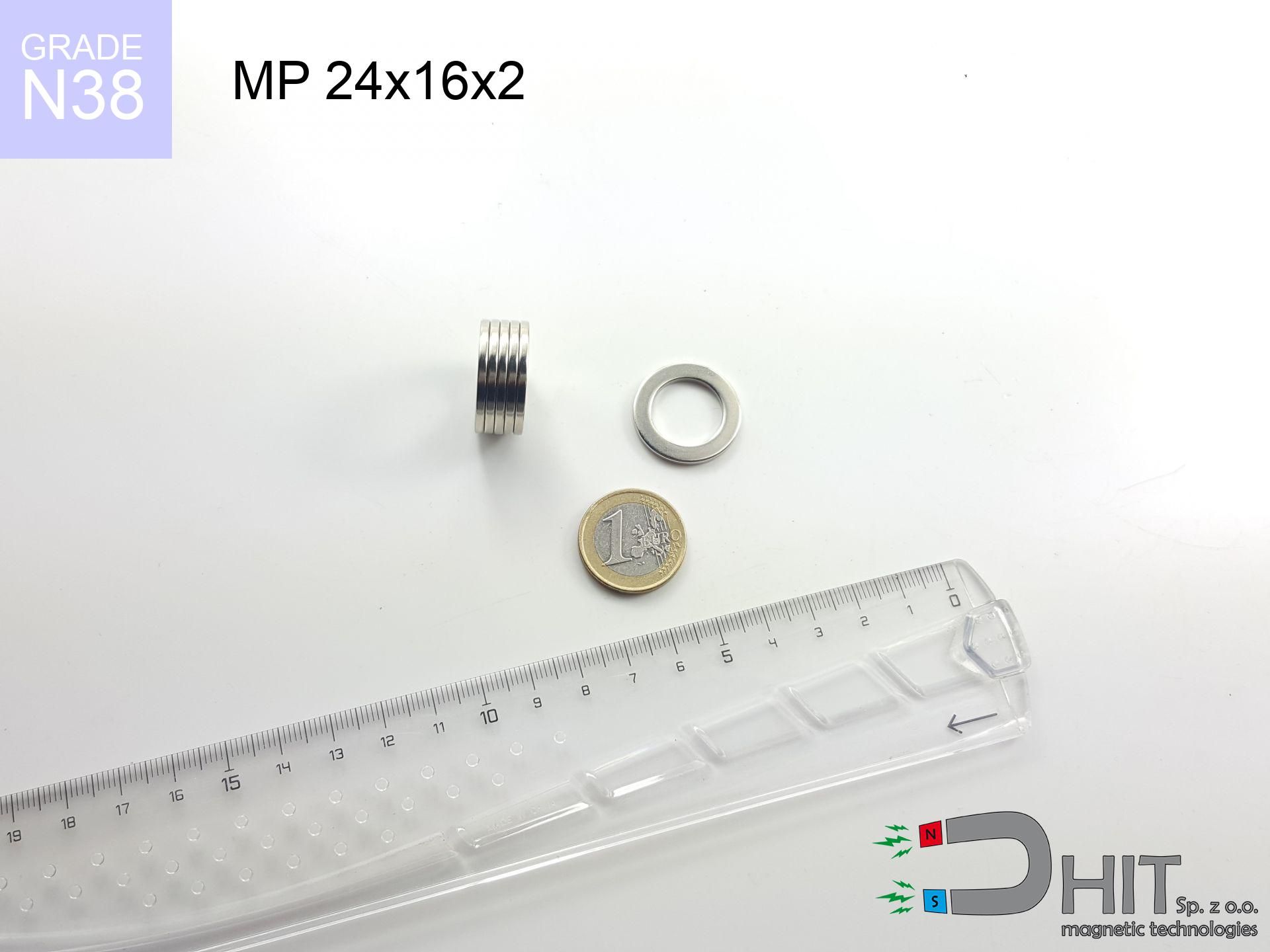
MP 24x16x2 / N38 - ring magnet
ring magnet
Catalog no 030495
GTIN/EAN: 5906301812364
Diameter
24 mm [±0,1 mm]
internal diameter Ø
16 mm [±0,1 mm]
Height
2 mm [±0,1 mm]
Weight
3.77 g
Magnetization Direction
↑ axial
Load capacity
0.94 kg / 9.22 N
Magnetic Induction
101.91 mT / 1019 Gs
Coating
[NiCuNi] Nickel
3.69 ZŁ with VAT / pcs + price for transport
3.00 ZŁ net + 23% VAT / pcs
bulk discounts:
Need more?
Call us now
+48 888 99 98 98
if you prefer send us a note by means of
inquiry form
our website.
Strength as well as structure of magnetic components can be checked using our
modular calculator.
Orders placed before 14:00 will be shipped the same business day.
Technical - MP 24x16x2 / N38 - ring magnet
Specification / characteristics - MP 24x16x2 / N38 - ring magnet
| properties | values |
|---|---|
| Cat. no. | 030495 |
| GTIN/EAN | 5906301812364 |
| Production/Distribution | Dhit sp. z o.o. |
| Country of origin | Poland / China / Germany |
| Customs code | 85059029 |
| Diameter | 24 mm [±0,1 mm] |
| internal diameter Ø | 16 mm [±0,1 mm] |
| Height | 2 mm [±0,1 mm] |
| Weight | 3.77 g |
| Magnetization Direction | ↑ axial |
| Load capacity ~ ? | 0.94 kg / 9.22 N |
| Magnetic Induction ~ ? | 101.91 mT / 1019 Gs |
| Coating | [NiCuNi] Nickel |
| Manufacturing Tolerance | ±0.1 mm |
Magnetic properties of material N38
| properties | values | units |
|---|---|---|
| remenance Br [min. - max.] ? | 12.2-12.6 | kGs |
| remenance Br [min. - max.] ? | 1220-1260 | mT |
| coercivity bHc ? | 10.8-11.5 | kOe |
| coercivity bHc ? | 860-915 | kA/m |
| actual internal force iHc | ≥ 12 | kOe |
| actual internal force iHc | ≥ 955 | kA/m |
| energy density [min. - max.] ? | 36-38 | BH max MGOe |
| energy density [min. - max.] ? | 287-303 | BH max KJ/m |
| max. temperature ? | ≤ 80 | °C |
Physical properties of sintered neodymium magnets Nd2Fe14B at 20°C
| properties | values | units |
|---|---|---|
| Vickers hardness | ≥550 | Hv |
| Density | ≥7.4 | g/cm3 |
| Curie Temperature TC | 312 - 380 | °C |
| Curie Temperature TF | 593 - 716 | °F |
| Specific resistance | 150 | μΩ⋅cm |
| Bending strength | 250 | MPa |
| Compressive strength | 1000~1100 | MPa |
| Thermal expansion parallel (∥) to orientation (M) | (3-4) x 10-6 | °C-1 |
| Thermal expansion perpendicular (⊥) to orientation (M) | -(1-3) x 10-6 | °C-1 |
| Young's modulus | 1.7 x 10⁴ | kg/mm² |
Engineering simulation of the magnet - data
Presented values constitute the result of a mathematical analysis. Results were calculated on models for the class Nd2Fe14B. Real-world performance may differ from theoretical values. Please consider these data as a reference point for designers.
Table 1: Static pull force (pull vs distance) - characteristics
MP 24x16x2 / N38
| Distance (mm) | Induction (Gauss) / mT | Pull Force (kg/lbs/g/N) | Risk Status |
|---|---|---|---|
| 0 mm |
5807 Gs
580.7 mT
|
0.94 kg / 2.07 lbs
940.0 g / 9.2 N
|
weak grip |
| 1 mm |
5318 Gs
531.8 mT
|
0.79 kg / 1.74 lbs
788.4 g / 7.7 N
|
weak grip |
| 2 mm |
4833 Gs
483.3 mT
|
0.65 kg / 1.44 lbs
651.1 g / 6.4 N
|
weak grip |
| 3 mm |
4366 Gs
436.6 mT
|
0.53 kg / 1.17 lbs
531.5 g / 5.2 N
|
weak grip |
| 5 mm |
3517 Gs
351.7 mT
|
0.34 kg / 0.76 lbs
344.9 g / 3.4 N
|
weak grip |
| 10 mm |
1995 Gs
199.5 mT
|
0.11 kg / 0.24 lbs
111.0 g / 1.1 N
|
weak grip |
| 15 mm |
1168 Gs
116.8 mT
|
0.04 kg / 0.08 lbs
38.0 g / 0.4 N
|
weak grip |
| 20 mm |
727 Gs
72.7 mT
|
0.01 kg / 0.03 lbs
14.7 g / 0.1 N
|
weak grip |
| 30 mm |
332 Gs
33.2 mT
|
0.00 kg / 0.01 lbs
3.1 g / 0.0 N
|
weak grip |
| 50 mm |
106 Gs
10.6 mT
|
0.00 kg / 0.00 lbs
0.3 g / 0.0 N
|
weak grip |
Table 2: Shear capacity (vertical surface)
MP 24x16x2 / N38
| Distance (mm) | Friction coefficient | Pull Force (kg/lbs/g/N) |
|---|---|---|
| 0 mm | Stal (~0.2) |
0.19 kg / 0.41 lbs
188.0 g / 1.8 N
|
| 1 mm | Stal (~0.2) |
0.16 kg / 0.35 lbs
158.0 g / 1.5 N
|
| 2 mm | Stal (~0.2) |
0.13 kg / 0.29 lbs
130.0 g / 1.3 N
|
| 3 mm | Stal (~0.2) |
0.11 kg / 0.23 lbs
106.0 g / 1.0 N
|
| 5 mm | Stal (~0.2) |
0.07 kg / 0.15 lbs
68.0 g / 0.7 N
|
| 10 mm | Stal (~0.2) |
0.02 kg / 0.05 lbs
22.0 g / 0.2 N
|
| 15 mm | Stal (~0.2) |
0.01 kg / 0.02 lbs
8.0 g / 0.1 N
|
| 20 mm | Stal (~0.2) |
0.00 kg / 0.00 lbs
2.0 g / 0.0 N
|
| 30 mm | Stal (~0.2) |
0.00 kg / 0.00 lbs
0.0 g / 0.0 N
|
| 50 mm | Stal (~0.2) |
0.00 kg / 0.00 lbs
0.0 g / 0.0 N
|
Table 3: Wall mounting (sliding) - vertical pull
MP 24x16x2 / N38
| Surface type | Friction coefficient / % Mocy | Max load (kg/lbs/g/N) |
|---|---|---|
| Raw steel |
µ = 0.3
30% Nominalnej Siły
|
0.28 kg / 0.62 lbs
282.0 g / 2.8 N
|
| Painted steel (standard) |
µ = 0.2
20% Nominalnej Siły
|
0.19 kg / 0.41 lbs
188.0 g / 1.8 N
|
| Oily/slippery steel |
µ = 0.1
10% Nominalnej Siły
|
0.09 kg / 0.21 lbs
94.0 g / 0.9 N
|
| Magnet with anti-slip rubber |
µ = 0.5
50% Nominalnej Siły
|
0.47 kg / 1.04 lbs
470.0 g / 4.6 N
|
Table 4: Steel thickness (substrate influence) - power losses
MP 24x16x2 / N38
| Steel thickness (mm) | % power | Real pull force (kg/lbs/g/N) |
|---|---|---|
| 0.5 mm |
|
0.09 kg / 0.21 lbs
94.0 g / 0.9 N
|
| 1 mm |
|
0.24 kg / 0.52 lbs
235.0 g / 2.3 N
|
| 2 mm |
|
0.47 kg / 1.04 lbs
470.0 g / 4.6 N
|
| 3 mm |
|
0.71 kg / 1.55 lbs
705.0 g / 6.9 N
|
| 5 mm |
|
0.94 kg / 2.07 lbs
940.0 g / 9.2 N
|
| 10 mm |
|
0.94 kg / 2.07 lbs
940.0 g / 9.2 N
|
| 11 mm |
|
0.94 kg / 2.07 lbs
940.0 g / 9.2 N
|
| 12 mm |
|
0.94 kg / 2.07 lbs
940.0 g / 9.2 N
|
Table 5: Thermal stability (material behavior) - resistance threshold
MP 24x16x2 / N38
| Ambient temp. (°C) | Power loss | Remaining pull (kg/lbs/g/N) | Status |
|---|---|---|---|
| 20 °C | 0.0% |
0.94 kg / 2.07 lbs
940.0 g / 9.2 N
|
OK |
| 40 °C | -2.2% |
0.92 kg / 2.03 lbs
919.3 g / 9.0 N
|
OK |
| 60 °C | -4.4% |
0.90 kg / 1.98 lbs
898.6 g / 8.8 N
|
OK |
| 80 °C | -6.6% |
0.88 kg / 1.94 lbs
878.0 g / 8.6 N
|
|
| 100 °C | -28.8% |
0.67 kg / 1.48 lbs
669.3 g / 6.6 N
|
Table 6: Two magnets (repulsion) - forces in the system
MP 24x16x2 / N38
| Gap (mm) | Attraction (kg/lbs) (N-S) | Shear Strength (kg/lbs/g/N) | Repulsion (kg/lbs) (N-N) |
|---|---|---|---|
| 0 mm |
79.38 kg / 175.01 lbs
6 091 Gs
|
11.91 kg / 26.25 lbs
11908 g / 116.8 N
|
N/A |
| 1 mm |
72.89 kg / 160.70 lbs
11 129 Gs
|
10.93 kg / 24.11 lbs
10934 g / 107.3 N
|
65.60 kg / 144.63 lbs
~0 Gs
|
| 2 mm |
66.58 kg / 146.78 lbs
10 636 Gs
|
9.99 kg / 22.02 lbs
9987 g / 98.0 N
|
59.92 kg / 132.10 lbs
~0 Gs
|
| 3 mm |
60.60 kg / 133.60 lbs
10 147 Gs
|
9.09 kg / 20.04 lbs
9090 g / 89.2 N
|
54.54 kg / 120.24 lbs
~0 Gs
|
| 5 mm |
49.75 kg / 109.67 lbs
9 194 Gs
|
7.46 kg / 16.45 lbs
7462 g / 73.2 N
|
44.77 kg / 98.70 lbs
~0 Gs
|
| 10 mm |
29.13 kg / 64.21 lbs
7 035 Gs
|
4.37 kg / 9.63 lbs
4369 g / 42.9 N
|
26.21 kg / 57.79 lbs
~0 Gs
|
| 20 mm |
9.37 kg / 20.67 lbs
3 991 Gs
|
1.41 kg / 3.10 lbs
1406 g / 13.8 N
|
8.44 kg / 18.60 lbs
~0 Gs
|
| 50 mm |
0.54 kg / 1.19 lbs
958 Gs
|
0.08 kg / 0.18 lbs
81 g / 0.8 N
|
0.49 kg / 1.07 lbs
~0 Gs
|
| 60 mm |
0.26 kg / 0.57 lbs
663 Gs
|
0.04 kg / 0.09 lbs
39 g / 0.4 N
|
0.23 kg / 0.51 lbs
~0 Gs
|
| 70 mm |
0.13 kg / 0.30 lbs
478 Gs
|
0.02 kg / 0.04 lbs
20 g / 0.2 N
|
0.12 kg / 0.27 lbs
~0 Gs
|
| 80 mm |
0.07 kg / 0.16 lbs
356 Gs
|
0.01 kg / 0.02 lbs
11 g / 0.1 N
|
0.07 kg / 0.15 lbs
~0 Gs
|
| 90 mm |
0.04 kg / 0.10 lbs
272 Gs
|
0.01 kg / 0.01 lbs
7 g / 0.1 N
|
0.04 kg / 0.09 lbs
~0 Gs
|
| 100 mm |
0.03 kg / 0.06 lbs
213 Gs
|
0.00 kg / 0.01 lbs
4 g / 0.0 N
|
0.02 kg / 0.05 lbs
~0 Gs
|
Table 7: Protective zones (implants) - precautionary measures
MP 24x16x2 / N38
| Object / Device | Limit (Gauss) / mT | Safe distance |
|---|---|---|
| Pacemaker | 5 Gs (0.5 mT) | 16.5 cm |
| Hearing aid | 10 Gs (1.0 mT) | 13.0 cm |
| Mechanical watch | 20 Gs (2.0 mT) | 10.0 cm |
| Mobile device | 40 Gs (4.0 mT) | 7.5 cm |
| Remote | 50 Gs (5.0 mT) | 7.0 cm |
| Payment card | 400 Gs (40.0 mT) | 3.0 cm |
| HDD hard drive | 600 Gs (60.0 mT) | 2.5 cm |
Table 8: Collisions (cracking risk) - collision effects
MP 24x16x2 / N38
| Start from (mm) | Speed (km/h) | Energy (J) | Predicted outcome |
|---|---|---|---|
| 10 mm |
17.06 km/h
(4.74 m/s)
|
0.04 J | |
| 30 mm |
27.64 km/h
(7.68 m/s)
|
0.11 J | |
| 50 mm |
35.62 km/h
(9.89 m/s)
|
0.18 J | |
| 100 mm |
50.36 km/h
(13.99 m/s)
|
0.37 J |
Table 9: Surface protection spec
MP 24x16x2 / N38
| Technical parameter | Value / Description |
|---|---|
| Coating type | [NiCuNi] Nickel |
| Layer structure | Nickel - Copper - Nickel |
| Layer thickness | 10-20 µm |
| Salt spray test (SST) ? | 24 h |
| Recommended environment | Indoors only (dry) |
Table 10: Electrical data (Pc)
MP 24x16x2 / N38
| Parameter | Value | SI Unit / Description |
|---|---|---|
| Magnetic Flux | 23 520 Mx | 235.2 µWb |
| Pc Coefficient | 1.04 | High (Stable) |
Table 11: Hydrostatics and buoyancy
MP 24x16x2 / N38
| Environment | Effective steel pull | Effect |
|---|---|---|
| Air (land) | 0.94 kg | Standard |
| Water (riverbed) |
1.08 kg
(+0.14 kg buoyancy gain)
|
+14.5% |
1. Vertical hold
*Caution: On a vertical surface, the magnet retains merely ~20% of its nominal pull.
2. Plate thickness effect
*Thin steel (e.g. computer case) severely reduces the holding force.
3. Heat tolerance
*For standard magnets, the critical limit is 80°C.
4. Demagnetization curve and operating point (B-H)
chart generated for the permeance coefficient Pc (Permeance Coefficient) = 1.04
The chart above illustrates the magnetic characteristics of the material within the second quadrant of the hysteresis loop. The solid red line represents the demagnetization curve (material potential), while the dashed blue line is the load line based on the magnet's geometry. The Pc (Permeance Coefficient), also known as the load line slope, is a dimensionless value that describes the relationship between the magnet's shape and its magnetic stability. The intersection of these two lines (the black dot) is the operating point — it determines the actual magnetic flux density generated by the magnet in this specific configuration. A higher Pc value means the magnet is more 'slender' (tall relative to its area), resulting in a higher operating point and better resistance to irreversible demagnetization caused by external fields or temperature. A value of 0.42 is relatively low (typical for flat magnets), meaning the operating point is closer to the 'knee' of the curve — caution is advised when operating at temperatures near the maximum limit to avoid strength loss.
Elemental analysis
| iron (Fe) | 64% – 68% |
| neodymium (Nd) | 29% – 32% |
| boron (B) | 1.1% – 1.2% |
| dysprosium (Dy) | 0.5% – 2.0% |
| coating (Ni-Cu-Ni) | < 0.05% |
Sustainability
| recyclability (EoL) | 100% |
| recycled raw materials | ~10% (pre-cons) |
| carbon footprint | low / zredukowany |
| waste code (EWC) | 16 02 16 |
View more proposals
![SM 25x200 [2xM8] / N42 - magnetic separator](https://cdn3.dhit.pl/graphics/products/sm-25x200-2xm8-dos.jpg "SM 25x200 [2xM8] / N42 - magnetic separator")
![SM 25x325 [2xM8] / N42 - magnetic separator](https://cdn3.dhit.pl/graphics/products/sm-25x325-2xm8-man.jpg "SM 25x325 [2xM8] / N42 - magnetic separator")


Strengths as well as weaknesses of Nd2Fe14B magnets.
Pros
- Their power remains stable, and after around 10 years it decreases only by ~1% (theoretically),
- Neodymium magnets are distinguished by extremely resistant to magnetic field loss caused by external field sources,
- By using a decorative layer of silver, the element has an professional look,
- Magnets are distinguished by impressive magnetic induction on the active area,
- Neodymium magnets are characterized by extremely high magnetic induction on the magnet surface and can work (depending on the shape) even at a temperature of 230°C or more...
- Thanks to versatility in forming and the ability to customize to complex applications,
- Fundamental importance in modern technologies – they serve a role in mass storage devices, electric motors, diagnostic systems, also industrial machines.
- Compactness – despite small sizes they generate large force, making them ideal for precision applications
Disadvantages
- They are prone to damage upon too strong impacts. To avoid cracks, it is worth securing magnets in special housings. Such protection not only protects the magnet but also increases its resistance to damage
- When exposed to high temperature, neodymium magnets experience a drop in force. Often, when the temperature exceeds 80°C, their power decreases (depending on the size and shape of the magnet). For those who need magnets for extreme conditions, we offer [AH] versions withstanding up to 230°C
- They oxidize in a humid environment - during use outdoors we suggest using waterproof magnets e.g. in rubber, plastic
- We suggest a housing - magnetic holder, due to difficulties in realizing nuts inside the magnet and complex forms.
- Health risk resulting from small fragments of magnets pose a threat, in case of ingestion, which becomes key in the aspect of protecting the youngest. Additionally, small elements of these products are able to be problematic in diagnostics medical when they are in the body.
- Due to neodymium price, their price is higher than average,
Pull force analysis
Best holding force of the magnet in ideal parameters – what it depends on?
- with the contact of a sheet made of low-carbon steel, guaranteeing full magnetic saturation
- whose thickness is min. 10 mm
- with an ground contact surface
- without any air gap between the magnet and steel
- under vertical application of breakaway force (90-degree angle)
- at conditions approx. 20°C
Determinants of lifting force in real conditions
- Space between magnet and steel – even a fraction of a millimeter of separation (caused e.g. by varnish or dirt) diminishes the magnet efficiency, often by half at just 0.5 mm.
- Angle of force application – highest force is obtained only during pulling at a 90° angle. The resistance to sliding of the magnet along the surface is standardly several times lower (approx. 1/5 of the lifting capacity).
- Wall thickness – thin material does not allow full use of the magnet. Part of the magnetic field passes through the material instead of generating force.
- Steel type – mild steel gives the best results. Alloy steels decrease magnetic properties and holding force.
- Surface quality – the more even the plate, the larger the contact zone and higher the lifting capacity. Unevenness creates an air distance.
- Thermal environment – temperature increase causes a temporary drop of force. It is worth remembering the maximum operating temperature for a given model.
Lifting capacity testing was carried out on plates with a smooth surface of optimal thickness, under a perpendicular pulling force, however under parallel forces the holding force is lower. Additionally, even a small distance between the magnet and the plate decreases the lifting capacity.
H&S for magnets
Protective goggles
Despite the nickel coating, neodymium is brittle and not impact-resistant. Avoid impacts, as the magnet may shatter into hazardous fragments.
Caution required
Handle with care. Neodymium magnets act from a long distance and snap with huge force, often faster than you can react.
Product not for children
Adult use only. Tiny parts pose a choking risk, leading to serious injuries. Keep away from children and animals.
Fire warning
Mechanical processing of neodymium magnets poses a fire hazard. Neodymium dust reacts violently with oxygen and is difficult to extinguish.
Warning for allergy sufferers
Some people experience a sensitization to nickel, which is the standard coating for NdFeB magnets. Extended handling might lead to skin redness. It is best to wear safety gloves.
Magnetic media
Very strong magnetic fields can erase data on credit cards, HDDs, and storage devices. Keep a distance of at least 10 cm.
Crushing force
Mind your fingers. Two powerful magnets will snap together immediately with a force of massive weight, crushing everything in their path. Be careful!
Life threat
Warning for patients: Powerful magnets affect electronics. Keep minimum 30 cm distance or request help to handle the magnets.
Thermal limits
Keep cool. Neodymium magnets are susceptible to heat. If you require resistance above 80°C, inquire about HT versions (H, SH, UH).
Threat to navigation
Remember: neodymium magnets generate a field that interferes with precision electronics. Keep a separation from your phone, tablet, and GPS.
Tabela kosztu i czasu dostawy
Płatność przed wysyłką:

GLS kurier
Przesyłka będzie u Ciebie za 2-3 dni
14.99 ZŁ

InPost Paczkomaty 24/7
Przesyłka będzie u Ciebie za 1-2 dni
12.30 ZŁ
Płatność przy odbiorze (pobranie):
GLS kurier
Przesyłka będzie u Ciebie za 1-2 dni
23.00 ZŁ
Rate the product
Your rating