
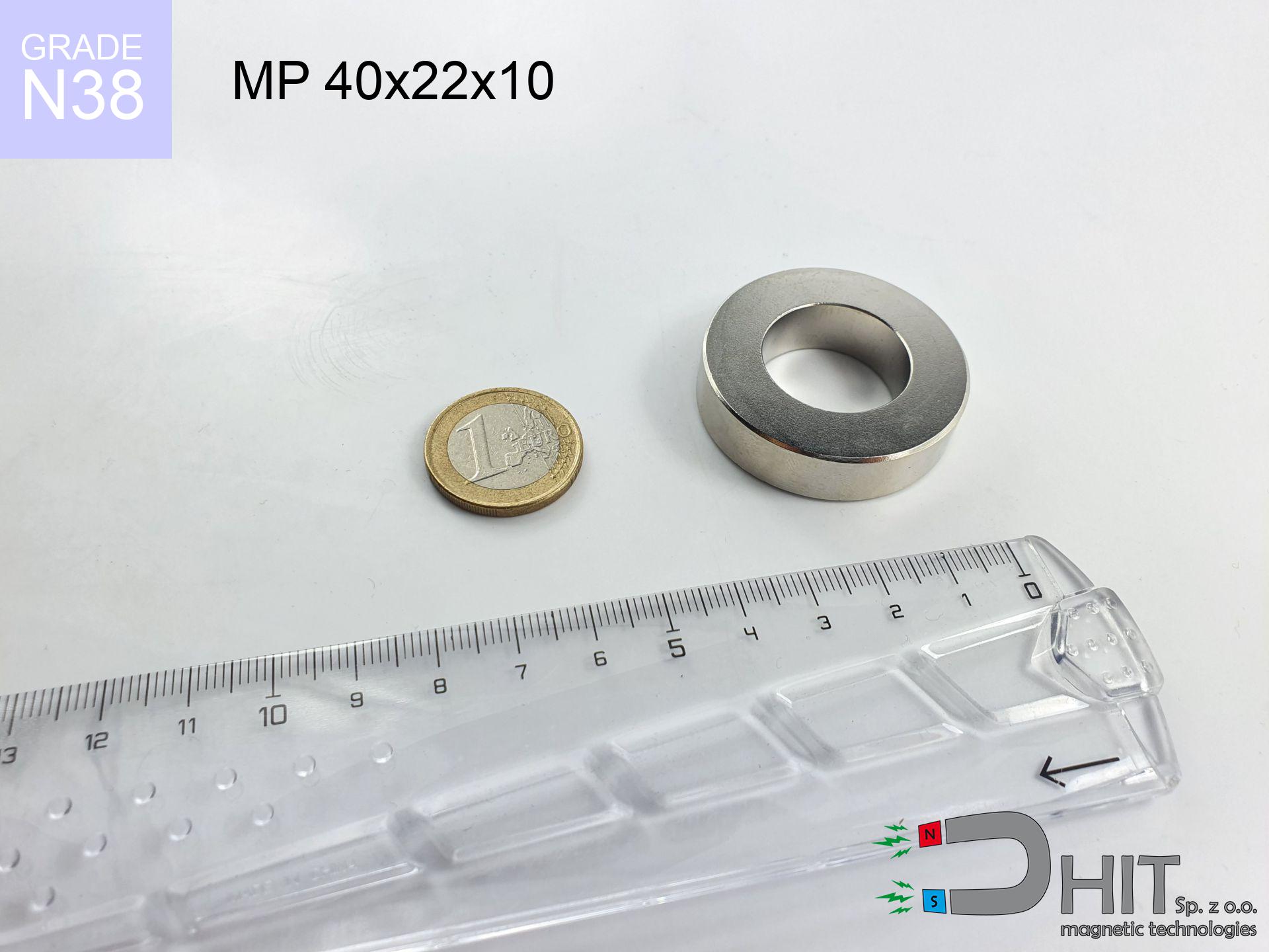
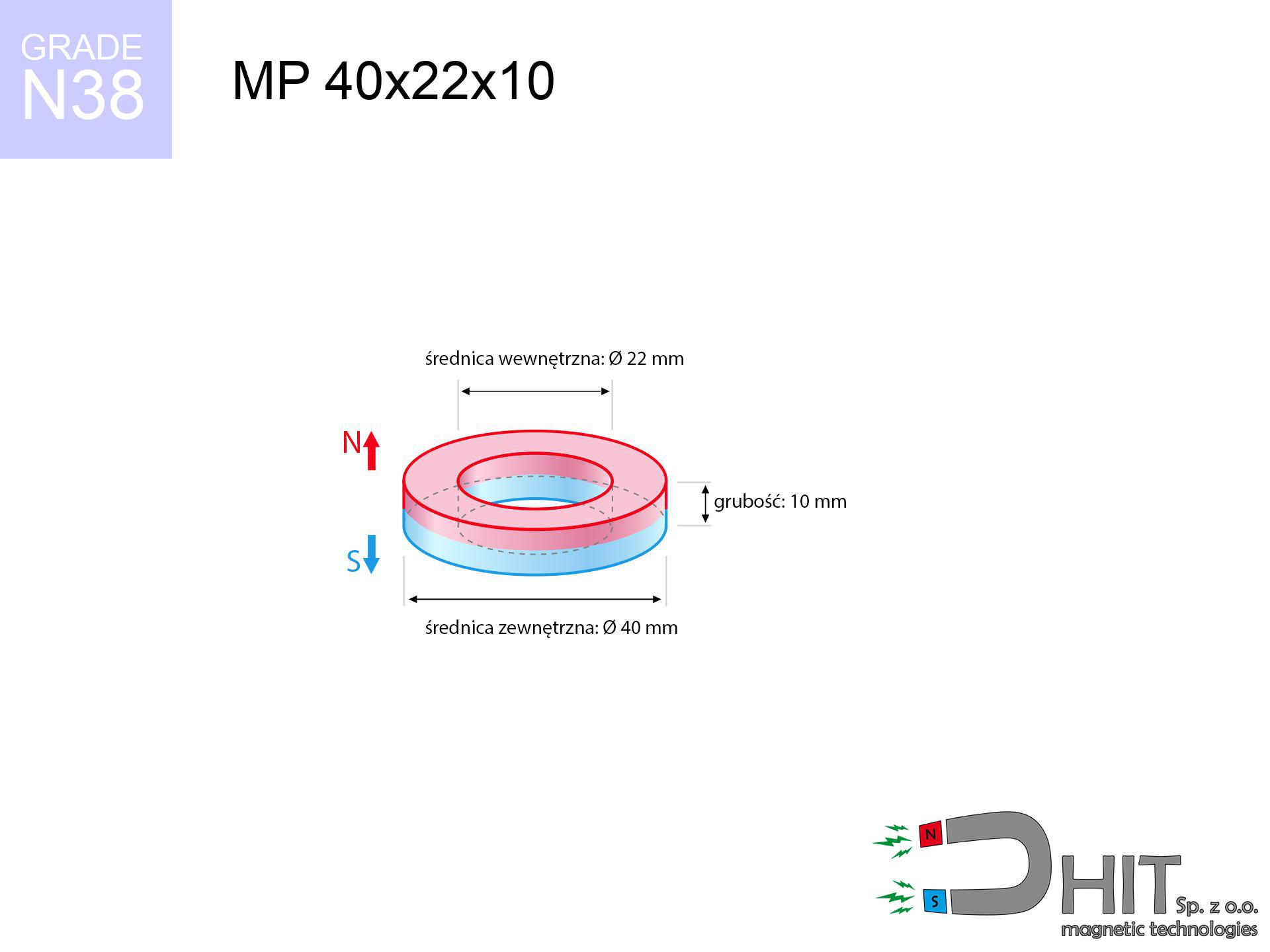
MP 40x22x10 / N38 - ring magnet
ring magnet
Catalog no 030344
GTIN/EAN: 5906301812296
Diameter
40 mm [±0,1 mm]
internal diameter Ø
22 mm [±0,1 mm]
Height
10 mm [±0,1 mm]
Weight
65.74 g
Magnetization Direction
↑ axial
Load capacity
19.34 kg / 189.71 N
Magnetic Induction
277.22 mT / 2772 Gs
Coating
[NiCuNi] Nickel
40.59 ZŁ with VAT / pcs + price for transport
33.00 ZŁ net + 23% VAT / pcs
bulk discounts:
Need more?
Give us a call
+48 22 499 98 98
otherwise send us a note via
form
through our site.
Parameters along with appearance of a magnet can be verified with our
modular calculator.
Same-day processing for orders placed before 14:00.
Detailed specification - MP 40x22x10 / N38 - ring magnet
Specification / characteristics - MP 40x22x10 / N38 - ring magnet
| properties | values |
|---|---|
| Cat. no. | 030344 |
| GTIN/EAN | 5906301812296 |
| Production/Distribution | Dhit sp. z o.o. |
| Country of origin | Poland / China / Germany |
| Customs code | 85059029 |
| Diameter | 40 mm [±0,1 mm] |
| internal diameter Ø | 22 mm [±0,1 mm] |
| Height | 10 mm [±0,1 mm] |
| Weight | 65.74 g |
| Magnetization Direction | ↑ axial |
| Load capacity ~ ? | 19.34 kg / 189.71 N |
| Magnetic Induction ~ ? | 277.22 mT / 2772 Gs |
| Coating | [NiCuNi] Nickel |
| Manufacturing Tolerance | ±0.1 mm |
Magnetic properties of material N38
| properties | values | units |
|---|---|---|
| remenance Br [min. - max.] ? | 12.2-12.6 | kGs |
| remenance Br [min. - max.] ? | 1220-1260 | mT |
| coercivity bHc ? | 10.8-11.5 | kOe |
| coercivity bHc ? | 860-915 | kA/m |
| actual internal force iHc | ≥ 12 | kOe |
| actual internal force iHc | ≥ 955 | kA/m |
| energy density [min. - max.] ? | 36-38 | BH max MGOe |
| energy density [min. - max.] ? | 287-303 | BH max KJ/m |
| max. temperature ? | ≤ 80 | °C |
Physical properties of sintered neodymium magnets Nd2Fe14B at 20°C
| properties | values | units |
|---|---|---|
| Vickers hardness | ≥550 | Hv |
| Density | ≥7.4 | g/cm3 |
| Curie Temperature TC | 312 - 380 | °C |
| Curie Temperature TF | 593 - 716 | °F |
| Specific resistance | 150 | μΩ⋅cm |
| Bending strength | 250 | MPa |
| Compressive strength | 1000~1100 | MPa |
| Thermal expansion parallel (∥) to orientation (M) | (3-4) x 10-6 | °C-1 |
| Thermal expansion perpendicular (⊥) to orientation (M) | -(1-3) x 10-6 | °C-1 |
| Young's modulus | 1.7 x 10⁴ | kg/mm² |
Technical modeling of the product - data
These information represent the direct effect of a engineering analysis. Values were calculated on algorithms for the class Nd2Fe14B. Actual conditions might slightly differ. Use these data as a reference point for designers.
Table 1: Static pull force (pull vs distance) - interaction chart
MP 40x22x10 / N38
| Distance (mm) | Induction (Gauss) / mT | Pull Force (kg/lbs/g/N) | Risk Status |
|---|---|---|---|
| 0 mm |
5269 Gs
526.9 mT
|
19.34 kg / 42.64 LBS
19340.0 g / 189.7 N
|
crushing |
| 1 mm |
5005 Gs
500.5 mT
|
17.46 kg / 38.48 LBS
17455.9 g / 171.2 N
|
crushing |
| 2 mm |
4739 Gs
473.9 mT
|
15.65 kg / 34.50 LBS
15647.5 g / 153.5 N
|
crushing |
| 3 mm |
4475 Gs
447.5 mT
|
13.95 kg / 30.75 LBS
13950.0 g / 136.8 N
|
crushing |
| 5 mm |
3960 Gs
396.0 mT
|
10.93 kg / 24.09 LBS
10927.7 g / 107.2 N
|
crushing |
| 10 mm |
2832 Gs
283.2 mT
|
5.59 kg / 12.32 LBS
5589.2 g / 54.8 N
|
warning |
| 15 mm |
1990 Gs
199.0 mT
|
2.76 kg / 6.09 LBS
2760.5 g / 27.1 N
|
warning |
| 20 mm |
1407 Gs
140.7 mT
|
1.38 kg / 3.04 LBS
1379.2 g / 13.5 N
|
weak grip |
| 30 mm |
745 Gs
74.5 mT
|
0.39 kg / 0.85 LBS
386.2 g / 3.8 N
|
weak grip |
| 50 mm |
268 Gs
26.8 mT
|
0.05 kg / 0.11 LBS
50.1 g / 0.5 N
|
weak grip |
Table 2: Shear load (vertical surface)
MP 40x22x10 / N38
| Distance (mm) | Friction coefficient | Pull Force (kg/lbs/g/N) |
|---|---|---|
| 0 mm | Stal (~0.2) |
3.87 kg / 8.53 LBS
3868.0 g / 37.9 N
|
| 1 mm | Stal (~0.2) |
3.49 kg / 7.70 LBS
3492.0 g / 34.3 N
|
| 2 mm | Stal (~0.2) |
3.13 kg / 6.90 LBS
3130.0 g / 30.7 N
|
| 3 mm | Stal (~0.2) |
2.79 kg / 6.15 LBS
2790.0 g / 27.4 N
|
| 5 mm | Stal (~0.2) |
2.19 kg / 4.82 LBS
2186.0 g / 21.4 N
|
| 10 mm | Stal (~0.2) |
1.12 kg / 2.46 LBS
1118.0 g / 11.0 N
|
| 15 mm | Stal (~0.2) |
0.55 kg / 1.22 LBS
552.0 g / 5.4 N
|
| 20 mm | Stal (~0.2) |
0.28 kg / 0.61 LBS
276.0 g / 2.7 N
|
| 30 mm | Stal (~0.2) |
0.08 kg / 0.17 LBS
78.0 g / 0.8 N
|
| 50 mm | Stal (~0.2) |
0.01 kg / 0.02 LBS
10.0 g / 0.1 N
|
Table 3: Vertical assembly (sliding) - vertical pull
MP 40x22x10 / N38
| Surface type | Friction coefficient / % Mocy | Max load (kg/lbs/g/N) |
|---|---|---|
| Raw steel |
µ = 0.3
30% Nominalnej Siły
|
5.80 kg / 12.79 LBS
5802.0 g / 56.9 N
|
| Painted steel (standard) |
µ = 0.2
20% Nominalnej Siły
|
3.87 kg / 8.53 LBS
3868.0 g / 37.9 N
|
| Oily/slippery steel |
µ = 0.1
10% Nominalnej Siły
|
1.93 kg / 4.26 LBS
1934.0 g / 19.0 N
|
| Magnet with anti-slip rubber |
µ = 0.5
50% Nominalnej Siły
|
9.67 kg / 21.32 LBS
9670.0 g / 94.9 N
|
Table 4: Steel thickness (substrate influence) - power losses
MP 40x22x10 / N38
| Steel thickness (mm) | % power | Real pull force (kg/lbs/g/N) |
|---|---|---|
| 0.5 mm |
|
0.97 kg / 2.13 LBS
967.0 g / 9.5 N
|
| 1 mm |
|
2.42 kg / 5.33 LBS
2417.5 g / 23.7 N
|
| 2 mm |
|
4.84 kg / 10.66 LBS
4835.0 g / 47.4 N
|
| 3 mm |
|
7.25 kg / 15.99 LBS
7252.5 g / 71.1 N
|
| 5 mm |
|
12.09 kg / 26.65 LBS
12087.5 g / 118.6 N
|
| 10 mm |
|
19.34 kg / 42.64 LBS
19340.0 g / 189.7 N
|
| 11 mm |
|
19.34 kg / 42.64 LBS
19340.0 g / 189.7 N
|
| 12 mm |
|
19.34 kg / 42.64 LBS
19340.0 g / 189.7 N
|
Table 5: Thermal stability (material behavior) - resistance threshold
MP 40x22x10 / N38
| Ambient temp. (°C) | Power loss | Remaining pull (kg/lbs/g/N) | Status |
|---|---|---|---|
| 20 °C | 0.0% |
19.34 kg / 42.64 LBS
19340.0 g / 189.7 N
|
OK |
| 40 °C | -2.2% |
18.91 kg / 41.70 LBS
18914.5 g / 185.6 N
|
OK |
| 60 °C | -4.4% |
18.49 kg / 40.76 LBS
18489.0 g / 181.4 N
|
OK |
| 80 °C | -6.6% |
18.06 kg / 39.82 LBS
18063.6 g / 177.2 N
|
|
| 100 °C | -28.8% |
13.77 kg / 30.36 LBS
13770.1 g / 135.1 N
|
Table 6: Two magnets (repulsion) - forces in the system
MP 40x22x10 / N38
| Gap (mm) | Attraction (kg/lbs) (N-S) | Sliding Force (kg/lbs/g/N) | Repulsion (kg/lbs) (N-N) |
|---|---|---|---|
| 0 mm |
171.37 kg / 377.80 LBS
5 920 Gs
|
25.71 kg / 56.67 LBS
25705 g / 252.2 N
|
N/A |
| 1 mm |
163.01 kg / 359.38 LBS
10 277 Gs
|
24.45 kg / 53.91 LBS
24452 g / 239.9 N
|
146.71 kg / 323.44 LBS
~0 Gs
|
| 2 mm |
154.67 kg / 341.00 LBS
10 011 Gs
|
23.20 kg / 51.15 LBS
23201 g / 227.6 N
|
139.21 kg / 306.90 LBS
~0 Gs
|
| 3 mm |
146.55 kg / 323.08 LBS
9 744 Gs
|
21.98 kg / 48.46 LBS
21982 g / 215.6 N
|
131.89 kg / 290.77 LBS
~0 Gs
|
| 5 mm |
131.00 kg / 288.81 LBS
9 213 Gs
|
19.65 kg / 43.32 LBS
19650 g / 192.8 N
|
117.90 kg / 259.92 LBS
~0 Gs
|
| 10 mm |
96.83 kg / 213.47 LBS
7 921 Gs
|
14.52 kg / 32.02 LBS
14524 g / 142.5 N
|
87.15 kg / 192.12 LBS
~0 Gs
|
| 20 mm |
49.53 kg / 109.18 LBS
5 665 Gs
|
7.43 kg / 16.38 LBS
7429 g / 72.9 N
|
44.57 kg / 98.27 LBS
~0 Gs
|
| 50 mm |
6.33 kg / 13.95 LBS
2 025 Gs
|
0.95 kg / 2.09 LBS
949 g / 9.3 N
|
5.69 kg / 12.55 LBS
~0 Gs
|
| 60 mm |
3.42 kg / 7.55 LBS
1 489 Gs
|
0.51 kg / 1.13 LBS
513 g / 5.0 N
|
3.08 kg / 6.79 LBS
~0 Gs
|
| 70 mm |
1.94 kg / 4.27 LBS
1 120 Gs
|
0.29 kg / 0.64 LBS
290 g / 2.8 N
|
1.74 kg / 3.84 LBS
~0 Gs
|
| 80 mm |
1.14 kg / 2.52 LBS
860 Gs
|
0.17 kg / 0.38 LBS
171 g / 1.7 N
|
1.03 kg / 2.27 LBS
~0 Gs
|
| 90 mm |
0.70 kg / 1.54 LBS
673 Gs
|
0.10 kg / 0.23 LBS
105 g / 1.0 N
|
0.63 kg / 1.39 LBS
~0 Gs
|
| 100 mm |
0.44 kg / 0.98 LBS
536 Gs
|
0.07 kg / 0.15 LBS
67 g / 0.7 N
|
0.40 kg / 0.88 LBS
~0 Gs
|
Table 7: Protective zones (electronics) - precautionary measures
MP 40x22x10 / N38
| Object / Device | Limit (Gauss) / mT | Safe distance |
|---|---|---|
| Pacemaker | 5 Gs (0.5 mT) | 24.0 cm |
| Hearing aid | 10 Gs (1.0 mT) | 18.5 cm |
| Mechanical watch | 20 Gs (2.0 mT) | 14.5 cm |
| Mobile device | 40 Gs (4.0 mT) | 11.0 cm |
| Car key | 50 Gs (5.0 mT) | 10.5 cm |
| Payment card | 400 Gs (40.0 mT) | 4.5 cm |
| HDD hard drive | 600 Gs (60.0 mT) | 3.5 cm |
Table 8: Impact energy (cracking risk) - warning
MP 40x22x10 / N38
| Start from (mm) | Speed (km/h) | Energy (J) | Predicted outcome |
|---|---|---|---|
| 10 mm |
20.18 km/h
(5.61 m/s)
|
1.03 J | |
| 30 mm |
30.33 km/h
(8.43 m/s)
|
2.33 J | |
| 50 mm |
38.74 km/h
(10.76 m/s)
|
3.81 J | |
| 100 mm |
54.70 km/h
(15.20 m/s)
|
7.59 J |
Table 9: Surface protection spec
MP 40x22x10 / N38
| Technical parameter | Value / Description |
|---|---|
| Coating type | [NiCuNi] Nickel |
| Layer structure | Nickel - Copper - Nickel |
| Layer thickness | 10-20 µm |
| Salt spray test (SST) ? | 24 h |
| Recommended environment | Indoors only (dry) |
Table 10: Electrical data (Flux)
MP 40x22x10 / N38
| Parameter | Value | SI Unit / Description |
|---|---|---|
| Magnetic Flux | 54 070 Mx | 540.7 µWb |
| Pc Coefficient | 0.81 | High (Stable) |
Table 11: Submerged application
MP 40x22x10 / N38
| Environment | Effective steel pull | Effect |
|---|---|---|
| Air (land) | 19.34 kg | Standard |
| Water (riverbed) |
22.14 kg
(+2.80 kg buoyancy gain)
|
+14.5% |
1. Wall mount (shear)
*Caution: On a vertical wall, the magnet holds merely ~20% of its max power.
2. Efficiency vs thickness
*Thin steel (e.g. computer case) severely weakens the holding force.
3. Temperature resistance
*For standard magnets, the critical limit is 80°C.
4. Demagnetization curve and operating point (B-H)
chart generated for the permeance coefficient Pc (Permeance Coefficient) = 0.81
This simulation demonstrates the magnetic stability of the selected magnet under specific geometric conditions. The solid red line represents the demagnetization curve (material potential), while the dashed blue line is the load line based on the magnet's geometry. The Pc (Permeance Coefficient), also known as the load line slope, is a dimensionless value that describes the relationship between the magnet's shape and its magnetic stability. The intersection of these two lines (the black dot) is the operating point — it determines the actual magnetic flux density generated by the magnet in this specific configuration. A higher Pc value means the magnet is more 'slender' (tall relative to its area), resulting in a higher operating point and better resistance to irreversible demagnetization caused by external fields or temperature. A value of 0.42 is relatively low (typical for flat magnets), meaning the operating point is closer to the 'knee' of the curve — caution is advised when operating at temperatures near the maximum limit to avoid strength loss.
Material specification
| iron (Fe) | 64% – 68% |
| neodymium (Nd) | 29% – 32% |
| boron (B) | 1.1% – 1.2% |
| dysprosium (Dy) | 0.5% – 2.0% |
| coating (Ni-Cu-Ni) | < 0.05% |
Environmental data
| recyclability (EoL) | 100% |
| recycled raw materials | ~10% (pre-cons) |
| carbon footprint | low / zredukowany |
| waste code (EWC) | 16 02 16 |
Other proposals


Strengths as well as weaknesses of neodymium magnets.
Benefits
- They virtually do not lose strength, because even after ten years the decline in efficiency is only ~1% (based on calculations),
- They possess excellent resistance to magnetic field loss when exposed to opposing magnetic fields,
- Thanks to the glossy finish, the plating of nickel, gold-plated, or silver gives an elegant appearance,
- Neodymium magnets create maximum magnetic induction on a their surface, which allows for strong attraction,
- Thanks to resistance to high temperature, they can operate (depending on the shape) even at temperatures up to 230°C and higher...
- Thanks to modularity in designing and the ability to customize to unusual requirements,
- Versatile presence in modern industrial fields – they are used in hard drives, brushless drives, medical equipment, as well as complex engineering applications.
- Relatively small size with high pulling force – neodymium magnets offer high power in small dimensions, which enables their usage in small systems
Limitations
- At strong impacts they can crack, therefore we advise placing them in special holders. A metal housing provides additional protection against damage and increases the magnet's durability.
- We warn that neodymium magnets can lose their strength at high temperatures. To prevent this, we advise our specialized [AH] magnets, which work effectively even at 230°C.
- They rust in a humid environment - during use outdoors we suggest using waterproof magnets e.g. in rubber, plastic
- We recommend a housing - magnetic mechanism, due to difficulties in producing threads inside the magnet and complicated shapes.
- Possible danger to health – tiny shards of magnets pose a threat, if swallowed, which is particularly important in the context of child health protection. It is also worth noting that tiny parts of these magnets are able to complicate diagnosis medical after entering the body.
- Higher cost of purchase is one of the disadvantages compared to ceramic magnets, especially in budget applications
Pull force analysis
Best holding force of the magnet in ideal parameters – what it depends on?
- with the application of a yoke made of low-carbon steel, guaranteeing full magnetic saturation
- whose transverse dimension reaches at least 10 mm
- characterized by smoothness
- without any insulating layer between the magnet and steel
- under perpendicular force direction (90-degree angle)
- at conditions approx. 20°C
What influences lifting capacity in practice
- Air gap (between the magnet and the plate), because even a very small distance (e.g. 0.5 mm) results in a decrease in force by up to 50% (this also applies to varnish, rust or debris).
- Force direction – remember that the magnet has greatest strength perpendicularly. Under sliding down, the holding force drops significantly, often to levels of 20-30% of the maximum value.
- Substrate thickness – for full efficiency, the steel must be adequately massive. Thin sheet limits the lifting capacity (the magnet "punches through" it).
- Steel grade – ideal substrate is high-permeability steel. Hardened steels may generate lower lifting capacity.
- Surface condition – ground elements ensure maximum contact, which increases force. Uneven metal reduce efficiency.
- Thermal factor – hot environment reduces pulling force. Too high temperature can permanently demagnetize the magnet.
Holding force was tested on a smooth steel plate of 20 mm thickness, when the force acted perpendicularly, however under attempts to slide the magnet the load capacity is reduced by as much as 5 times. In addition, even a minimal clearance between the magnet’s surface and the plate reduces the load capacity.
Precautions when working with NdFeB magnets
Impact on smartphones
A strong magnetic field negatively affects the operation of magnetometers in phones and GPS navigation. Maintain magnets close to a smartphone to prevent damaging the sensors.
Do not give to children
Always keep magnets out of reach of children. Ingestion danger is significant, and the consequences of magnets clamping inside the body are life-threatening.
Respect the power
Handle with care. Neodymium magnets act from a distance and connect with huge force, often faster than you can react.
Nickel allergy
Medical facts indicate that the nickel plating (the usual finish) is a common allergen. For allergy sufferers, avoid direct skin contact and select versions in plastic housing.
Warning for heart patients
Individuals with a ICD must keep an absolute distance from magnets. The magnetism can interfere with the operation of the life-saving device.
Cards and drives
Do not bring magnets close to a purse, computer, or screen. The magnetism can irreversibly ruin these devices and erase data from cards.
Pinching danger
Big blocks can break fingers instantly. Do not place your hand between two attracting surfaces.
Fragile material
Watch out for shards. Magnets can fracture upon uncontrolled impact, launching sharp fragments into the air. Eye protection is mandatory.
Do not overheat magnets
Do not overheat. NdFeB magnets are susceptible to temperature. If you require operation above 80°C, look for HT versions (H, SH, UH).
Fire warning
Combustion risk: Rare earth powder is highly flammable. Avoid machining magnets in home conditions as this may cause fire.
Tabela kosztu i czasu dostawy
Płatność przed wysyłką:

GLS kurier
Przesyłka będzie u Ciebie za 2-3 dni
14.99 ZŁ

InPost Paczkomaty 24/7
Przesyłka będzie u Ciebie za 1-2 dni
12.30 ZŁ
Płatność przy odbiorze (pobranie):
GLS kurier
Przesyłka będzie u Ciebie za 1-2 dni
23.00 ZŁ
Rate the product
Your rating