
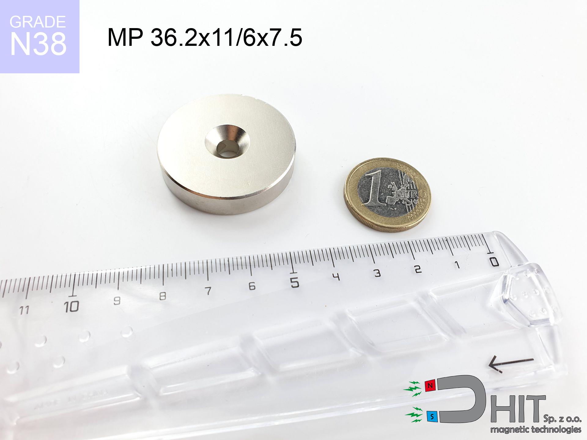
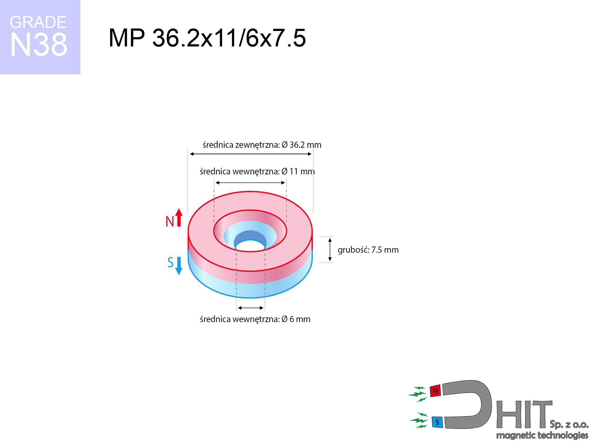
MP 36.2x11/6x7.5 / N38 - ring magnet
ring magnet
Catalog no 030248
GTIN/EAN: 5906301812241
Diameter
36.2 mm [±0,1 mm]
internal diameter Ø
11/6 mm [±0,1 mm]
Height
7.5 mm [±0,1 mm]
Weight
56.3 g
Magnetization Direction
↑ axial
Load capacity
17.12 kg / 167.95 N
Magnetic Induction
237.29 mT / 2373 Gs
Coating
[NiCuNi] Nickel
35.01 ZŁ with VAT / pcs + price for transport
28.46 ZŁ net + 23% VAT / pcs
bulk discounts:
Need more?Engineering report for this magnet
Full PDF analysis: pull and shear force, effect of distance, temperature and plate thickness, safety distances and the demagnetization curve.
Give us a call
+48 22 499 98 98
alternatively let us know through
request form
the contact section.
Weight as well as form of magnetic components can be analyzed using our
magnetic calculator.
Orders submitted before 14:00 will be dispatched today!
Technical data - MP 36.2x11/6x7.5 / N38 - ring magnet
Specification / characteristics - MP 36.2x11/6x7.5 / N38 - ring magnet
| properties | values |
|---|---|
| Cat. no. | 030248 |
| GTIN/EAN | 5906301812241 |
| Production/Distribution | Dhit sp. z o.o. |
| Country of origin | Poland / China / Germany |
| Customs code | 85059029 |
| Diameter | 36.2 mm [±0,1 mm] |
| internal diameter Ø | 11/6 mm [±0,1 mm] |
| Height | 7.5 mm [±0,1 mm] |
| Weight | 56.3 g |
| Magnetization Direction | ↑ axial |
| Load capacity ~ ? | 17.12 kg / 167.95 N |
| Magnetic Induction ~ ? | 237.29 mT / 2373 Gs |
| Coating | [NiCuNi] Nickel |
| Manufacturing Tolerance | ±0.1 mm |
Magnetic properties of material N38
| properties | values | units |
|---|---|---|
| remenance Br [min. - max.] ? | 12.2-12.6 | kGs |
| remenance Br [min. - max.] ? | 1220-1260 | mT |
| coercivity bHc ? | 10.8-11.5 | kOe |
| coercivity bHc ? | 860-915 | kA/m |
| actual internal force iHc | ≥ 12 | kOe |
| actual internal force iHc | ≥ 955 | kA/m |
| energy density [min. - max.] ? | 36-38 | BH max MGOe |
| energy density [min. - max.] ? | 287-303 | BH max KJ/m |
| max. temperature ? | ≤ 80 | °C |
Physical properties of sintered neodymium magnets Nd2Fe14B at 20°C
| properties | values | units |
|---|---|---|
| Vickers hardness | ≥550 | Hv |
| Density | ≥7.4 | g/cm3 |
| Curie Temperature TC | 312 - 380 | °C |
| Curie Temperature TF | 593 - 716 | °F |
| Specific resistance | 150 | μΩ⋅cm |
| Bending strength | 250 | MPa |
| Compressive strength | 1000~1100 | MPa |
| Thermal expansion parallel (∥) to orientation (M) | (3-4) x 10-6 | °C-1 |
| Thermal expansion perpendicular (⊥) to orientation (M) | -(1-3) x 10-6 | °C-1 |
| Young's modulus | 1.7 x 10⁴ | kg/mm² |
Physical modeling of the assembly - technical parameters
The following values represent the direct effect of a mathematical analysis. Values are based on algorithms for the material Nd2Fe14B. Real-world parameters may deviate from the simulation results. Please consider these calculations as a reference point when designing systems.
Table 1: Static force (force vs gap) - interaction chart
MP 36.2x11/6x7.5 / N38
| Distance (mm) | Induction (Gauss) / mT | Pull Force (kg/lbs/g/N) | Risk Status |
|---|---|---|---|
| 0 mm |
2059 Gs
205.9 mT
|
17.12 kg / 37.74 LBS
17120.0 g / 167.9 N
|
crushing |
| 1 mm |
1997 Gs
199.7 mT
|
16.11 kg / 35.52 LBS
16110.1 g / 158.0 N
|
crushing |
| 2 mm |
1923 Gs
192.3 mT
|
14.93 kg / 32.91 LBS
14925.7 g / 146.4 N
|
crushing |
| 3 mm |
1838 Gs
183.8 mT
|
13.64 kg / 30.06 LBS
13636.4 g / 133.8 N
|
crushing |
| 5 mm |
1648 Gs
164.8 mT
|
10.97 kg / 24.18 LBS
10968.0 g / 107.6 N
|
crushing |
| 10 mm |
1161 Gs
116.1 mT
|
5.44 kg / 12.00 LBS
5444.8 g / 53.4 N
|
warning |
| 15 mm |
775 Gs
77.5 mT
|
2.43 kg / 5.35 LBS
2427.5 g / 23.8 N
|
warning |
| 20 mm |
515 Gs
51.5 mT
|
1.07 kg / 2.36 LBS
1071.1 g / 10.5 N
|
weak grip |
| 30 mm |
242 Gs
24.2 mT
|
0.24 kg / 0.52 LBS
236.8 g / 2.3 N
|
weak grip |
| 50 mm |
73 Gs
7.3 mT
|
0.02 kg / 0.05 LBS
21.8 g / 0.2 N
|
weak grip |
Table 2: Slippage force (wall)
MP 36.2x11/6x7.5 / N38
| Distance (mm) | Friction coefficient | Pull Force (kg/lbs/g/N) |
|---|---|---|
| 0 mm | Stal (~0.2) |
3.42 kg / 7.55 LBS
3424.0 g / 33.6 N
|
| 1 mm | Stal (~0.2) |
3.22 kg / 7.10 LBS
3222.0 g / 31.6 N
|
| 2 mm | Stal (~0.2) |
2.99 kg / 6.58 LBS
2986.0 g / 29.3 N
|
| 3 mm | Stal (~0.2) |
2.73 kg / 6.01 LBS
2728.0 g / 26.8 N
|
| 5 mm | Stal (~0.2) |
2.19 kg / 4.84 LBS
2194.0 g / 21.5 N
|
| 10 mm | Stal (~0.2) |
1.09 kg / 2.40 LBS
1088.0 g / 10.7 N
|
| 15 mm | Stal (~0.2) |
0.49 kg / 1.07 LBS
486.0 g / 4.8 N
|
| 20 mm | Stal (~0.2) |
0.21 kg / 0.47 LBS
214.0 g / 2.1 N
|
| 30 mm | Stal (~0.2) |
0.05 kg / 0.11 LBS
48.0 g / 0.5 N
|
| 50 mm | Stal (~0.2) |
0.00 kg / 0.01 LBS
4.0 g / 0.0 N
|
Table 3: Vertical assembly (sliding) - behavior on slippery surfaces
MP 36.2x11/6x7.5 / N38
| Surface type | Friction coefficient / % Mocy | Max load (kg/lbs/g/N) |
|---|---|---|
| Raw steel |
µ = 0.3
30% Nominalnej Siły
|
5.14 kg / 11.32 LBS
5136.0 g / 50.4 N
|
| Painted steel (standard) |
µ = 0.2
20% Nominalnej Siły
|
3.42 kg / 7.55 LBS
3424.0 g / 33.6 N
|
| Oily/slippery steel |
µ = 0.1
10% Nominalnej Siły
|
1.71 kg / 3.77 LBS
1712.0 g / 16.8 N
|
| Magnet with anti-slip rubber |
µ = 0.5
50% Nominalnej Siły
|
8.56 kg / 18.87 LBS
8560.0 g / 84.0 N
|
Table 4: Material efficiency (substrate influence) - power losses
MP 36.2x11/6x7.5 / N38
| Steel thickness (mm) | % power | Real pull force (kg/lbs/g/N) |
|---|---|---|
| 0.5 mm |
|
0.86 kg / 1.89 LBS
856.0 g / 8.4 N
|
| 1 mm |
|
2.14 kg / 4.72 LBS
2140.0 g / 21.0 N
|
| 2 mm |
|
4.28 kg / 9.44 LBS
4280.0 g / 42.0 N
|
| 3 mm |
|
6.42 kg / 14.15 LBS
6420.0 g / 63.0 N
|
| 5 mm |
|
10.70 kg / 23.59 LBS
10700.0 g / 105.0 N
|
| 10 mm |
|
17.12 kg / 37.74 LBS
17120.0 g / 167.9 N
|
| 11 mm |
|
17.12 kg / 37.74 LBS
17120.0 g / 167.9 N
|
| 12 mm |
|
17.12 kg / 37.74 LBS
17120.0 g / 167.9 N
|
Table 5: Thermal stability (stability) - power drop
MP 36.2x11/6x7.5 / N38
| Ambient temp. (°C) | Power loss | Remaining pull (kg/lbs/g/N) | Status |
|---|---|---|---|
| 20 °C | 0.0% |
17.12 kg / 37.74 LBS
17120.0 g / 167.9 N
|
OK |
| 40 °C | -2.2% |
16.74 kg / 36.91 LBS
16743.4 g / 164.3 N
|
OK |
| 60 °C | -4.4% |
16.37 kg / 36.08 LBS
16366.7 g / 160.6 N
|
|
| 80 °C | -6.6% |
15.99 kg / 35.25 LBS
15990.1 g / 156.9 N
|
|
| 100 °C | -28.8% |
12.19 kg / 26.87 LBS
12189.4 g / 119.6 N
|
Table 6: Magnet-Magnet interaction (attraction) - field collision
MP 36.2x11/6x7.5 / N38
| Gap (mm) | Attraction (kg/lbs) (N-S) | Shear Strength (kg/lbs/g/N) | Repulsion (kg/lbs) (N-N) |
|---|---|---|---|
| 0 mm |
22.24 kg / 49.03 LBS
3 569 Gs
|
3.34 kg / 7.35 LBS
3336 g / 32.7 N
|
N/A |
| 1 mm |
21.62 kg / 47.67 LBS
4 061 Gs
|
3.24 kg / 7.15 LBS
3243 g / 31.8 N
|
19.46 kg / 42.90 LBS
~0 Gs
|
| 2 mm |
20.93 kg / 46.14 LBS
3 995 Gs
|
3.14 kg / 6.92 LBS
3139 g / 30.8 N
|
18.84 kg / 41.52 LBS
~0 Gs
|
| 3 mm |
20.18 kg / 44.49 LBS
3 923 Gs
|
3.03 kg / 6.67 LBS
3027 g / 29.7 N
|
18.16 kg / 40.04 LBS
~0 Gs
|
| 5 mm |
18.56 kg / 40.93 LBS
3 763 Gs
|
2.78 kg / 6.14 LBS
2785 g / 27.3 N
|
16.71 kg / 36.83 LBS
~0 Gs
|
| 10 mm |
14.25 kg / 31.41 LBS
3 296 Gs
|
2.14 kg / 4.71 LBS
2137 g / 21.0 N
|
12.82 kg / 28.27 LBS
~0 Gs
|
| 20 mm |
7.07 kg / 15.59 LBS
2 322 Gs
|
1.06 kg / 2.34 LBS
1061 g / 10.4 N
|
6.37 kg / 14.03 LBS
~0 Gs
|
| 50 mm |
0.64 kg / 1.40 LBS
697 Gs
|
0.10 kg / 0.21 LBS
96 g / 0.9 N
|
0.57 kg / 1.26 LBS
~0 Gs
|
| 60 mm |
0.31 kg / 0.68 LBS
484 Gs
|
0.05 kg / 0.10 LBS
46 g / 0.5 N
|
0.28 kg / 0.61 LBS
~0 Gs
|
| 70 mm |
0.16 kg / 0.35 LBS
346 Gs
|
0.02 kg / 0.05 LBS
24 g / 0.2 N
|
0.14 kg / 0.31 LBS
~0 Gs
|
| 80 mm |
0.08 kg / 0.19 LBS
254 Gs
|
0.01 kg / 0.03 LBS
13 g / 0.1 N
|
0.08 kg / 0.17 LBS
~0 Gs
|
| 90 mm |
0.05 kg / 0.11 LBS
191 Gs
|
0.01 kg / 0.02 LBS
7 g / 0.1 N
|
0.04 kg / 0.10 LBS
~0 Gs
|
| 100 mm |
0.03 kg / 0.06 LBS
147 Gs
|
0.00 kg / 0.01 LBS
4 g / 0.0 N
|
0.03 kg / 0.06 LBS
~0 Gs
|
Table 7: Safety (HSE) (implants) - warnings
MP 36.2x11/6x7.5 / N38
| Object / Device | Limit (Gauss) / mT | Safe distance |
|---|---|---|
| Pacemaker | 5 Gs (0.5 mT) | 13.5 cm |
| Hearing aid | 10 Gs (1.0 mT) | 10.5 cm |
| Timepiece | 20 Gs (2.0 mT) | 8.5 cm |
| Phone / Smartphone | 40 Gs (4.0 mT) | 6.5 cm |
| Remote | 50 Gs (5.0 mT) | 6.0 cm |
| Payment card | 400 Gs (40.0 mT) | 2.5 cm |
| HDD hard drive | 600 Gs (60.0 mT) | 2.0 cm |
Table 8: Dynamics (cracking risk) - warning
MP 36.2x11/6x7.5 / N38
| Start from (mm) | Speed (km/h) | Energy (J) | Predicted outcome |
|---|---|---|---|
| 10 mm |
20.79 km/h
(5.78 m/s)
|
0.94 J | |
| 30 mm |
30.72 km/h
(8.53 m/s)
|
2.05 J | |
| 50 mm |
39.36 km/h
(10.93 m/s)
|
3.36 J | |
| 100 mm |
55.61 km/h
(15.45 m/s)
|
6.72 J |
Table 9: Coating parameters (durability)
MP 36.2x11/6x7.5 / N38
| Technical parameter | Value / Description |
|---|---|
| Coating type | [NiCuNi] Nickel |
| Layer structure | Nickel - Copper - Nickel |
| Layer thickness | 10-20 µm |
| Salt spray test (SST) ? | 24 h |
| Recommended environment | Indoors only (dry) |
Table 10: Electrical data (Flux)
MP 36.2x11/6x7.5 / N38
| Parameter | Value | SI Unit / Description |
|---|---|---|
| Magnetic Flux | 21 038 Mx | 210.4 µWb |
| Pc Coefficient | 0.26 | Low (Flat) |
Table 11: Physics of underwater searching
MP 36.2x11/6x7.5 / N38
| Environment | Effective steel pull | Effect |
|---|---|---|
| Air (land) | 17.12 kg | Standard |
| Water (riverbed) |
19.60 kg
(+2.48 kg buoyancy gain)
|
+14.5% |
1. Wall mount (shear)
*Warning: On a vertical surface, the magnet holds only a fraction of its max power.
2. Steel thickness impact
*Thin metal sheet (e.g. computer case) severely limits the holding force.
3. Temperature resistance
*For N38 material, the critical limit is 80°C.
4. Demagnetization curve and operating point (B-H)
chart generated for the permeance coefficient Pc (Permeance Coefficient) = 0.26
This simulation demonstrates the magnetic stability of the selected magnet under specific geometric conditions. The solid red line represents the demagnetization curve (material potential), while the dashed blue line is the load line based on the magnet's geometry. The Pc (Permeance Coefficient), also known as the load line slope, is a dimensionless value that describes the relationship between the magnet's shape and its magnetic stability. The intersection of these two lines (the black dot) is the operating point — it determines the actual magnetic flux density generated by the magnet in this specific configuration. A higher Pc value means the magnet is more 'slender' (tall relative to its area), resulting in a higher operating point and better resistance to irreversible demagnetization caused by external fields or temperature. A value of 0.42 is relatively low (typical for flat magnets), meaning the operating point is closer to the 'knee' of the curve — caution is advised when operating at temperatures near the maximum limit to avoid strength loss.
Elemental analysis
| iron (Fe) | 64% – 68% |
| neodymium (Nd) | 29% – 32% |
| boron (B) | 1.1% – 1.2% |
| dysprosium (Dy) | 0.5% – 2.0% |
| coating (Ni-Cu-Ni) | < 0.05% |
Ecology and recycling (GPSR)
| recyclability (EoL) | 100% |
| recycled raw materials | ~10% (pre-cons) |
| carbon footprint | low / zredukowany |
| waste code (EWC) | 16 02 16 |
See more products
![UI 45x13x5 [M301] / N38 - badge holder](https://cdn3.dhit.pl/graphics/products/ui45x13x5-m301-vud.jpg "UI 45x13x5 [M301] / N38 - badge holder")

![SM 32x450 [2xM8] / N42 - magnetic separator](https://cdn3.dhit.pl/graphics/products/sm-32x450-2xm8-bex.jpg "SM 32x450 [2xM8] / N42 - magnetic separator")
![SM 32x100 [2xM8] / N42 - magnetic separator](https://cdn3.dhit.pl/graphics/products/sm-32x100-2xm8-cox.jpg "SM 32x100 [2xM8] / N42 - magnetic separator")
Advantages and disadvantages of neodymium magnets.
Benefits
- They retain attractive force for almost ten years – the drop is just ~1% (in theory),
- Neodymium magnets are characterized by exceptionally resistant to loss of magnetic properties caused by magnetic disturbances,
- Thanks to the smooth finish, the coating of Ni-Cu-Ni, gold, or silver-plated gives an professional appearance,
- The surface of neodymium magnets generates a intense magnetic field – this is a key feature,
- Thanks to resistance to high temperature, they are able to function (depending on the form) even at temperatures up to 230°C and higher...
- Possibility of exact shaping and adapting to atypical applications,
- Huge importance in modern industrial fields – they serve a role in computer drives, electric motors, medical equipment, also other advanced devices.
- Compactness – despite small sizes they provide effective action, making them ideal for precision applications
Weaknesses
- They are prone to damage upon too strong impacts. To avoid cracks, it is worth securing magnets in special housings. Such protection not only shields the magnet but also increases its resistance to damage
- Neodymium magnets decrease their force under the influence of heating. As soon as 80°C is exceeded, many of them start losing their force. Therefore, we recommend our special magnets marked [AH], which maintain durability even at temperatures up to 230°C
- Due to the susceptibility of magnets to corrosion in a humid environment, we recommend using waterproof magnets made of rubber, plastic or other material immune to moisture, when using outdoors
- Due to limitations in realizing threads and complicated shapes in magnets, we propose using cover - magnetic mechanism.
- Potential hazard resulting from small fragments of magnets are risky, in case of ingestion, which becomes key in the context of child health protection. Furthermore, tiny parts of these devices are able to disrupt the diagnostic process medical in case of swallowing.
- Due to complex production process, their price is higher than average,
Holding force characteristics
Magnetic strength at its maximum – what it depends on?
- on a plate made of mild steel, effectively closing the magnetic field
- whose thickness equals approx. 10 mm
- with an ideally smooth contact surface
- under conditions of no distance (metal-to-metal)
- under perpendicular application of breakaway force (90-degree angle)
- at temperature approx. 20 degrees Celsius
Determinants of practical lifting force of a magnet
- Gap between surfaces – even a fraction of a millimeter of distance (caused e.g. by varnish or unevenness) diminishes the magnet efficiency, often by half at just 0.5 mm.
- Load vector – highest force is available only during perpendicular pulling. The force required to slide of the magnet along the plate is usually several times lower (approx. 1/5 of the lifting capacity).
- Element thickness – to utilize 100% power, the steel must be adequately massive. Thin sheet limits the attraction force (the magnet "punches through" it).
- Steel grade – the best choice is pure iron steel. Stainless steels may have worse magnetic properties.
- Surface quality – the smoother and more polished the surface, the larger the contact zone and stronger the hold. Roughness acts like micro-gaps.
- Thermal environment – heating the magnet causes a temporary drop of force. Check the thermal limit for a given model.
Lifting capacity testing was performed on a smooth plate of optimal thickness, under a perpendicular pulling force, however under parallel forces the holding force is lower. Additionally, even a slight gap between the magnet and the plate reduces the load capacity.
Precautions when working with NdFeB magnets
Power loss in heat
Avoid heat. Neodymium magnets are susceptible to heat. If you need operation above 80°C, look for HT versions (H, SH, UH).
Magnets are brittle
Neodymium magnets are ceramic materials, which means they are fragile like glass. Impact of two magnets will cause them breaking into shards.
Keep away from electronics
A powerful magnetic field disrupts the operation of compasses in phones and navigation systems. Maintain magnets close to a device to prevent damaging the sensors.
Allergy Warning
It is widely known that the nickel plating (standard magnet coating) is a strong allergen. If you have an allergy, prevent touching magnets with bare hands or choose versions in plastic housing.
Cards and drives
Equipment safety: Strong magnets can ruin data carriers and delicate electronics (pacemakers, hearing aids, timepieces).
This is not a toy
Strictly keep magnets out of reach of children. Choking hazard is high, and the consequences of magnets connecting inside the body are tragic.
Crushing risk
Danger of trauma: The pulling power is so great that it can result in blood blisters, pinching, and broken bones. Protective gloves are recommended.
Pacemakers
For implant holders: Powerful magnets affect medical devices. Maintain minimum 30 cm distance or ask another person to work with the magnets.
Caution required
Before use, read the rules. Uncontrolled attraction can break the magnet or hurt your hand. Be predictive.
Combustion hazard
Drilling and cutting of NdFeB material poses a fire hazard. Magnetic powder oxidizes rapidly with oxygen and is difficult to extinguish.
Tabela kosztu i czasu dostawy
Płatność przed wysyłką:

GLS kurier
Przesyłka będzie u Ciebie za 2-3 dni
14.99 ZŁ

InPost Paczkomaty 24/7
Przesyłka będzie u Ciebie za 1-2 dni
12.30 ZŁ
Płatność przy odbiorze (pobranie):
GLS kurier
Przesyłka będzie u Ciebie za 1-2 dni
23.00 ZŁ
Rate the product
Your rating