
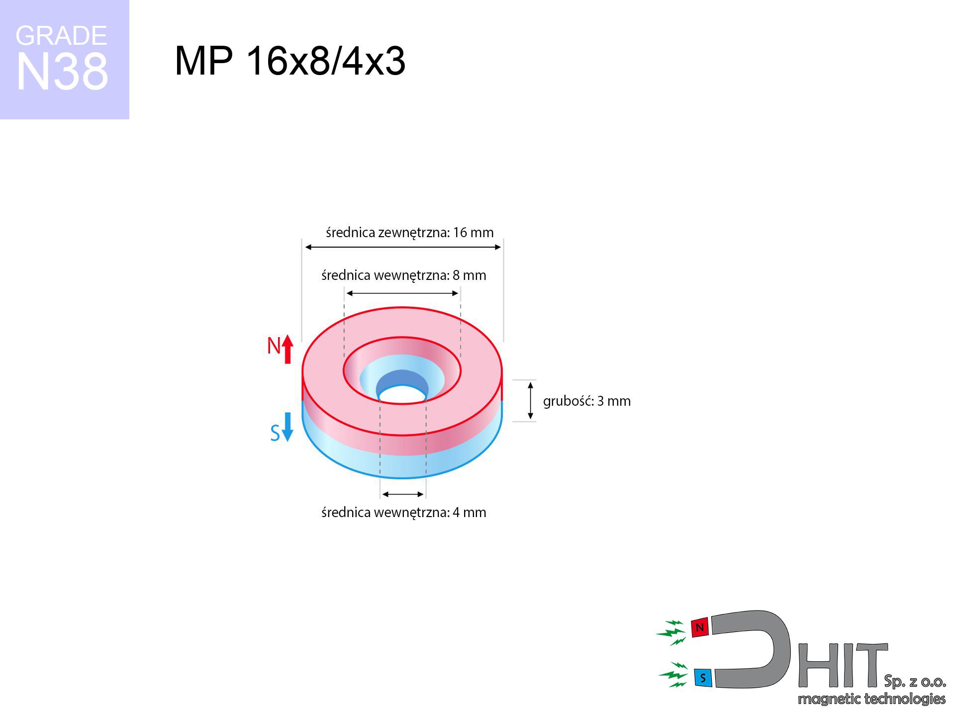
MP 16x8/4x3 / N38 - ring magnet
ring magnet
Catalog no 030396
GTIN/EAN: 5906301812333
Diameter
16 mm [±0,1 mm]
internal diameter Ø
8/4 mm [±0,1 mm]
Height
3 mm [±0,1 mm]
Weight
4.24 g
Magnetization Direction
↑ axial
Load capacity
2.78 kg / 27.29 N
Magnetic Induction
217.61 mT / 2176 Gs
Coating
[NiCuNi] Nickel
2.50 ZŁ with VAT / pcs + price for transport
2.03 ZŁ net + 23% VAT / pcs
bulk discounts:
Need more?
Give us a call
+48 22 499 98 98
alternatively let us know using
request form
the contact section.
Weight and form of a neodymium magnet can be calculated on our
force calculator.
Same-day shipping for orders placed before 14:00.
Technical of the product - MP 16x8/4x3 / N38 - ring magnet
Specification / characteristics - MP 16x8/4x3 / N38 - ring magnet
| properties | values |
|---|---|
| Cat. no. | 030396 |
| GTIN/EAN | 5906301812333 |
| Production/Distribution | Dhit sp. z o.o. |
| Country of origin | Poland / China / Germany |
| Customs code | 85059029 |
| Diameter | 16 mm [±0,1 mm] |
| internal diameter Ø | 8/4 mm [±0,1 mm] |
| Height | 3 mm [±0,1 mm] |
| Weight | 4.24 g |
| Magnetization Direction | ↑ axial |
| Load capacity ~ ? | 2.78 kg / 27.29 N |
| Magnetic Induction ~ ? | 217.61 mT / 2176 Gs |
| Coating | [NiCuNi] Nickel |
| Manufacturing Tolerance | ±0.1 mm |
Magnetic properties of material N38
| properties | values | units |
|---|---|---|
| remenance Br [min. - max.] ? | 12.2-12.6 | kGs |
| remenance Br [min. - max.] ? | 1220-1260 | mT |
| coercivity bHc ? | 10.8-11.5 | kOe |
| coercivity bHc ? | 860-915 | kA/m |
| actual internal force iHc | ≥ 12 | kOe |
| actual internal force iHc | ≥ 955 | kA/m |
| energy density [min. - max.] ? | 36-38 | BH max MGOe |
| energy density [min. - max.] ? | 287-303 | BH max KJ/m |
| max. temperature ? | ≤ 80 | °C |
Physical properties of sintered neodymium magnets Nd2Fe14B at 20°C
| properties | values | units |
|---|---|---|
| Vickers hardness | ≥550 | Hv |
| Density | ≥7.4 | g/cm3 |
| Curie Temperature TC | 312 - 380 | °C |
| Curie Temperature TF | 593 - 716 | °F |
| Specific resistance | 150 | μΩ⋅cm |
| Bending strength | 250 | MPa |
| Compressive strength | 1000~1100 | MPa |
| Thermal expansion parallel (∥) to orientation (M) | (3-4) x 10-6 | °C-1 |
| Thermal expansion perpendicular (⊥) to orientation (M) | -(1-3) x 10-6 | °C-1 |
| Young's modulus | 1.7 x 10⁴ | kg/mm² |
Technical modeling of the magnet - technical parameters
The following values constitute the direct effect of a engineering calculation. Results rely on algorithms for the material Nd2Fe14B. Real-world parameters may deviate from the simulation results. Please consider these calculations as a reference point when designing systems.
Table 1: Static pull force (force vs distance) - characteristics
MP 16x8/4x3 / N38
| Distance (mm) | Induction (Gauss) / mT | Pull Force (kg/lbs/g/N) | Risk Status |
|---|---|---|---|
| 0 mm |
1882 Gs
188.2 mT
|
2.78 kg / 6.13 LBS
2780.0 g / 27.3 N
|
warning |
| 1 mm |
1746 Gs
174.6 mT
|
2.39 kg / 5.27 LBS
2392.4 g / 23.5 N
|
warning |
| 2 mm |
1561 Gs
156.1 mT
|
1.91 kg / 4.22 LBS
1913.9 g / 18.8 N
|
safe |
| 3 mm |
1357 Gs
135.7 mT
|
1.45 kg / 3.19 LBS
1445.8 g / 14.2 N
|
safe |
| 5 mm |
969 Gs
96.9 mT
|
0.74 kg / 1.63 LBS
737.7 g / 7.2 N
|
safe |
| 10 mm |
387 Gs
38.7 mT
|
0.12 kg / 0.26 LBS
117.4 g / 1.2 N
|
safe |
| 15 mm |
171 Gs
17.1 mT
|
0.02 kg / 0.05 LBS
22.9 g / 0.2 N
|
safe |
| 20 mm |
87 Gs
8.7 mT
|
0.01 kg / 0.01 LBS
5.9 g / 0.1 N
|
safe |
| 30 mm |
30 Gs
3.0 mT
|
0.00 kg / 0.00 LBS
0.7 g / 0.0 N
|
safe |
| 50 mm |
7 Gs
0.7 mT
|
0.00 kg / 0.00 LBS
0.0 g / 0.0 N
|
safe |
Table 2: Vertical force (wall)
MP 16x8/4x3 / N38
| Distance (mm) | Friction coefficient | Pull Force (kg/lbs/g/N) |
|---|---|---|
| 0 mm | Stal (~0.2) |
0.56 kg / 1.23 LBS
556.0 g / 5.5 N
|
| 1 mm | Stal (~0.2) |
0.48 kg / 1.05 LBS
478.0 g / 4.7 N
|
| 2 mm | Stal (~0.2) |
0.38 kg / 0.84 LBS
382.0 g / 3.7 N
|
| 3 mm | Stal (~0.2) |
0.29 kg / 0.64 LBS
290.0 g / 2.8 N
|
| 5 mm | Stal (~0.2) |
0.15 kg / 0.33 LBS
148.0 g / 1.5 N
|
| 10 mm | Stal (~0.2) |
0.02 kg / 0.05 LBS
24.0 g / 0.2 N
|
| 15 mm | Stal (~0.2) |
0.00 kg / 0.01 LBS
4.0 g / 0.0 N
|
| 20 mm | Stal (~0.2) |
0.00 kg / 0.00 LBS
2.0 g / 0.0 N
|
| 30 mm | Stal (~0.2) |
0.00 kg / 0.00 LBS
0.0 g / 0.0 N
|
| 50 mm | Stal (~0.2) |
0.00 kg / 0.00 LBS
0.0 g / 0.0 N
|
Table 3: Vertical assembly (shearing) - behavior on slippery surfaces
MP 16x8/4x3 / N38
| Surface type | Friction coefficient / % Mocy | Max load (kg/lbs/g/N) |
|---|---|---|
| Raw steel |
µ = 0.3
30% Nominalnej Siły
|
0.83 kg / 1.84 LBS
834.0 g / 8.2 N
|
| Painted steel (standard) |
µ = 0.2
20% Nominalnej Siły
|
0.56 kg / 1.23 LBS
556.0 g / 5.5 N
|
| Oily/slippery steel |
µ = 0.1
10% Nominalnej Siły
|
0.28 kg / 0.61 LBS
278.0 g / 2.7 N
|
| Magnet with anti-slip rubber |
µ = 0.5
50% Nominalnej Siły
|
1.39 kg / 3.06 LBS
1390.0 g / 13.6 N
|
Table 4: Steel thickness (substrate influence) - power losses
MP 16x8/4x3 / N38
| Steel thickness (mm) | % power | Real pull force (kg/lbs/g/N) |
|---|---|---|
| 0.5 mm |
|
0.28 kg / 0.61 LBS
278.0 g / 2.7 N
|
| 1 mm |
|
0.70 kg / 1.53 LBS
695.0 g / 6.8 N
|
| 2 mm |
|
1.39 kg / 3.06 LBS
1390.0 g / 13.6 N
|
| 3 mm |
|
2.09 kg / 4.60 LBS
2085.0 g / 20.5 N
|
| 5 mm |
|
2.78 kg / 6.13 LBS
2780.0 g / 27.3 N
|
| 10 mm |
|
2.78 kg / 6.13 LBS
2780.0 g / 27.3 N
|
| 11 mm |
|
2.78 kg / 6.13 LBS
2780.0 g / 27.3 N
|
| 12 mm |
|
2.78 kg / 6.13 LBS
2780.0 g / 27.3 N
|
Table 5: Thermal resistance (material behavior) - resistance threshold
MP 16x8/4x3 / N38
| Ambient temp. (°C) | Power loss | Remaining pull (kg/lbs/g/N) | Status |
|---|---|---|---|
| 20 °C | 0.0% |
2.78 kg / 6.13 LBS
2780.0 g / 27.3 N
|
OK |
| 40 °C | -2.2% |
2.72 kg / 5.99 LBS
2718.8 g / 26.7 N
|
OK |
| 60 °C | -4.4% |
2.66 kg / 5.86 LBS
2657.7 g / 26.1 N
|
|
| 80 °C | -6.6% |
2.60 kg / 5.72 LBS
2596.5 g / 25.5 N
|
|
| 100 °C | -28.8% |
1.98 kg / 4.36 LBS
1979.4 g / 19.4 N
|
Table 6: Magnet-Magnet interaction (repulsion) - field collision
MP 16x8/4x3 / N38
| Gap (mm) | Attraction (kg/lbs) (N-S) | Lateral Force (kg/lbs/g/N) | Repulsion (kg/lbs) (N-N) |
|---|---|---|---|
| 0 mm |
3.50 kg / 7.71 LBS
3 330 Gs
|
0.52 kg / 1.16 LBS
525 g / 5.1 N
|
N/A |
| 1 mm |
3.28 kg / 7.23 LBS
3 644 Gs
|
0.49 kg / 1.08 LBS
492 g / 4.8 N
|
2.95 kg / 6.51 LBS
~0 Gs
|
| 2 mm |
3.01 kg / 6.64 LBS
3 492 Gs
|
0.45 kg / 1.00 LBS
452 g / 4.4 N
|
2.71 kg / 5.97 LBS
~0 Gs
|
| 3 mm |
2.71 kg / 5.98 LBS
3 316 Gs
|
0.41 kg / 0.90 LBS
407 g / 4.0 N
|
2.44 kg / 5.39 LBS
~0 Gs
|
| 5 mm |
2.11 kg / 4.64 LBS
2 920 Gs
|
0.32 kg / 0.70 LBS
316 g / 3.1 N
|
1.90 kg / 4.18 LBS
~0 Gs
|
| 10 mm |
0.93 kg / 2.05 LBS
1 939 Gs
|
0.14 kg / 0.31 LBS
139 g / 1.4 N
|
0.84 kg / 1.84 LBS
~0 Gs
|
| 20 mm |
0.15 kg / 0.33 LBS
773 Gs
|
0.02 kg / 0.05 LBS
22 g / 0.2 N
|
0.13 kg / 0.29 LBS
~0 Gs
|
| 50 mm |
0.00 kg / 0.01 LBS
98 Gs
|
0.00 kg / 0.00 LBS
0 g / 0.0 N
|
0.00 kg / 0.00 LBS
~0 Gs
|
| 60 mm |
0.00 kg / 0.00 LBS
60 Gs
|
0.00 kg / 0.00 LBS
0 g / 0.0 N
|
0.00 kg / 0.00 LBS
~0 Gs
|
| 70 mm |
0.00 kg / 0.00 LBS
40 Gs
|
0.00 kg / 0.00 LBS
0 g / 0.0 N
|
0.00 kg / 0.00 LBS
~0 Gs
|
| 80 mm |
0.00 kg / 0.00 LBS
27 Gs
|
0.00 kg / 0.00 LBS
0 g / 0.0 N
|
0.00 kg / 0.00 LBS
~0 Gs
|
| 90 mm |
0.00 kg / 0.00 LBS
20 Gs
|
0.00 kg / 0.00 LBS
0 g / 0.0 N
|
0.00 kg / 0.00 LBS
~0 Gs
|
| 100 mm |
0.00 kg / 0.00 LBS
14 Gs
|
0.00 kg / 0.00 LBS
0 g / 0.0 N
|
0.00 kg / 0.00 LBS
~0 Gs
|
Table 7: Protective zones (electronics) - warnings
MP 16x8/4x3 / N38
| Object / Device | Limit (Gauss) / mT | Safe distance |
|---|---|---|
| Pacemaker | 5 Gs (0.5 mT) | 6.0 cm |
| Hearing aid | 10 Gs (1.0 mT) | 4.5 cm |
| Timepiece | 20 Gs (2.0 mT) | 3.5 cm |
| Phone / Smartphone | 40 Gs (4.0 mT) | 3.0 cm |
| Car key | 50 Gs (5.0 mT) | 2.5 cm |
| Payment card | 400 Gs (40.0 mT) | 1.0 cm |
| HDD hard drive | 600 Gs (60.0 mT) | 1.0 cm |
Table 8: Impact energy (cracking risk) - collision effects
MP 16x8/4x3 / N38
| Start from (mm) | Speed (km/h) | Energy (J) | Predicted outcome |
|---|---|---|---|
| 10 mm |
26.50 km/h
(7.36 m/s)
|
0.11 J | |
| 30 mm |
44.74 km/h
(12.43 m/s)
|
0.33 J | |
| 50 mm |
57.74 km/h
(16.04 m/s)
|
0.55 J | |
| 100 mm |
81.66 km/h
(22.68 m/s)
|
1.09 J |
Table 9: Corrosion resistance
MP 16x8/4x3 / N38
| Technical parameter | Value / Description |
|---|---|
| Coating type | [NiCuNi] Nickel |
| Layer structure | Nickel - Copper - Nickel |
| Layer thickness | 10-20 µm |
| Salt spray test (SST) ? | 24 h |
| Recommended environment | Indoors only (dry) |
Table 10: Electrical data (Flux)
MP 16x8/4x3 / N38
| Parameter | Value | SI Unit / Description |
|---|---|---|
| Magnetic Flux | 3 743 Mx | 37.4 µWb |
| Pc Coefficient | 0.24 | Low (Flat) |
Table 11: Physics of underwater searching
MP 16x8/4x3 / N38
| Environment | Effective steel pull | Effect |
|---|---|---|
| Air (land) | 2.78 kg | Standard |
| Water (riverbed) |
3.18 kg
(+0.40 kg buoyancy gain)
|
+14.5% |
1. Vertical hold
*Note: On a vertical wall, the magnet retains just a fraction of its perpendicular strength.
2. Steel thickness impact
*Thin metal sheet (e.g. 0.5mm PC case) drastically limits the holding force.
3. Thermal stability
*For N38 grade, the critical limit is 80°C.
4. Demagnetization curve and operating point (B-H)
chart generated for the permeance coefficient Pc (Permeance Coefficient) = 0.24
The chart above illustrates the magnetic characteristics of the material within the second quadrant of the hysteresis loop. The solid red line represents the demagnetization curve (material potential), while the dashed blue line is the load line based on the magnet's geometry. The Pc (Permeance Coefficient), also known as the load line slope, is a dimensionless value that describes the relationship between the magnet's shape and its magnetic stability. The intersection of these two lines (the black dot) is the operating point — it determines the actual magnetic flux density generated by the magnet in this specific configuration. A higher Pc value means the magnet is more 'slender' (tall relative to its area), resulting in a higher operating point and better resistance to irreversible demagnetization caused by external fields or temperature. A value of 0.42 is relatively low (typical for flat magnets), meaning the operating point is closer to the 'knee' of the curve — caution is advised when operating at temperatures near the maximum limit to avoid strength loss.
Chemical composition
| iron (Fe) | 64% – 68% |
| neodymium (Nd) | 29% – 32% |
| boron (B) | 1.1% – 1.2% |
| dysprosium (Dy) | 0.5% – 2.0% |
| coating (Ni-Cu-Ni) | < 0.05% |
Ecology and recycling (GPSR)
| recyclability (EoL) | 100% |
| recycled raw materials | ~10% (pre-cons) |
| carbon footprint | low / zredukowany |
| waste code (EWC) | 16 02 16 |
Other products


![HH 25x7.7 [M5] / N38 - through hole magnetic holder](https://cdn3.dhit.pl/graphics/products/hh-25x7.7-m5-pov.jpg "HH 25x7.7 [M5] / N38 - through hole magnetic holder")

Strengths and weaknesses of rare earth magnets.
Advantages
- They have constant strength, and over around ten years their performance decreases symbolically – ~1% (according to theory),
- They possess excellent resistance to weakening of magnetic properties as a result of external magnetic sources,
- By applying a reflective coating of silver, the element has an modern look,
- Magnets are distinguished by excellent magnetic induction on the outer layer,
- Neodymium magnets are characterized by very high magnetic induction on the magnet surface and can function (depending on the shape) even at a temperature of 230°C or more...
- Possibility of precise creating as well as modifying to specific conditions,
- Universal use in electronics industry – they are used in HDD drives, brushless drives, medical devices, also other advanced devices.
- Relatively small size with high pulling force – neodymium magnets offer high power in tiny dimensions, which allows their use in compact constructions
Limitations
- Brittleness is one of their disadvantages. Upon intense impact they can fracture. We advise keeping them in a steel housing, which not only secures them against impacts but also increases their durability
- We warn that neodymium magnets can lose their power at high temperatures. To prevent this, we advise our specialized [AH] magnets, which work effectively even at 230°C.
- They rust in a humid environment - during use outdoors we recommend using waterproof magnets e.g. in rubber, plastic
- We suggest cover - magnetic mount, due to difficulties in producing nuts inside the magnet and complex forms.
- Possible danger related to microscopic parts of magnets are risky, when accidentally swallowed, which gains importance in the context of child health protection. Furthermore, tiny parts of these products are able to complicate diagnosis medical in case of swallowing.
- With mass production the cost of neodymium magnets is economically unviable,
Holding force characteristics
Best holding force of the magnet in ideal parameters – what it depends on?
- with the application of a sheet made of low-carbon steel, guaranteeing full magnetic saturation
- with a cross-section of at least 10 mm
- characterized by even structure
- under conditions of ideal adhesion (metal-to-metal)
- during pulling in a direction vertical to the mounting surface
- in temp. approx. 20°C
Practical aspects of lifting capacity – factors
- Distance – the presence of foreign body (paint, dirt, gap) interrupts the magnetic circuit, which lowers power rapidly (even by 50% at 0.5 mm).
- Load vector – maximum parameter is obtained only during perpendicular pulling. The resistance to sliding of the magnet along the plate is usually several times lower (approx. 1/5 of the lifting capacity).
- Element thickness – to utilize 100% power, the steel must be adequately massive. Paper-thin metal restricts the attraction force (the magnet "punches through" it).
- Steel grade – the best choice is high-permeability steel. Stainless steels may attract less.
- Base smoothness – the smoother and more polished the surface, the better the adhesion and higher the lifting capacity. Unevenness acts like micro-gaps.
- Temperature influence – high temperature weakens magnetic field. Too high temperature can permanently damage the magnet.
Lifting capacity was assessed with the use of a smooth steel plate of suitable thickness (min. 20 mm), under vertically applied force, whereas under shearing force the lifting capacity is smaller. In addition, even a minimal clearance between the magnet’s surface and the plate reduces the lifting capacity.
Safe handling of NdFeB magnets
Do not drill into magnets
Powder created during machining of magnets is self-igniting. Avoid drilling into magnets unless you are an expert.
Conscious usage
Exercise caution. Rare earth magnets act from a distance and snap with huge force, often quicker than you can move away.
Heat sensitivity
Control the heat. Exposing the magnet above 80 degrees Celsius will permanently weaken its properties and pulling force.
GPS and phone interference
Note: rare earth magnets generate a field that disrupts sensitive sensors. Maintain a separation from your mobile, device, and GPS.
Medical implants
For implant holders: Powerful magnets disrupt electronics. Maintain at least 30 cm distance or ask another person to work with the magnets.
Bone fractures
Big blocks can crush fingers in a fraction of a second. Under no circumstances place your hand betwixt two strong magnets.
Do not give to children
Strictly store magnets away from children. Risk of swallowing is high, and the consequences of magnets clamping inside the body are fatal.
Risk of cracking
Despite metallic appearance, neodymium is brittle and cannot withstand shocks. Avoid impacts, as the magnet may crumble into sharp, dangerous pieces.
Safe distance
Powerful magnetic fields can corrupt files on payment cards, HDDs, and other magnetic media. Keep a distance of at least 10 cm.
Allergic reactions
Medical facts indicate that nickel (standard magnet coating) is a potent allergen. For allergy sufferers, avoid direct skin contact or select versions in plastic housing.
Tabela kosztu i czasu dostawy
Płatność przed wysyłką:

GLS kurier
Przesyłka będzie u Ciebie za 2-3 dni
14.99 ZŁ

InPost Paczkomaty 24/7
Przesyłka będzie u Ciebie za 1-2 dni
12.30 ZŁ
Płatność przy odbiorze (pobranie):
GLS kurier
Przesyłka będzie u Ciebie za 1-2 dni
23.00 ZŁ
Rate the product
Your rating