
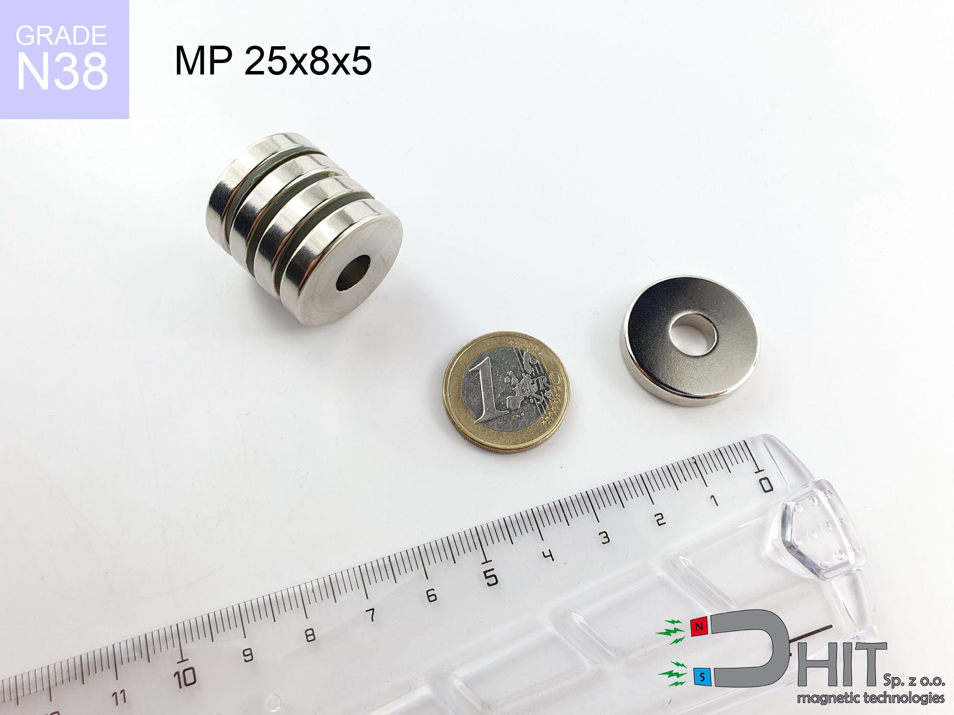
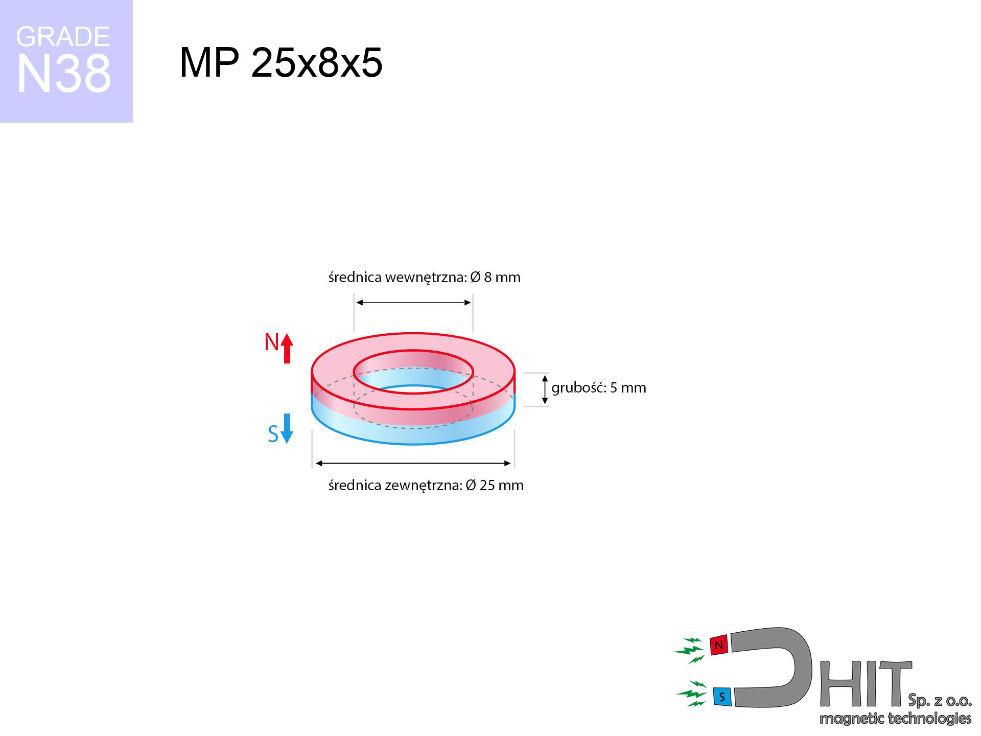
MP 25x8x5 / N38 - ring magnet
ring magnet
Catalog no 030196
GTIN/EAN: 5906301812135
Diameter
25 mm [±0,1 mm]
internal diameter Ø
8 mm [±0,1 mm]
Height
5 mm [±0,1 mm]
Weight
16.52 g
Magnetization Direction
↑ axial
Load capacity
7.16 kg / 70.21 N
Magnetic Induction
230.20 mT / 2302 Gs
Coating
[NiCuNi] Nickel
5.90 ZŁ with VAT / pcs + price for transport
4.80 ZŁ net + 23% VAT / pcs
bulk discounts:
Need more?
Contact us by phone
+48 888 99 98 98
if you prefer send us a note using
inquiry form
our website.
Lifting power along with shape of a neodymium magnet can be checked with our
modular calculator.
Same-day shipping for orders placed before 14:00.
Product card - MP 25x8x5 / N38 - ring magnet
Specification / characteristics - MP 25x8x5 / N38 - ring magnet
| properties | values |
|---|---|
| Cat. no. | 030196 |
| GTIN/EAN | 5906301812135 |
| Production/Distribution | Dhit sp. z o.o. |
| Country of origin | Poland / China / Germany |
| Customs code | 85059029 |
| Diameter | 25 mm [±0,1 mm] |
| internal diameter Ø | 8 mm [±0,1 mm] |
| Height | 5 mm [±0,1 mm] |
| Weight | 16.52 g |
| Magnetization Direction | ↑ axial |
| Load capacity ~ ? | 7.16 kg / 70.21 N |
| Magnetic Induction ~ ? | 230.20 mT / 2302 Gs |
| Coating | [NiCuNi] Nickel |
| Manufacturing Tolerance | ±0.1 mm |
Magnetic properties of material N38
| properties | values | units |
|---|---|---|
| remenance Br [min. - max.] ? | 12.2-12.6 | kGs |
| remenance Br [min. - max.] ? | 1220-1260 | mT |
| coercivity bHc ? | 10.8-11.5 | kOe |
| coercivity bHc ? | 860-915 | kA/m |
| actual internal force iHc | ≥ 12 | kOe |
| actual internal force iHc | ≥ 955 | kA/m |
| energy density [min. - max.] ? | 36-38 | BH max MGOe |
| energy density [min. - max.] ? | 287-303 | BH max KJ/m |
| max. temperature ? | ≤ 80 | °C |
Physical properties of sintered neodymium magnets Nd2Fe14B at 20°C
| properties | values | units |
|---|---|---|
| Vickers hardness | ≥550 | Hv |
| Density | ≥7.4 | g/cm3 |
| Curie Temperature TC | 312 - 380 | °C |
| Curie Temperature TF | 593 - 716 | °F |
| Specific resistance | 150 | μΩ⋅cm |
| Bending strength | 250 | MPa |
| Compressive strength | 1000~1100 | MPa |
| Thermal expansion parallel (∥) to orientation (M) | (3-4) x 10-6 | °C-1 |
| Thermal expansion perpendicular (⊥) to orientation (M) | -(1-3) x 10-6 | °C-1 |
| Young's modulus | 1.7 x 10⁴ | kg/mm² |
Engineering simulation of the magnet - report
The following data constitute the outcome of a physical simulation. Values were calculated on algorithms for the material Nd2Fe14B. Operational parameters might slightly differ from theoretical values. Use these calculations as a preliminary roadmap for designers.
Table 1: Static force (force vs distance) - power drop
MP 25x8x5 / N38
| Distance (mm) | Induction (Gauss) / mT | Pull Force (kg/lbs/g/N) | Risk Status |
|---|---|---|---|
| 0 mm |
5777 Gs
577.7 mT
|
7.16 kg / 15.79 pounds
7160.0 g / 70.2 N
|
strong |
| 1 mm |
5310 Gs
531.0 mT
|
6.05 kg / 13.33 pounds
6048.6 g / 59.3 N
|
strong |
| 2 mm |
4846 Gs
484.6 mT
|
5.04 kg / 11.10 pounds
5036.9 g / 49.4 N
|
strong |
| 3 mm |
4397 Gs
439.7 mT
|
4.15 kg / 9.15 pounds
4148.2 g / 40.7 N
|
strong |
| 5 mm |
3576 Gs
357.6 mT
|
2.74 kg / 6.05 pounds
2743.2 g / 26.9 N
|
strong |
| 10 mm |
2073 Gs
207.3 mT
|
0.92 kg / 2.03 pounds
921.6 g / 9.0 N
|
weak grip |
| 15 mm |
1231 Gs
123.1 mT
|
0.33 kg / 0.72 pounds
325.2 g / 3.2 N
|
weak grip |
| 20 mm |
773 Gs
77.3 mT
|
0.13 kg / 0.28 pounds
128.0 g / 1.3 N
|
weak grip |
| 30 mm |
356 Gs
35.6 mT
|
0.03 kg / 0.06 pounds
27.2 g / 0.3 N
|
weak grip |
| 50 mm |
115 Gs
11.5 mT
|
0.00 kg / 0.01 pounds
2.8 g / 0.0 N
|
weak grip |
Table 2: Vertical load (vertical surface)
MP 25x8x5 / N38
| Distance (mm) | Friction coefficient | Pull Force (kg/lbs/g/N) |
|---|---|---|
| 0 mm | Stal (~0.2) |
1.43 kg / 3.16 pounds
1432.0 g / 14.0 N
|
| 1 mm | Stal (~0.2) |
1.21 kg / 2.67 pounds
1210.0 g / 11.9 N
|
| 2 mm | Stal (~0.2) |
1.01 kg / 2.22 pounds
1008.0 g / 9.9 N
|
| 3 mm | Stal (~0.2) |
0.83 kg / 1.83 pounds
830.0 g / 8.1 N
|
| 5 mm | Stal (~0.2) |
0.55 kg / 1.21 pounds
548.0 g / 5.4 N
|
| 10 mm | Stal (~0.2) |
0.18 kg / 0.41 pounds
184.0 g / 1.8 N
|
| 15 mm | Stal (~0.2) |
0.07 kg / 0.15 pounds
66.0 g / 0.6 N
|
| 20 mm | Stal (~0.2) |
0.03 kg / 0.06 pounds
26.0 g / 0.3 N
|
| 30 mm | Stal (~0.2) |
0.01 kg / 0.01 pounds
6.0 g / 0.1 N
|
| 50 mm | Stal (~0.2) |
0.00 kg / 0.00 pounds
0.0 g / 0.0 N
|
Table 3: Vertical assembly (sliding) - behavior on slippery surfaces
MP 25x8x5 / N38
| Surface type | Friction coefficient / % Mocy | Max load (kg/lbs/g/N) |
|---|---|---|
| Raw steel |
µ = 0.3
30% Nominalnej Siły
|
2.15 kg / 4.74 pounds
2148.0 g / 21.1 N
|
| Painted steel (standard) |
µ = 0.2
20% Nominalnej Siły
|
1.43 kg / 3.16 pounds
1432.0 g / 14.0 N
|
| Oily/slippery steel |
µ = 0.1
10% Nominalnej Siły
|
0.72 kg / 1.58 pounds
716.0 g / 7.0 N
|
| Magnet with anti-slip rubber |
µ = 0.5
50% Nominalnej Siły
|
3.58 kg / 7.89 pounds
3580.0 g / 35.1 N
|
Table 4: Steel thickness (substrate influence) - sheet metal selection
MP 25x8x5 / N38
| Steel thickness (mm) | % power | Real pull force (kg/lbs/g/N) |
|---|---|---|
| 0.5 mm |
|
0.72 kg / 1.58 pounds
716.0 g / 7.0 N
|
| 1 mm |
|
1.79 kg / 3.95 pounds
1790.0 g / 17.6 N
|
| 2 mm |
|
3.58 kg / 7.89 pounds
3580.0 g / 35.1 N
|
| 3 mm |
|
5.37 kg / 11.84 pounds
5370.0 g / 52.7 N
|
| 5 mm |
|
7.16 kg / 15.79 pounds
7160.0 g / 70.2 N
|
| 10 mm |
|
7.16 kg / 15.79 pounds
7160.0 g / 70.2 N
|
| 11 mm |
|
7.16 kg / 15.79 pounds
7160.0 g / 70.2 N
|
| 12 mm |
|
7.16 kg / 15.79 pounds
7160.0 g / 70.2 N
|
Table 5: Working in heat (material behavior) - power drop
MP 25x8x5 / N38
| Ambient temp. (°C) | Power loss | Remaining pull (kg/lbs/g/N) | Status |
|---|---|---|---|
| 20 °C | 0.0% |
7.16 kg / 15.79 pounds
7160.0 g / 70.2 N
|
OK |
| 40 °C | -2.2% |
7.00 kg / 15.44 pounds
7002.5 g / 68.7 N
|
OK |
| 60 °C | -4.4% |
6.84 kg / 15.09 pounds
6845.0 g / 67.1 N
|
OK |
| 80 °C | -6.6% |
6.69 kg / 14.74 pounds
6687.4 g / 65.6 N
|
|
| 100 °C | -28.8% |
5.10 kg / 11.24 pounds
5097.9 g / 50.0 N
|
Table 6: Magnet-Magnet interaction (repulsion) - field range
MP 25x8x5 / N38
| Gap (mm) | Attraction (kg/lbs) (N-S) | Lateral Force (kg/lbs/g/N) | Repulsion (kg/lbs) (N-N) |
|---|---|---|---|
| 0 mm |
82.42 kg / 181.72 pounds
6 082 Gs
|
12.36 kg / 27.26 pounds
12364 g / 121.3 N
|
N/A |
| 1 mm |
75.95 kg / 167.44 pounds
11 091 Gs
|
11.39 kg / 25.12 pounds
11392 g / 111.8 N
|
68.35 kg / 150.69 pounds
~0 Gs
|
| 2 mm |
69.63 kg / 153.51 pounds
10 620 Gs
|
10.44 kg / 23.03 pounds
10445 g / 102.5 N
|
62.67 kg / 138.16 pounds
~0 Gs
|
| 3 mm |
63.64 kg / 140.29 pounds
10 153 Gs
|
9.55 kg / 21.04 pounds
9545 g / 93.6 N
|
57.27 kg / 126.26 pounds
~0 Gs
|
| 5 mm |
52.69 kg / 116.16 pounds
9 238 Gs
|
7.90 kg / 17.42 pounds
7903 g / 77.5 N
|
47.42 kg / 104.54 pounds
~0 Gs
|
| 10 mm |
31.58 kg / 69.62 pounds
7 152 Gs
|
4.74 kg / 10.44 pounds
4737 g / 46.5 N
|
28.42 kg / 62.66 pounds
~0 Gs
|
| 20 mm |
10.61 kg / 23.39 pounds
4 145 Gs
|
1.59 kg / 3.51 pounds
1591 g / 15.6 N
|
9.55 kg / 21.05 pounds
~0 Gs
|
| 50 mm |
0.65 kg / 1.43 pounds
1 024 Gs
|
0.10 kg / 0.21 pounds
97 g / 1.0 N
|
0.58 kg / 1.28 pounds
~0 Gs
|
| 60 mm |
0.31 kg / 0.69 pounds
712 Gs
|
0.05 kg / 0.10 pounds
47 g / 0.5 N
|
0.28 kg / 0.62 pounds
~0 Gs
|
| 70 mm |
0.16 kg / 0.36 pounds
514 Gs
|
0.02 kg / 0.05 pounds
24 g / 0.2 N
|
0.15 kg / 0.32 pounds
~0 Gs
|
| 80 mm |
0.09 kg / 0.20 pounds
383 Gs
|
0.01 kg / 0.03 pounds
14 g / 0.1 N
|
0.08 kg / 0.18 pounds
~0 Gs
|
| 90 mm |
0.05 kg / 0.12 pounds
293 Gs
|
0.01 kg / 0.02 pounds
8 g / 0.1 N
|
0.05 kg / 0.11 pounds
~0 Gs
|
| 100 mm |
0.03 kg / 0.07 pounds
230 Gs
|
0.00 kg / 0.01 pounds
5 g / 0.0 N
|
0.03 kg / 0.06 pounds
~0 Gs
|
Table 7: Hazards (implants) - precautionary measures
MP 25x8x5 / N38
| Object / Device | Limit (Gauss) / mT | Safe distance |
|---|---|---|
| Pacemaker | 5 Gs (0.5 mT) | 17.0 cm |
| Hearing aid | 10 Gs (1.0 mT) | 13.5 cm |
| Timepiece | 20 Gs (2.0 mT) | 10.5 cm |
| Phone / Smartphone | 40 Gs (4.0 mT) | 8.0 cm |
| Remote | 50 Gs (5.0 mT) | 7.5 cm |
| Payment card | 400 Gs (40.0 mT) | 3.0 cm |
| HDD hard drive | 600 Gs (60.0 mT) | 2.5 cm |
Table 8: Collisions (kinetic energy) - collision effects
MP 25x8x5 / N38
| Start from (mm) | Speed (km/h) | Energy (J) | Predicted outcome |
|---|---|---|---|
| 10 mm |
22.62 km/h
(6.28 m/s)
|
0.33 J | |
| 30 mm |
36.45 km/h
(10.13 m/s)
|
0.85 J | |
| 50 mm |
46.96 km/h
(13.04 m/s)
|
1.41 J | |
| 100 mm |
66.40 km/h
(18.44 m/s)
|
2.81 J |
Table 9: Anti-corrosion coating durability
MP 25x8x5 / N38
| Technical parameter | Value / Description |
|---|---|
| Coating type | [NiCuNi] Nickel |
| Layer structure | Nickel - Copper - Nickel |
| Layer thickness | 10-20 µm |
| Salt spray test (SST) ? | 24 h |
| Recommended environment | Indoors only (dry) |
Table 10: Electrical data (Pc)
MP 25x8x5 / N38
| Parameter | Value | SI Unit / Description |
|---|---|---|
| Magnetic Flux | 24 536 Mx | 245.4 µWb |
| Pc Coefficient | 1.03 | High (Stable) |
Table 11: Physics of underwater searching
MP 25x8x5 / N38
| Environment | Effective steel pull | Effect |
|---|---|---|
| Air (land) | 7.16 kg | Standard |
| Water (riverbed) |
8.20 kg
(+1.04 kg buoyancy gain)
|
+14.5% |
1. Vertical hold
*Warning: On a vertical surface, the magnet retains only approx. 20-30% of its nominal pull.
2. Steel thickness impact
*Thin metal sheet (e.g. computer case) significantly limits the holding force.
3. Temperature resistance
*For standard magnets, the safety limit is 80°C.
4. Demagnetization curve and operating point (B-H)
chart generated for the permeance coefficient Pc (Permeance Coefficient) = 1.03
The chart above illustrates the magnetic characteristics of the material within the second quadrant of the hysteresis loop. The solid red line represents the demagnetization curve (material potential), while the dashed blue line is the load line based on the magnet's geometry. The Pc (Permeance Coefficient), also known as the load line slope, is a dimensionless value that describes the relationship between the magnet's shape and its magnetic stability. The intersection of these two lines (the black dot) is the operating point — it determines the actual magnetic flux density generated by the magnet in this specific configuration. A higher Pc value means the magnet is more 'slender' (tall relative to its area), resulting in a higher operating point and better resistance to irreversible demagnetization caused by external fields or temperature. A value of 0.42 is relatively low (typical for flat magnets), meaning the operating point is closer to the 'knee' of the curve — caution is advised when operating at temperatures near the maximum limit to avoid strength loss.
Elemental analysis
| iron (Fe) | 64% – 68% |
| neodymium (Nd) | 29% – 32% |
| boron (B) | 1.1% – 1.2% |
| dysprosium (Dy) | 0.5% – 2.0% |
| coating (Ni-Cu-Ni) | < 0.05% |
Sustainability
| recyclability (EoL) | 100% |
| recycled raw materials | ~10% (pre-cons) |
| carbon footprint | low / zredukowany |
| waste code (EWC) | 16 02 16 |
Other products
![UMGZ 25x17x8 [M5] GZ / N38 - magnetic holder external thread](https://cdn3.dhit.pl/graphics/products/um-25x17x8-m5-gz-keb.jpg "UMGZ 25x17x8 [M5] GZ / N38 - magnetic holder external thread")


Pros and cons of Nd2Fe14B magnets.
Strengths
- They virtually do not lose power, because even after ten years the performance loss is only ~1% (in laboratory conditions),
- Neodymium magnets prove to be extremely resistant to magnetic field loss caused by external field sources,
- By using a smooth coating of nickel, the element gains an proper look,
- Magnets possess very high magnetic induction on the surface,
- Thanks to resistance to high temperature, they are able to function (depending on the shape) even at temperatures up to 230°C and higher...
- Possibility of accurate creating as well as optimizing to precise applications,
- Huge importance in high-tech industry – they are utilized in computer drives, brushless drives, medical devices, and modern systems.
- Relatively small size with high pulling force – neodymium magnets offer high power in tiny dimensions, which enables their usage in miniature devices
Weaknesses
- They are prone to damage upon heavy impacts. To avoid cracks, it is worth securing magnets using a steel holder. Such protection not only shields the magnet but also increases its resistance to damage
- We warn that neodymium magnets can lose their strength at high temperatures. To prevent this, we advise our specialized [AH] magnets, which work effectively even at 230°C.
- They oxidize in a humid environment - during use outdoors we recommend using waterproof magnets e.g. in rubber, plastic
- We suggest a housing - magnetic holder, due to difficulties in realizing nuts inside the magnet and complicated forms.
- Potential hazard resulting from small fragments of magnets can be dangerous, when accidentally swallowed, which becomes key in the aspect of protecting the youngest. Furthermore, small components of these magnets can complicate diagnosis medical when they are in the body.
- With budget limitations the cost of neodymium magnets can be a barrier,
Pull force analysis
Maximum lifting capacity of the magnet – what it depends on?
- using a sheet made of mild steel, acting as a ideal flux conductor
- with a thickness minimum 10 mm
- with an ground touching surface
- under conditions of ideal adhesion (surface-to-surface)
- under axial force direction (90-degree angle)
- at standard ambient temperature
Determinants of lifting force in real conditions
- Gap (between the magnet and the plate), since even a very small clearance (e.g. 0.5 mm) leads to a reduction in lifting capacity by up to 50% (this also applies to paint, rust or debris).
- Load vector – maximum parameter is reached only during pulling at a 90° angle. The resistance to sliding of the magnet along the surface is usually several times smaller (approx. 1/5 of the lifting capacity).
- Base massiveness – too thin steel does not close the flux, causing part of the flux to be wasted to the other side.
- Steel grade – ideal substrate is high-permeability steel. Hardened steels may have worse magnetic properties.
- Plate texture – ground elements ensure maximum contact, which increases force. Uneven metal reduce efficiency.
- Temperature – temperature increase results in weakening of induction. It is worth remembering the thermal limit for a given model.
Lifting capacity testing was carried out on plates with a smooth surface of optimal thickness, under perpendicular forces, however under attempts to slide the magnet the holding force is lower. Moreover, even a slight gap between the magnet and the plate reduces the load capacity.
H&S for magnets
Product not for children
Adult use only. Tiny parts can be swallowed, leading to serious injuries. Keep out of reach of kids and pets.
Fire risk
Combustion risk: Rare earth powder is explosive. Do not process magnets in home conditions as this may cause fire.
Threat to navigation
Be aware: rare earth magnets generate a field that confuses sensitive sensors. Keep a safe distance from your phone, device, and GPS.
Handling rules
Exercise caution. Rare earth magnets act from a long distance and snap with massive power, often quicker than you can move away.
Protect data
Do not bring magnets close to a purse, laptop, or TV. The magnetic field can destroy these devices and erase data from cards.
Metal Allergy
A percentage of the population suffer from a contact allergy to nickel, which is the common plating for NdFeB magnets. Frequent touching can result in skin redness. We suggest use safety gloves.
Beware of splinters
NdFeB magnets are ceramic materials, meaning they are prone to chipping. Impact of two magnets will cause them breaking into shards.
Operating temperature
Standard neodymium magnets (grade N) lose power when the temperature exceeds 80°C. Damage is permanent.
Pacemakers
For implant holders: Powerful magnets disrupt medical devices. Keep minimum 30 cm distance or request help to work with the magnets.
Bone fractures
Protect your hands. Two powerful magnets will snap together immediately with a force of several hundred kilograms, destroying anything in their path. Exercise extreme caution!
Tabela kosztu i czasu dostawy
Płatność przed wysyłką:

GLS kurier
Przesyłka będzie u Ciebie za 2-3 dni
14.99 ZŁ

InPost Paczkomaty 24/7
Przesyłka będzie u Ciebie za 1-2 dni
12.30 ZŁ
Płatność przy odbiorze (pobranie):
GLS kurier
Przesyłka będzie u Ciebie za 1-2 dni
23.00 ZŁ
Rate the product
Your rating