
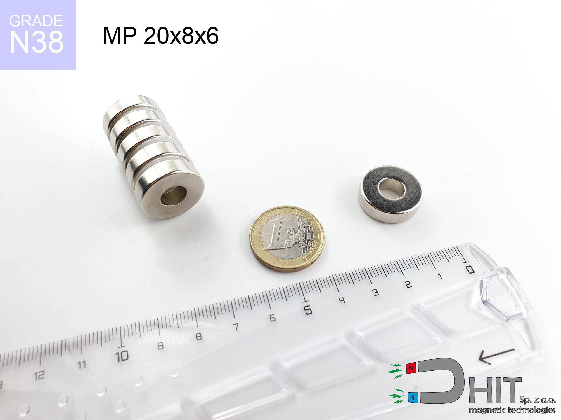
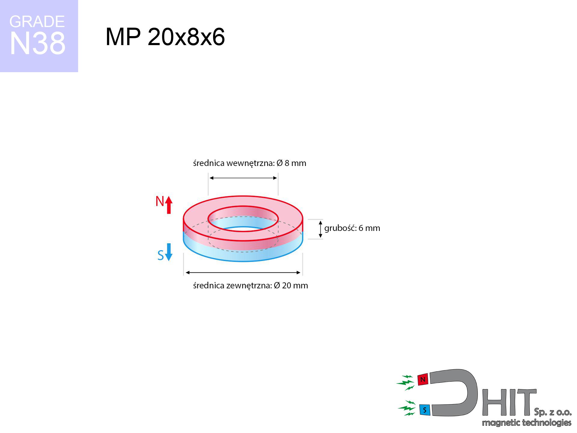
MP 20x8x6 / N38 - ring magnet
ring magnet
Catalog no 030189
GTIN/EAN: 5906301812067
Diameter
20 mm [±0,1 mm]
internal diameter Ø
8 mm [±0,1 mm]
Height
6 mm [±0,1 mm]
Weight
11.88 g
Magnetization Direction
↑ axial
Load capacity
7.22 kg / 70.81 N
Magnetic Induction
318.85 mT / 3188 Gs
Coating
[NiCuNi] Nickel
5.17 ZŁ with VAT / pcs + price for transport
4.20 ZŁ net + 23% VAT / pcs
bulk discounts:
Need more?
Call us
+48 22 499 98 98
if you prefer contact us through
form
our website.
Lifting power along with structure of a magnet can be calculated with our
force calculator.
Same-day processing for orders placed before 14:00.
Physical properties - MP 20x8x6 / N38 - ring magnet
Specification / characteristics - MP 20x8x6 / N38 - ring magnet
| properties | values |
|---|---|
| Cat. no. | 030189 |
| GTIN/EAN | 5906301812067 |
| Production/Distribution | Dhit sp. z o.o. |
| Country of origin | Poland / China / Germany |
| Customs code | 85059029 |
| Diameter | 20 mm [±0,1 mm] |
| internal diameter Ø | 8 mm [±0,1 mm] |
| Height | 6 mm [±0,1 mm] |
| Weight | 11.88 g |
| Magnetization Direction | ↑ axial |
| Load capacity ~ ? | 7.22 kg / 70.81 N |
| Magnetic Induction ~ ? | 318.85 mT / 3188 Gs |
| Coating | [NiCuNi] Nickel |
| Manufacturing Tolerance | ±0.1 mm |
Magnetic properties of material N38
| properties | values | units |
|---|---|---|
| remenance Br [min. - max.] ? | 12.2-12.6 | kGs |
| remenance Br [min. - max.] ? | 1220-1260 | mT |
| coercivity bHc ? | 10.8-11.5 | kOe |
| coercivity bHc ? | 860-915 | kA/m |
| actual internal force iHc | ≥ 12 | kOe |
| actual internal force iHc | ≥ 955 | kA/m |
| energy density [min. - max.] ? | 36-38 | BH max MGOe |
| energy density [min. - max.] ? | 287-303 | BH max KJ/m |
| max. temperature ? | ≤ 80 | °C |
Physical properties of sintered neodymium magnets Nd2Fe14B at 20°C
| properties | values | units |
|---|---|---|
| Vickers hardness | ≥550 | Hv |
| Density | ≥7.4 | g/cm3 |
| Curie Temperature TC | 312 - 380 | °C |
| Curie Temperature TF | 593 - 716 | °F |
| Specific resistance | 150 | μΩ⋅cm |
| Bending strength | 250 | MPa |
| Compressive strength | 1000~1100 | MPa |
| Thermal expansion parallel (∥) to orientation (M) | (3-4) x 10-6 | °C-1 |
| Thermal expansion perpendicular (⊥) to orientation (M) | -(1-3) x 10-6 | °C-1 |
| Young's modulus | 1.7 x 10⁴ | kg/mm² |
Technical simulation of the product - report
The following information constitute the outcome of a engineering calculation. Results are based on algorithms for the class Nd2Fe14B. Real-world performance may differ. Please consider these calculations as a reference point for designers.
Table 1: Static pull force (force vs distance) - characteristics
MP 20x8x6 / N38
| Distance (mm) | Induction (Gauss) / mT | Pull Force (kg/lbs/g/N) | Risk Status |
|---|---|---|---|
| 0 mm |
5917 Gs
591.7 mT
|
7.22 kg / 15.92 lbs
7220.0 g / 70.8 N
|
strong |
| 1 mm |
5321 Gs
532.1 mT
|
5.84 kg / 12.87 lbs
5839.8 g / 57.3 N
|
strong |
| 2 mm |
4736 Gs
473.6 mT
|
4.63 kg / 10.20 lbs
4626.6 g / 45.4 N
|
strong |
| 3 mm |
4184 Gs
418.4 mT
|
3.61 kg / 7.96 lbs
3610.0 g / 35.4 N
|
strong |
| 5 mm |
3216 Gs
321.6 mT
|
2.13 kg / 4.70 lbs
2132.9 g / 20.9 N
|
strong |
| 10 mm |
1650 Gs
165.0 mT
|
0.56 kg / 1.24 lbs
561.3 g / 5.5 N
|
low risk |
| 15 mm |
907 Gs
90.7 mT
|
0.17 kg / 0.37 lbs
169.7 g / 1.7 N
|
low risk |
| 20 mm |
544 Gs
54.4 mT
|
0.06 kg / 0.13 lbs
61.1 g / 0.6 N
|
low risk |
| 30 mm |
240 Gs
24.0 mT
|
0.01 kg / 0.03 lbs
11.9 g / 0.1 N
|
low risk |
| 50 mm |
75 Gs
7.5 mT
|
0.00 kg / 0.00 lbs
1.2 g / 0.0 N
|
low risk |
Table 2: Sliding load (wall)
MP 20x8x6 / N38
| Distance (mm) | Friction coefficient | Pull Force (kg/lbs/g/N) |
|---|---|---|
| 0 mm | Stal (~0.2) |
1.44 kg / 3.18 lbs
1444.0 g / 14.2 N
|
| 1 mm | Stal (~0.2) |
1.17 kg / 2.57 lbs
1168.0 g / 11.5 N
|
| 2 mm | Stal (~0.2) |
0.93 kg / 2.04 lbs
926.0 g / 9.1 N
|
| 3 mm | Stal (~0.2) |
0.72 kg / 1.59 lbs
722.0 g / 7.1 N
|
| 5 mm | Stal (~0.2) |
0.43 kg / 0.94 lbs
426.0 g / 4.2 N
|
| 10 mm | Stal (~0.2) |
0.11 kg / 0.25 lbs
112.0 g / 1.1 N
|
| 15 mm | Stal (~0.2) |
0.03 kg / 0.07 lbs
34.0 g / 0.3 N
|
| 20 mm | Stal (~0.2) |
0.01 kg / 0.03 lbs
12.0 g / 0.1 N
|
| 30 mm | Stal (~0.2) |
0.00 kg / 0.00 lbs
2.0 g / 0.0 N
|
| 50 mm | Stal (~0.2) |
0.00 kg / 0.00 lbs
0.0 g / 0.0 N
|
Table 3: Vertical assembly (sliding) - behavior on slippery surfaces
MP 20x8x6 / N38
| Surface type | Friction coefficient / % Mocy | Max load (kg/lbs/g/N) |
|---|---|---|
| Raw steel |
µ = 0.3
30% Nominalnej Siły
|
2.17 kg / 4.78 lbs
2166.0 g / 21.2 N
|
| Painted steel (standard) |
µ = 0.2
20% Nominalnej Siły
|
1.44 kg / 3.18 lbs
1444.0 g / 14.2 N
|
| Oily/slippery steel |
µ = 0.1
10% Nominalnej Siły
|
0.72 kg / 1.59 lbs
722.0 g / 7.1 N
|
| Magnet with anti-slip rubber |
µ = 0.5
50% Nominalnej Siły
|
3.61 kg / 7.96 lbs
3610.0 g / 35.4 N
|
Table 4: Material efficiency (saturation) - sheet metal selection
MP 20x8x6 / N38
| Steel thickness (mm) | % power | Real pull force (kg/lbs/g/N) |
|---|---|---|
| 0.5 mm |
|
0.72 kg / 1.59 lbs
722.0 g / 7.1 N
|
| 1 mm |
|
1.81 kg / 3.98 lbs
1805.0 g / 17.7 N
|
| 2 mm |
|
3.61 kg / 7.96 lbs
3610.0 g / 35.4 N
|
| 3 mm |
|
5.42 kg / 11.94 lbs
5415.0 g / 53.1 N
|
| 5 mm |
|
7.22 kg / 15.92 lbs
7220.0 g / 70.8 N
|
| 10 mm |
|
7.22 kg / 15.92 lbs
7220.0 g / 70.8 N
|
| 11 mm |
|
7.22 kg / 15.92 lbs
7220.0 g / 70.8 N
|
| 12 mm |
|
7.22 kg / 15.92 lbs
7220.0 g / 70.8 N
|
Table 5: Thermal resistance (material behavior) - power drop
MP 20x8x6 / N38
| Ambient temp. (°C) | Power loss | Remaining pull (kg/lbs/g/N) | Status |
|---|---|---|---|
| 20 °C | 0.0% |
7.22 kg / 15.92 lbs
7220.0 g / 70.8 N
|
OK |
| 40 °C | -2.2% |
7.06 kg / 15.57 lbs
7061.2 g / 69.3 N
|
OK |
| 60 °C | -4.4% |
6.90 kg / 15.22 lbs
6902.3 g / 67.7 N
|
OK |
| 80 °C | -6.6% |
6.74 kg / 14.87 lbs
6743.5 g / 66.2 N
|
|
| 100 °C | -28.8% |
5.14 kg / 11.33 lbs
5140.6 g / 50.4 N
|
Table 6: Two magnets (repulsion) - field collision
MP 20x8x6 / N38
| Gap (mm) | Attraction (kg/lbs) (N-S) | Sliding Force (kg/lbs/g/N) | Repulsion (kg/lbs) (N-N) |
|---|---|---|---|
| 0 mm |
52.44 kg / 115.62 lbs
6 121 Gs
|
7.87 kg / 17.34 lbs
7867 g / 77.2 N
|
N/A |
| 1 mm |
47.33 kg / 104.35 lbs
11 242 Gs
|
7.10 kg / 15.65 lbs
7100 g / 69.6 N
|
42.60 kg / 93.91 lbs
~0 Gs
|
| 2 mm |
42.42 kg / 93.52 lbs
10 642 Gs
|
6.36 kg / 14.03 lbs
6363 g / 62.4 N
|
38.18 kg / 84.16 lbs
~0 Gs
|
| 3 mm |
37.84 kg / 83.42 lbs
10 051 Gs
|
5.68 kg / 12.51 lbs
5675 g / 55.7 N
|
34.05 kg / 75.07 lbs
~0 Gs
|
| 5 mm |
29.73 kg / 65.55 lbs
8 910 Gs
|
4.46 kg / 9.83 lbs
4460 g / 43.8 N
|
26.76 kg / 59.00 lbs
~0 Gs
|
| 10 mm |
15.49 kg / 34.16 lbs
6 432 Gs
|
2.32 kg / 5.12 lbs
2324 g / 22.8 N
|
13.94 kg / 30.74 lbs
~0 Gs
|
| 20 mm |
4.08 kg / 8.99 lbs
3 299 Gs
|
0.61 kg / 1.35 lbs
612 g / 6.0 N
|
3.67 kg / 8.09 lbs
~0 Gs
|
| 50 mm |
0.18 kg / 0.41 lbs
702 Gs
|
0.03 kg / 0.06 lbs
28 g / 0.3 N
|
0.17 kg / 0.37 lbs
~0 Gs
|
| 60 mm |
0.09 kg / 0.19 lbs
480 Gs
|
0.01 kg / 0.03 lbs
13 g / 0.1 N
|
0.08 kg / 0.17 lbs
~0 Gs
|
| 70 mm |
0.04 kg / 0.10 lbs
342 Gs
|
0.01 kg / 0.01 lbs
7 g / 0.1 N
|
0.04 kg / 0.09 lbs
~0 Gs
|
| 80 mm |
0.02 kg / 0.05 lbs
253 Gs
|
0.00 kg / 0.01 lbs
4 g / 0.0 N
|
0.02 kg / 0.05 lbs
~0 Gs
|
| 90 mm |
0.01 kg / 0.03 lbs
193 Gs
|
0.00 kg / 0.00 lbs
2 g / 0.0 N
|
0.01 kg / 0.03 lbs
~0 Gs
|
| 100 mm |
0.01 kg / 0.02 lbs
150 Gs
|
0.00 kg / 0.00 lbs
1 g / 0.0 N
|
0.00 kg / 0.00 lbs
~0 Gs
|
Table 7: Safety (HSE) (electronics) - warnings
MP 20x8x6 / N38
| Object / Device | Limit (Gauss) / mT | Safe distance |
|---|---|---|
| Pacemaker | 5 Gs (0.5 mT) | 14.5 cm |
| Hearing aid | 10 Gs (1.0 mT) | 11.5 cm |
| Mechanical watch | 20 Gs (2.0 mT) | 9.0 cm |
| Mobile device | 40 Gs (4.0 mT) | 6.5 cm |
| Remote | 50 Gs (5.0 mT) | 6.0 cm |
| Payment card | 400 Gs (40.0 mT) | 2.5 cm |
| HDD hard drive | 600 Gs (60.0 mT) | 2.0 cm |
Table 8: Dynamics (cracking risk) - collision effects
MP 20x8x6 / N38
| Start from (mm) | Speed (km/h) | Energy (J) | Predicted outcome |
|---|---|---|---|
| 10 mm |
26.04 km/h
(7.23 m/s)
|
0.31 J | |
| 30 mm |
43.11 km/h
(11.97 m/s)
|
0.85 J | |
| 50 mm |
55.60 km/h
(15.44 m/s)
|
1.42 J | |
| 100 mm |
78.62 km/h
(21.84 m/s)
|
2.83 J |
Table 9: Surface protection spec
MP 20x8x6 / N38
| Technical parameter | Value / Description |
|---|---|
| Coating type | [NiCuNi] Nickel |
| Layer structure | Nickel - Copper - Nickel |
| Layer thickness | 10-20 µm |
| Salt spray test (SST) ? | 24 h |
| Recommended environment | Indoors only (dry) |
Table 10: Electrical data (Pc)
MP 20x8x6 / N38
| Parameter | Value | SI Unit / Description |
|---|---|---|
| Magnetic Flux | 15 688 Mx | 156.9 µWb |
| Pc Coefficient | 1.14 | High (Stable) |
Table 11: Physics of underwater searching
MP 20x8x6 / N38
| Environment | Effective steel pull | Effect |
|---|---|---|
| Air (land) | 7.22 kg | Standard |
| Water (riverbed) |
8.27 kg
(+1.05 kg buoyancy gain)
|
+14.5% |
1. Sliding resistance
*Caution: On a vertical surface, the magnet retains only ~20% of its perpendicular strength.
2. Plate thickness effect
*Thin metal sheet (e.g. 0.5mm PC case) drastically limits the holding force.
3. Thermal stability
*For standard magnets, the max working temp is 80°C.
4. Demagnetization curve and operating point (B-H)
chart generated for the permeance coefficient Pc (Permeance Coefficient) = 1.14
The chart above illustrates the magnetic characteristics of the material within the second quadrant of the hysteresis loop. The solid red line represents the demagnetization curve (material potential), while the dashed blue line is the load line based on the magnet's geometry. The Pc (Permeance Coefficient), also known as the load line slope, is a dimensionless value that describes the relationship between the magnet's shape and its magnetic stability. The intersection of these two lines (the black dot) is the operating point — it determines the actual magnetic flux density generated by the magnet in this specific configuration. A higher Pc value means the magnet is more 'slender' (tall relative to its area), resulting in a higher operating point and better resistance to irreversible demagnetization caused by external fields or temperature. A value of 0.42 is relatively low (typical for flat magnets), meaning the operating point is closer to the 'knee' of the curve — caution is advised when operating at temperatures near the maximum limit to avoid strength loss.
Chemical composition
| iron (Fe) | 64% – 68% |
| neodymium (Nd) | 29% – 32% |
| boron (B) | 1.1% – 1.2% |
| dysprosium (Dy) | 0.5% – 2.0% |
| coating (Ni-Cu-Ni) | < 0.05% |
Environmental data
| recyclability (EoL) | 100% |
| recycled raw materials | ~10% (pre-cons) |
| carbon footprint | low / zredukowany |
| waste code (EWC) | 16 02 16 |
Other offers


![SM 32x200 [2xM8] / N52 - magnetic separator](https://cdn3.dhit.pl/graphics/products/sm-32x200-2xm8-tus.jpg "SM 32x200 [2xM8] / N52 - magnetic separator")

Advantages and disadvantages of Nd2Fe14B magnets.
Benefits
- They have stable power, and over more than 10 years their performance decreases symbolically – ~1% (in testing),
- They have excellent resistance to magnetic field loss when exposed to opposing magnetic fields,
- Thanks to the shiny finish, the layer of nickel, gold-plated, or silver-plated gives an visually attractive appearance,
- The surface of neodymium magnets generates a unique magnetic field – this is a key feature,
- Made from properly selected components, these magnets show impressive resistance to high heat, enabling them to function (depending on their shape) at temperatures up to 230°C and above...
- Thanks to modularity in shaping and the capacity to customize to complex applications,
- Significant place in future technologies – they are commonly used in data components, electromotive mechanisms, advanced medical instruments, and modern systems.
- Relatively small size with high pulling force – neodymium magnets offer impressive pulling force in tiny dimensions, which makes them useful in miniature devices
Weaknesses
- At strong impacts they can break, therefore we advise placing them in steel cases. A metal housing provides additional protection against damage and increases the magnet's durability.
- NdFeB magnets demagnetize when exposed to high temperatures. After reaching 80°C, many of them experience permanent drop of strength (a factor is the shape and dimensions of the magnet). We offer magnets specially adapted to work at temperatures up to 230°C marked [AH], which are very resistant to heat
- When exposed to humidity, magnets usually rust. For applications outside, it is recommended to use protective magnets, such as magnets in rubber or plastics, which prevent oxidation as well as corrosion.
- We recommend casing - magnetic mechanism, due to difficulties in realizing nuts inside the magnet and complex forms.
- Possible danger resulting from small fragments of magnets can be dangerous, when accidentally swallowed, which becomes key in the context of child health protection. Additionally, tiny parts of these magnets can disrupt the diagnostic process medical in case of swallowing.
- With mass production the cost of neodymium magnets can be a barrier,
Lifting parameters
Maximum holding power of the magnet – what it depends on?
- using a sheet made of high-permeability steel, serving as a circuit closing element
- with a thickness of at least 10 mm
- with an polished contact surface
- with direct contact (no impurities)
- for force applied at a right angle (pull-off, not shear)
- in stable room temperature
Determinants of lifting force in real conditions
- Space between magnet and steel – even a fraction of a millimeter of distance (caused e.g. by veneer or dirt) significantly weakens the magnet efficiency, often by half at just 0.5 mm.
- Direction of force – highest force is obtained only during pulling at a 90° angle. The force required to slide of the magnet along the surface is usually several times lower (approx. 1/5 of the lifting capacity).
- Base massiveness – too thin sheet does not close the flux, causing part of the power to be lost to the other side.
- Material type – ideal substrate is pure iron steel. Hardened steels may have worse magnetic properties.
- Surface finish – ideal contact is obtained only on polished steel. Rough texture reduce the real contact area, weakening the magnet.
- Thermal conditions – neodymium magnets have a negative temperature coefficient. At higher temperatures they are weaker, and at low temperatures gain strength (up to a certain limit).
Lifting capacity testing was performed on plates with a smooth surface of optimal thickness, under a perpendicular pulling force, in contrast under attempts to slide the magnet the lifting capacity is smaller. In addition, even a slight gap between the magnet’s surface and the plate reduces the holding force.
Precautions when working with NdFeB magnets
Machining danger
Combustion risk: Rare earth powder is highly flammable. Do not process magnets in home conditions as this may cause fire.
Magnetic interference
Note: neodymium magnets produce a field that disrupts precision electronics. Maintain a safe distance from your mobile, tablet, and navigation systems.
Conscious usage
Before use, read the rules. Uncontrolled attraction can destroy the magnet or hurt your hand. Think ahead.
Product not for children
Product intended for adults. Tiny parts can be swallowed, leading to severe trauma. Keep away from children and animals.
Allergy Warning
Nickel alert: The nickel-copper-nickel coating contains nickel. If redness happens, cease working with magnets and use protective gear.
Health Danger
People with a ICD should keep an safe separation from magnets. The magnetic field can stop the functioning of the implant.
Material brittleness
Beware of splinters. Magnets can explode upon violent connection, launching shards into the air. Wear goggles.
Data carriers
Avoid bringing magnets close to a wallet, computer, or TV. The magnetic field can permanently damage these devices and erase data from cards.
Bone fractures
Big blocks can smash fingers in a fraction of a second. Under no circumstances place your hand between two attracting surfaces.
Heat sensitivity
Monitor thermal conditions. Heating the magnet above 80 degrees Celsius will ruin its magnetic structure and strength.
Tabela kosztu i czasu dostawy
Płatność przed wysyłką:

GLS kurier
Przesyłka będzie u Ciebie za 2-3 dni
14.99 ZŁ

InPost Paczkomaty 24/7
Przesyłka będzie u Ciebie za 1-2 dni
12.30 ZŁ
Płatność przy odbiorze (pobranie):
GLS kurier
Przesyłka będzie u Ciebie za 1-2 dni
23.00 ZŁ
Rate the product
Your rating