
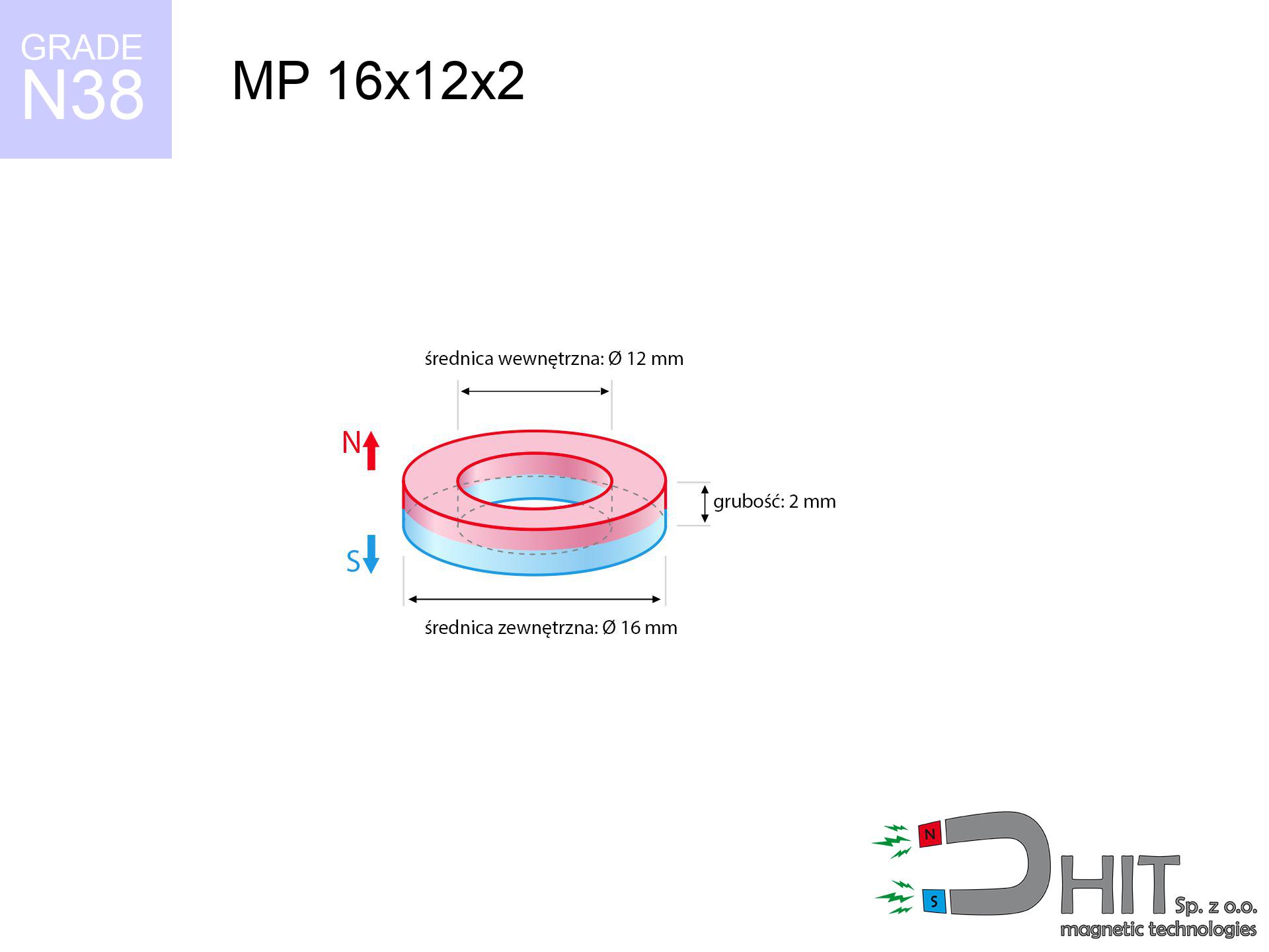
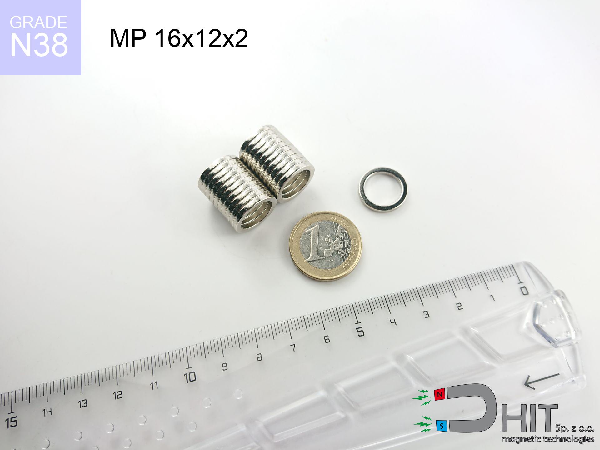
MP 16x12x2 / N38 - ring magnet
ring magnet
Catalog no 030183
GTIN/EAN: 5906301812005
Diameter
16 mm [±0,1 mm]
internal diameter Ø
12 mm [±0,1 mm]
Height
2 mm [±0,1 mm]
Weight
1.32 g
Magnetization Direction
↑ axial
Load capacity
0.68 kg / 6.62 N
Magnetic Induction
150.33 mT / 1503 Gs
Coating
[NiCuNi] Nickel
1.304 ZŁ with VAT / pcs + price for transport
1.060 ZŁ net + 23% VAT / pcs
bulk discounts:
Need more?
Call us
+48 888 99 98 98
alternatively let us know using
contact form
the contact page.
Weight along with appearance of magnets can be verified with our
magnetic calculator.
Same-day processing for orders placed before 14:00.
Detailed specification - MP 16x12x2 / N38 - ring magnet
Specification / characteristics - MP 16x12x2 / N38 - ring magnet
| properties | values |
|---|---|
| Cat. no. | 030183 |
| GTIN/EAN | 5906301812005 |
| Production/Distribution | Dhit sp. z o.o. |
| Country of origin | Poland / China / Germany |
| Customs code | 85059029 |
| Diameter | 16 mm [±0,1 mm] |
| internal diameter Ø | 12 mm [±0,1 mm] |
| Height | 2 mm [±0,1 mm] |
| Weight | 1.32 g |
| Magnetization Direction | ↑ axial |
| Load capacity ~ ? | 0.68 kg / 6.62 N |
| Magnetic Induction ~ ? | 150.33 mT / 1503 Gs |
| Coating | [NiCuNi] Nickel |
| Manufacturing Tolerance | ±0.1 mm |
Magnetic properties of material N38
| properties | values | units |
|---|---|---|
| remenance Br [min. - max.] ? | 12.2-12.6 | kGs |
| remenance Br [min. - max.] ? | 1220-1260 | mT |
| coercivity bHc ? | 10.8-11.5 | kOe |
| coercivity bHc ? | 860-915 | kA/m |
| actual internal force iHc | ≥ 12 | kOe |
| actual internal force iHc | ≥ 955 | kA/m |
| energy density [min. - max.] ? | 36-38 | BH max MGOe |
| energy density [min. - max.] ? | 287-303 | BH max KJ/m |
| max. temperature ? | ≤ 80 | °C |
Physical properties of sintered neodymium magnets Nd2Fe14B at 20°C
| properties | values | units |
|---|---|---|
| Vickers hardness | ≥550 | Hv |
| Density | ≥7.4 | g/cm3 |
| Curie Temperature TC | 312 - 380 | °C |
| Curie Temperature TF | 593 - 716 | °F |
| Specific resistance | 150 | μΩ⋅cm |
| Bending strength | 250 | MPa |
| Compressive strength | 1000~1100 | MPa |
| Thermal expansion parallel (∥) to orientation (M) | (3-4) x 10-6 | °C-1 |
| Thermal expansion perpendicular (⊥) to orientation (M) | -(1-3) x 10-6 | °C-1 |
| Young's modulus | 1.7 x 10⁴ | kg/mm² |
Technical analysis of the assembly - data
These information are the direct effect of a mathematical analysis. Results are based on algorithms for the class Nd2Fe14B. Real-world parameters might slightly differ from theoretical values. Please consider these calculations as a preliminary roadmap for designers.
Table 1: Static pull force (force vs distance) - interaction chart
MP 16x12x2 / N38
| Distance (mm) | Induction (Gauss) / mT | Pull Force (kg/lbs/g/N) | Risk Status |
|---|---|---|---|
| 0 mm |
6011 Gs
601.1 mT
|
0.68 kg / 1.50 pounds
680.0 g / 6.7 N
|
weak grip |
| 1 mm |
5259 Gs
525.9 mT
|
0.52 kg / 1.15 pounds
520.7 g / 5.1 N
|
weak grip |
| 2 mm |
4534 Gs
453.4 mT
|
0.39 kg / 0.85 pounds
387.0 g / 3.8 N
|
weak grip |
| 3 mm |
3870 Gs
387.0 mT
|
0.28 kg / 0.62 pounds
281.9 g / 2.8 N
|
weak grip |
| 5 mm |
2776 Gs
277.6 mT
|
0.15 kg / 0.32 pounds
145.1 g / 1.4 N
|
weak grip |
| 10 mm |
1251 Gs
125.1 mT
|
0.03 kg / 0.06 pounds
29.4 g / 0.3 N
|
weak grip |
| 15 mm |
643 Gs
64.3 mT
|
0.01 kg / 0.02 pounds
7.8 g / 0.1 N
|
weak grip |
| 20 mm |
372 Gs
37.2 mT
|
0.00 kg / 0.01 pounds
2.6 g / 0.0 N
|
weak grip |
| 30 mm |
159 Gs
15.9 mT
|
0.00 kg / 0.00 pounds
0.5 g / 0.0 N
|
weak grip |
| 50 mm |
49 Gs
4.9 mT
|
0.00 kg / 0.00 pounds
0.0 g / 0.0 N
|
weak grip |
Table 2: Sliding load (vertical surface)
MP 16x12x2 / N38
| Distance (mm) | Friction coefficient | Pull Force (kg/lbs/g/N) |
|---|---|---|
| 0 mm | Stal (~0.2) |
0.14 kg / 0.30 pounds
136.0 g / 1.3 N
|
| 1 mm | Stal (~0.2) |
0.10 kg / 0.23 pounds
104.0 g / 1.0 N
|
| 2 mm | Stal (~0.2) |
0.08 kg / 0.17 pounds
78.0 g / 0.8 N
|
| 3 mm | Stal (~0.2) |
0.06 kg / 0.12 pounds
56.0 g / 0.5 N
|
| 5 mm | Stal (~0.2) |
0.03 kg / 0.07 pounds
30.0 g / 0.3 N
|
| 10 mm | Stal (~0.2) |
0.01 kg / 0.01 pounds
6.0 g / 0.1 N
|
| 15 mm | Stal (~0.2) |
0.00 kg / 0.00 pounds
2.0 g / 0.0 N
|
| 20 mm | Stal (~0.2) |
0.00 kg / 0.00 pounds
0.0 g / 0.0 N
|
| 30 mm | Stal (~0.2) |
0.00 kg / 0.00 pounds
0.0 g / 0.0 N
|
| 50 mm | Stal (~0.2) |
0.00 kg / 0.00 pounds
0.0 g / 0.0 N
|
Table 3: Vertical assembly (sliding) - vertical pull
MP 16x12x2 / N38
| Surface type | Friction coefficient / % Mocy | Max load (kg/lbs/g/N) |
|---|---|---|
| Raw steel |
µ = 0.3
30% Nominalnej Siły
|
0.20 kg / 0.45 pounds
204.0 g / 2.0 N
|
| Painted steel (standard) |
µ = 0.2
20% Nominalnej Siły
|
0.14 kg / 0.30 pounds
136.0 g / 1.3 N
|
| Oily/slippery steel |
µ = 0.1
10% Nominalnej Siły
|
0.07 kg / 0.15 pounds
68.0 g / 0.7 N
|
| Magnet with anti-slip rubber |
µ = 0.5
50% Nominalnej Siły
|
0.34 kg / 0.75 pounds
340.0 g / 3.3 N
|
Table 4: Steel thickness (saturation) - sheet metal selection
MP 16x12x2 / N38
| Steel thickness (mm) | % power | Real pull force (kg/lbs/g/N) |
|---|---|---|
| 0.5 mm |
|
0.07 kg / 0.15 pounds
68.0 g / 0.7 N
|
| 1 mm |
|
0.17 kg / 0.37 pounds
170.0 g / 1.7 N
|
| 2 mm |
|
0.34 kg / 0.75 pounds
340.0 g / 3.3 N
|
| 3 mm |
|
0.51 kg / 1.12 pounds
510.0 g / 5.0 N
|
| 5 mm |
|
0.68 kg / 1.50 pounds
680.0 g / 6.7 N
|
| 10 mm |
|
0.68 kg / 1.50 pounds
680.0 g / 6.7 N
|
| 11 mm |
|
0.68 kg / 1.50 pounds
680.0 g / 6.7 N
|
| 12 mm |
|
0.68 kg / 1.50 pounds
680.0 g / 6.7 N
|
Table 5: Thermal resistance (material behavior) - power drop
MP 16x12x2 / N38
| Ambient temp. (°C) | Power loss | Remaining pull (kg/lbs/g/N) | Status |
|---|---|---|---|
| 20 °C | 0.0% |
0.68 kg / 1.50 pounds
680.0 g / 6.7 N
|
OK |
| 40 °C | -2.2% |
0.67 kg / 1.47 pounds
665.0 g / 6.5 N
|
OK |
| 60 °C | -4.4% |
0.65 kg / 1.43 pounds
650.1 g / 6.4 N
|
OK |
| 80 °C | -6.6% |
0.64 kg / 1.40 pounds
635.1 g / 6.2 N
|
|
| 100 °C | -28.8% |
0.48 kg / 1.07 pounds
484.2 g / 4.7 N
|
Table 6: Magnet-Magnet interaction (attraction) - forces in the system
MP 16x12x2 / N38
| Gap (mm) | Attraction (kg/lbs) (N-S) | Sliding Force (kg/lbs/g/N) | Repulsion (kg/lbs) (N-N) |
|---|---|---|---|
| 0 mm |
37.47 kg / 82.60 pounds
6 145 Gs
|
5.62 kg / 12.39 pounds
5620 g / 55.1 N
|
N/A |
| 1 mm |
32.95 kg / 72.65 pounds
11 273 Gs
|
4.94 kg / 10.90 pounds
4943 g / 48.5 N
|
29.66 kg / 65.38 pounds
~0 Gs
|
| 2 mm |
28.69 kg / 63.25 pounds
10 519 Gs
|
4.30 kg / 9.49 pounds
4303 g / 42.2 N
|
25.82 kg / 56.92 pounds
~0 Gs
|
| 3 mm |
24.81 kg / 54.69 pounds
9 781 Gs
|
3.72 kg / 8.20 pounds
3721 g / 36.5 N
|
22.33 kg / 49.22 pounds
~0 Gs
|
| 5 mm |
18.24 kg / 40.20 pounds
8 386 Gs
|
2.74 kg / 6.03 pounds
2735 g / 26.8 N
|
16.41 kg / 36.18 pounds
~0 Gs
|
| 10 mm |
7.99 kg / 17.62 pounds
5 552 Gs
|
1.20 kg / 2.64 pounds
1199 g / 11.8 N
|
7.19 kg / 15.86 pounds
~0 Gs
|
| 20 mm |
1.62 kg / 3.58 pounds
2 501 Gs
|
0.24 kg / 0.54 pounds
243 g / 2.4 N
|
1.46 kg / 3.22 pounds
~0 Gs
|
| 50 mm |
0.06 kg / 0.13 pounds
471 Gs
|
0.01 kg / 0.02 pounds
9 g / 0.1 N
|
0.05 kg / 0.11 pounds
~0 Gs
|
| 60 mm |
0.03 kg / 0.06 pounds
318 Gs
|
0.00 kg / 0.01 pounds
4 g / 0.0 N
|
0.02 kg / 0.05 pounds
~0 Gs
|
| 70 mm |
0.01 kg / 0.03 pounds
225 Gs
|
0.00 kg / 0.00 pounds
2 g / 0.0 N
|
0.01 kg / 0.03 pounds
~0 Gs
|
| 80 mm |
0.01 kg / 0.02 pounds
166 Gs
|
0.00 kg / 0.00 pounds
1 g / 0.0 N
|
0.00 kg / 0.00 pounds
~0 Gs
|
| 90 mm |
0.00 kg / 0.01 pounds
126 Gs
|
0.00 kg / 0.00 pounds
1 g / 0.0 N
|
0.00 kg / 0.00 pounds
~0 Gs
|
| 100 mm |
0.00 kg / 0.01 pounds
98 Gs
|
0.00 kg / 0.00 pounds
0 g / 0.0 N
|
0.00 kg / 0.00 pounds
~0 Gs
|
Table 7: Hazards (electronics) - warnings
MP 16x12x2 / N38
| Object / Device | Limit (Gauss) / mT | Safe distance |
|---|---|---|
| Pacemaker | 5 Gs (0.5 mT) | 12.5 cm |
| Hearing aid | 10 Gs (1.0 mT) | 9.5 cm |
| Mechanical watch | 20 Gs (2.0 mT) | 7.5 cm |
| Mobile device | 40 Gs (4.0 mT) | 5.5 cm |
| Car key | 50 Gs (5.0 mT) | 5.0 cm |
| Payment card | 400 Gs (40.0 mT) | 2.0 cm |
| HDD hard drive | 600 Gs (60.0 mT) | 2.0 cm |
Table 8: Dynamics (cracking risk) - warning
MP 16x12x2 / N38
| Start from (mm) | Speed (km/h) | Energy (J) | Predicted outcome |
|---|---|---|---|
| 10 mm |
23.50 km/h
(6.53 m/s)
|
0.03 J | |
| 30 mm |
39.66 km/h
(11.02 m/s)
|
0.08 J | |
| 50 mm |
51.19 km/h
(14.22 m/s)
|
0.13 J | |
| 100 mm |
72.39 km/h
(20.11 m/s)
|
0.27 J |
Table 9: Surface protection spec
MP 16x12x2 / N38
| Technical parameter | Value / Description |
|---|---|
| Coating type | [NiCuNi] Nickel |
| Layer structure | Nickel - Copper - Nickel |
| Layer thickness | 10-20 µm |
| Salt spray test (SST) ? | 24 h |
| Recommended environment | Indoors only (dry) |
Table 10: Electrical data (Pc)
MP 16x12x2 / N38
| Parameter | Value | SI Unit / Description |
|---|---|---|
| Magnetic Flux | 11 219 Mx | 112.2 µWb |
| Pc Coefficient | 1.22 | High (Stable) |
Table 11: Submerged application
MP 16x12x2 / N38
| Environment | Effective steel pull | Effect |
|---|---|---|
| Air (land) | 0.68 kg | Standard |
| Water (riverbed) |
0.78 kg
(+0.10 kg buoyancy gain)
|
+14.5% |
1. Sliding resistance
*Caution: On a vertical surface, the magnet retains merely a fraction of its nominal pull.
2. Steel saturation
*Thin steel (e.g. computer case) drastically weakens the holding force.
3. Power loss vs temp
*For standard magnets, the critical limit is 80°C.
4. Demagnetization curve and operating point (B-H)
chart generated for the permeance coefficient Pc (Permeance Coefficient) = 1.22
The chart above illustrates the magnetic characteristics of the material within the second quadrant of the hysteresis loop. The solid red line represents the demagnetization curve (material potential), while the dashed blue line is the load line based on the magnet's geometry. The Pc (Permeance Coefficient), also known as the load line slope, is a dimensionless value that describes the relationship between the magnet's shape and its magnetic stability. The intersection of these two lines (the black dot) is the operating point — it determines the actual magnetic flux density generated by the magnet in this specific configuration. A higher Pc value means the magnet is more 'slender' (tall relative to its area), resulting in a higher operating point and better resistance to irreversible demagnetization caused by external fields or temperature. A value of 0.42 is relatively low (typical for flat magnets), meaning the operating point is closer to the 'knee' of the curve — caution is advised when operating at temperatures near the maximum limit to avoid strength loss.
Chemical composition
| iron (Fe) | 64% – 68% |
| neodymium (Nd) | 29% – 32% |
| boron (B) | 1.1% – 1.2% |
| dysprosium (Dy) | 0.5% – 2.0% |
| coating (Ni-Cu-Ni) | < 0.05% |
Environmental data
| recyclability (EoL) | 100% |
| recycled raw materials | ~10% (pre-cons) |
| carbon footprint | low / zredukowany |
| waste code (EWC) | 16 02 16 |
Other deals

![SM 25x375 [2xM8] / N42 - magnetic separator](https://cdn3.dhit.pl/graphics/products/sm-25x375-2xm8-feg.jpg "SM 25x375 [2xM8] / N42 - magnetic separator")


Strengths and weaknesses of rare earth magnets.
Benefits
- They do not lose magnetism, even after approximately 10 years – the reduction in strength is only ~1% (based on measurements),
- Neodymium magnets are characterized by remarkably resistant to loss of magnetic properties caused by external magnetic fields,
- Thanks to the smooth finish, the coating of nickel, gold, or silver-plated gives an visually attractive appearance,
- The surface of neodymium magnets generates a intense magnetic field – this is a key feature,
- Thanks to resistance to high temperature, they are able to function (depending on the shape) even at temperatures up to 230°C and higher...
- Thanks to the ability of flexible molding and customization to specialized solutions, neodymium magnets can be created in a broad palette of forms and dimensions, which makes them more universal,
- Significant place in future technologies – they find application in data components, drive modules, medical devices, and other advanced devices.
- Compactness – despite small sizes they generate large force, making them ideal for precision applications
Limitations
- They are prone to damage upon too strong impacts. To avoid cracks, it is worth protecting magnets in special housings. Such protection not only protects the magnet but also improves its resistance to damage
- When exposed to high temperature, neodymium magnets experience a drop in power. Often, when the temperature exceeds 80°C, their power decreases (depending on the size and shape of the magnet). For those who need magnets for extreme conditions, we offer [AH] versions withstanding up to 230°C
- Magnets exposed to a humid environment can corrode. Therefore when using outdoors, we suggest using waterproof magnets made of rubber, plastic or other material resistant to moisture
- We suggest cover - magnetic mechanism, due to difficulties in creating threads inside the magnet and complex forms.
- Potential hazard to health – tiny shards of magnets can be dangerous, if swallowed, which gains importance in the aspect of protecting the youngest. It is also worth noting that small elements of these magnets are able to be problematic in diagnostics medical after entering the body.
- High unit price – neodymium magnets have a higher price than other types of magnets (e.g. ferrite), which can limit application in large quantities
Pull force analysis
Maximum holding power of the magnet – what contributes to it?
- using a sheet made of low-carbon steel, acting as a magnetic yoke
- with a cross-section of at least 10 mm
- with an ideally smooth contact surface
- with direct contact (no paint)
- under axial force vector (90-degree angle)
- at temperature approx. 20 degrees Celsius
Determinants of practical lifting force of a magnet
- Air gap (betwixt the magnet and the plate), as even a very small distance (e.g. 0.5 mm) results in a reduction in lifting capacity by up to 50% (this also applies to paint, corrosion or debris).
- Loading method – declared lifting capacity refers to detachment vertically. When applying parallel force, the magnet holds much less (often approx. 20-30% of maximum force).
- Substrate thickness – for full efficiency, the steel must be sufficiently thick. Paper-thin metal limits the lifting capacity (the magnet "punches through" it).
- Steel type – low-carbon steel attracts best. Alloy steels decrease magnetic properties and holding force.
- Surface quality – the smoother and more polished the surface, the larger the contact zone and stronger the hold. Unevenness acts like micro-gaps.
- Thermal environment – temperature increase causes a temporary drop of induction. Check the maximum operating temperature for a given model.
Lifting capacity was determined by applying a steel plate with a smooth surface of optimal thickness (min. 20 mm), under vertically applied force, in contrast under parallel forces the holding force is lower. In addition, even a slight gap between the magnet’s surface and the plate lowers the holding force.
Safety rules for work with neodymium magnets
Swallowing risk
Always keep magnets out of reach of children. Risk of swallowing is high, and the effects of magnets clamping inside the body are life-threatening.
Flammability
Mechanical processing of neodymium magnets carries a risk of fire hazard. Neodymium dust reacts violently with oxygen and is difficult to extinguish.
Threat to electronics
Intense magnetic fields can corrupt files on credit cards, hard drives, and other magnetic media. Stay away of at least 10 cm.
Shattering risk
Beware of splinters. Magnets can fracture upon violent connection, ejecting shards into the air. Eye protection is mandatory.
Precision electronics
Note: neodymium magnets generate a field that confuses precision electronics. Keep a safe distance from your phone, tablet, and GPS.
Physical harm
Pinching hazard: The attraction force is so immense that it can result in blood blisters, crushing, and even bone fractures. Use thick gloves.
Health Danger
Medical warning: Neodymium magnets can turn off heart devices and defibrillators. Stay away if you have medical devices.
Permanent damage
Regular neodymium magnets (N-type) lose power when the temperature surpasses 80°C. Damage is permanent.
Sensitization to coating
Studies show that nickel (the usual finish) is a common allergen. If your skin reacts to metals, refrain from touching magnets with bare hands or select versions in plastic housing.
Caution required
Exercise caution. Neodymium magnets act from a long distance and connect with massive power, often quicker than you can react.
Tabela kosztu i czasu dostawy
Płatność przed wysyłką:

GLS kurier
Przesyłka będzie u Ciebie za 2-3 dni
14.99 ZŁ

InPost Paczkomaty 24/7
Przesyłka będzie u Ciebie za 1-2 dni
12.30 ZŁ
Płatność przy odbiorze (pobranie):
GLS kurier
Przesyłka będzie u Ciebie za 1-2 dni
23.00 ZŁ
Rate the product
Your rating