
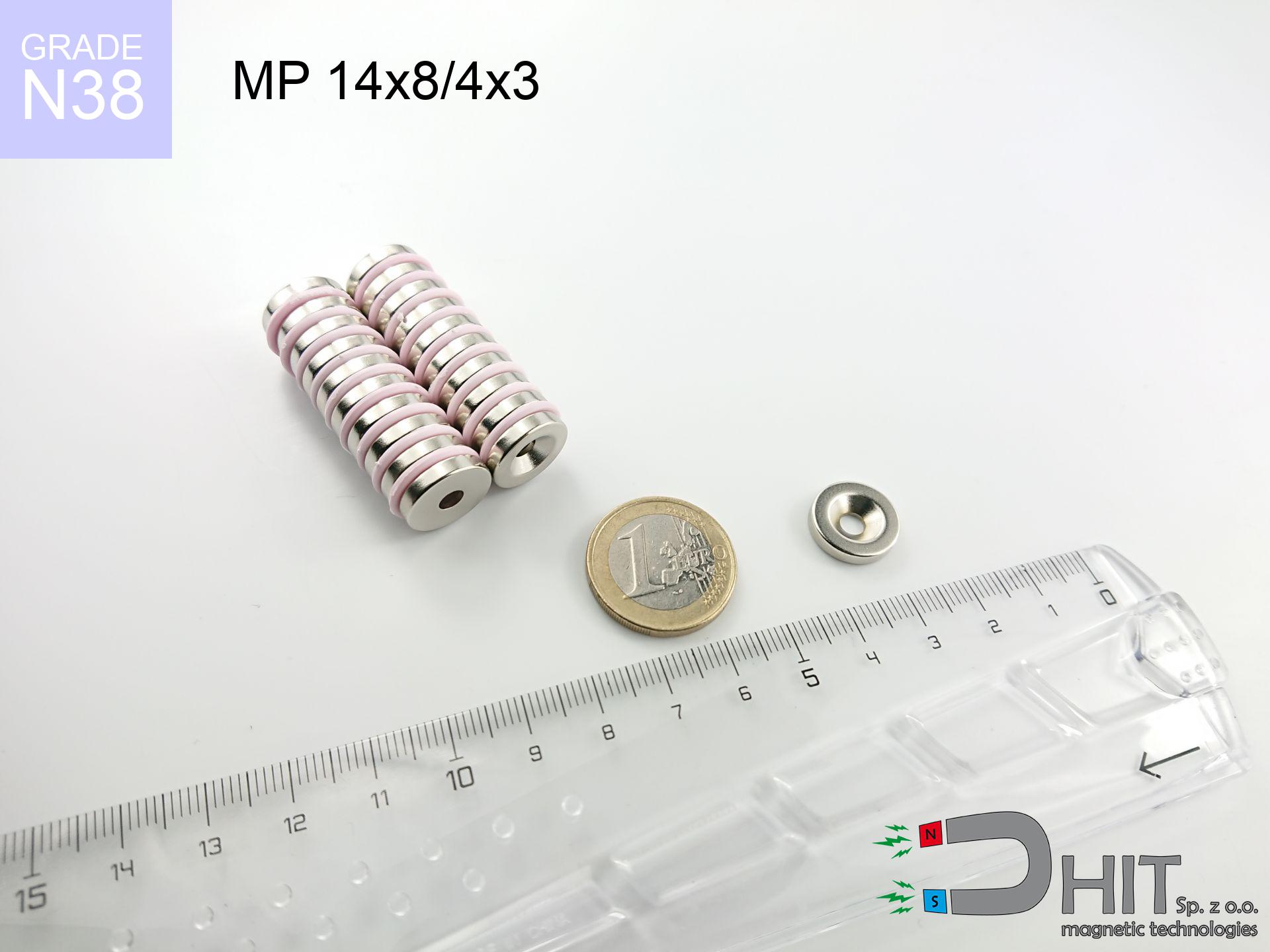
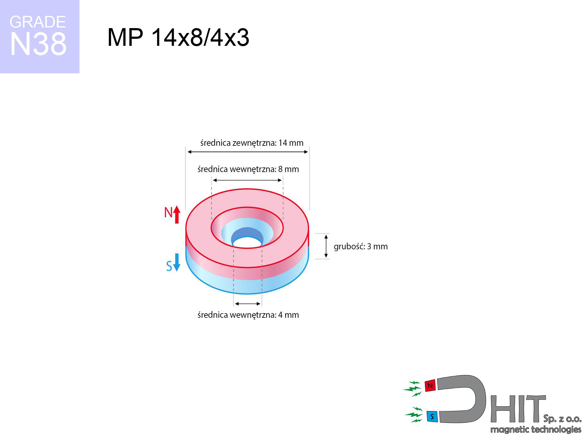
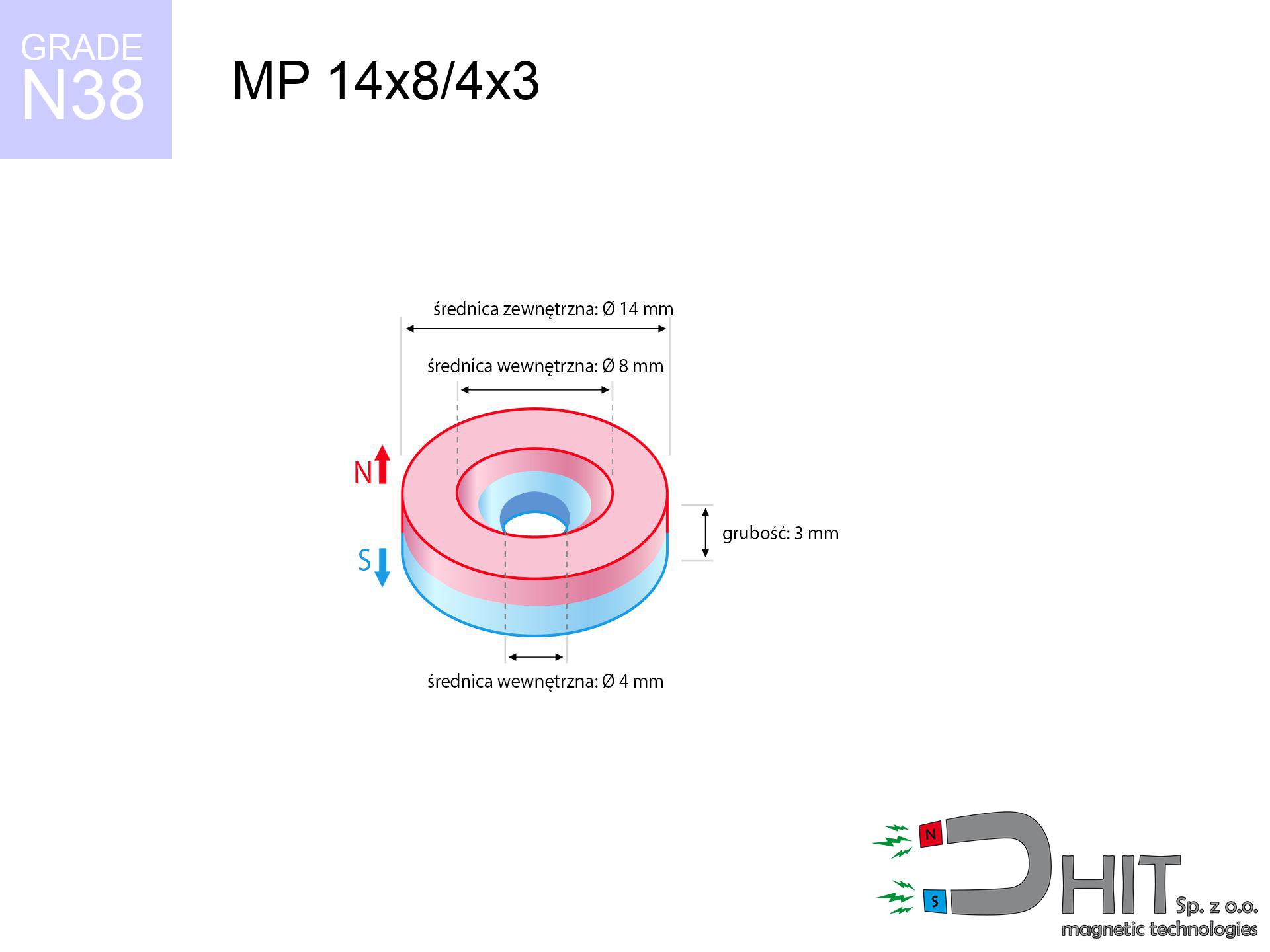
MP 14x8/4x3 / N38 - ring magnet
ring magnet
Catalog no 030181
GTIN/EAN: 5906301811985
Diameter
14 mm [±0,1 mm]
internal diameter Ø
8/4 mm [±0,1 mm]
Height
3 mm [±0,1 mm]
Weight
3.18 g
Magnetization Direction
↑ axial
Load capacity
2.53 kg / 24.85 N
Magnetic Induction
244.11 mT / 2441 Gs
Coating
[NiCuNi] Nickel
2.47 ZŁ with VAT / pcs + price for transport
2.01 ZŁ net + 23% VAT / pcs
bulk discounts:
Need more?
Call us now
+48 22 499 98 98
alternatively contact us via
request form
the contact form page.
Weight along with form of magnets can be analyzed on our
magnetic mass calculator.
Orders submitted before 14:00 will be dispatched today!
Detailed specification - MP 14x8/4x3 / N38 - ring magnet
Specification / characteristics - MP 14x8/4x3 / N38 - ring magnet
| properties | values |
|---|---|
| Cat. no. | 030181 |
| GTIN/EAN | 5906301811985 |
| Production/Distribution | Dhit sp. z o.o. |
| Country of origin | Poland / China / Germany |
| Customs code | 85059029 |
| Diameter | 14 mm [±0,1 mm] |
| internal diameter Ø | 8/4 mm [±0,1 mm] |
| Height | 3 mm [±0,1 mm] |
| Weight | 3.18 g |
| Magnetization Direction | ↑ axial |
| Load capacity ~ ? | 2.53 kg / 24.85 N |
| Magnetic Induction ~ ? | 244.11 mT / 2441 Gs |
| Coating | [NiCuNi] Nickel |
| Manufacturing Tolerance | ±0.1 mm |
Magnetic properties of material N38
| properties | values | units |
|---|---|---|
| remenance Br [min. - max.] ? | 12.2-12.6 | kGs |
| remenance Br [min. - max.] ? | 1220-1260 | mT |
| coercivity bHc ? | 10.8-11.5 | kOe |
| coercivity bHc ? | 860-915 | kA/m |
| actual internal force iHc | ≥ 12 | kOe |
| actual internal force iHc | ≥ 955 | kA/m |
| energy density [min. - max.] ? | 36-38 | BH max MGOe |
| energy density [min. - max.] ? | 287-303 | BH max KJ/m |
| max. temperature ? | ≤ 80 | °C |
Physical properties of sintered neodymium magnets Nd2Fe14B at 20°C
| properties | values | units |
|---|---|---|
| Vickers hardness | ≥550 | Hv |
| Density | ≥7.4 | g/cm3 |
| Curie Temperature TC | 312 - 380 | °C |
| Curie Temperature TF | 593 - 716 | °F |
| Specific resistance | 150 | μΩ⋅cm |
| Bending strength | 250 | MPa |
| Compressive strength | 1000~1100 | MPa |
| Thermal expansion parallel (∥) to orientation (M) | (3-4) x 10-6 | °C-1 |
| Thermal expansion perpendicular (⊥) to orientation (M) | -(1-3) x 10-6 | °C-1 |
| Young's modulus | 1.7 x 10⁴ | kg/mm² |
Engineering analysis of the assembly - technical parameters
Presented values are the outcome of a physical analysis. Results rely on models for the material Nd2Fe14B. Real-world parameters might slightly differ. Use these calculations as a preliminary roadmap for designers.
Table 1: Static force (force vs gap) - characteristics
MP 14x8/4x3 / N38
| Distance (mm) | Induction (Gauss) / mT | Pull Force (kg/lbs/g/N) | Risk Status |
|---|---|---|---|
| 0 mm |
2121 Gs
212.1 mT
|
2.53 kg / 5.58 pounds
2530.0 g / 24.8 N
|
strong |
| 1 mm |
1927 Gs
192.7 mT
|
2.09 kg / 4.61 pounds
2090.1 g / 20.5 N
|
strong |
| 2 mm |
1676 Gs
167.6 mT
|
1.58 kg / 3.48 pounds
1579.6 g / 15.5 N
|
weak grip |
| 3 mm |
1410 Gs
141.0 mT
|
1.12 kg / 2.46 pounds
1117.9 g / 11.0 N
|
weak grip |
| 5 mm |
943 Gs
94.3 mT
|
0.50 kg / 1.10 pounds
500.1 g / 4.9 N
|
weak grip |
| 10 mm |
335 Gs
33.5 mT
|
0.06 kg / 0.14 pounds
63.3 g / 0.6 N
|
weak grip |
| 15 mm |
140 Gs
14.0 mT
|
0.01 kg / 0.02 pounds
11.1 g / 0.1 N
|
weak grip |
| 20 mm |
69 Gs
6.9 mT
|
0.00 kg / 0.01 pounds
2.7 g / 0.0 N
|
weak grip |
| 30 mm |
24 Gs
2.4 mT
|
0.00 kg / 0.00 pounds
0.3 g / 0.0 N
|
weak grip |
| 50 mm |
6 Gs
0.6 mT
|
0.00 kg / 0.00 pounds
0.0 g / 0.0 N
|
weak grip |
Table 2: Shear hold (vertical surface)
MP 14x8/4x3 / N38
| Distance (mm) | Friction coefficient | Pull Force (kg/lbs/g/N) |
|---|---|---|
| 0 mm | Stal (~0.2) |
0.51 kg / 1.12 pounds
506.0 g / 5.0 N
|
| 1 mm | Stal (~0.2) |
0.42 kg / 0.92 pounds
418.0 g / 4.1 N
|
| 2 mm | Stal (~0.2) |
0.32 kg / 0.70 pounds
316.0 g / 3.1 N
|
| 3 mm | Stal (~0.2) |
0.22 kg / 0.49 pounds
224.0 g / 2.2 N
|
| 5 mm | Stal (~0.2) |
0.10 kg / 0.22 pounds
100.0 g / 1.0 N
|
| 10 mm | Stal (~0.2) |
0.01 kg / 0.03 pounds
12.0 g / 0.1 N
|
| 15 mm | Stal (~0.2) |
0.00 kg / 0.00 pounds
2.0 g / 0.0 N
|
| 20 mm | Stal (~0.2) |
0.00 kg / 0.00 pounds
0.0 g / 0.0 N
|
| 30 mm | Stal (~0.2) |
0.00 kg / 0.00 pounds
0.0 g / 0.0 N
|
| 50 mm | Stal (~0.2) |
0.00 kg / 0.00 pounds
0.0 g / 0.0 N
|
Table 3: Wall mounting (sliding) - behavior on slippery surfaces
MP 14x8/4x3 / N38
| Surface type | Friction coefficient / % Mocy | Max load (kg/lbs/g/N) |
|---|---|---|
| Raw steel |
µ = 0.3
30% Nominalnej Siły
|
0.76 kg / 1.67 pounds
759.0 g / 7.4 N
|
| Painted steel (standard) |
µ = 0.2
20% Nominalnej Siły
|
0.51 kg / 1.12 pounds
506.0 g / 5.0 N
|
| Oily/slippery steel |
µ = 0.1
10% Nominalnej Siły
|
0.25 kg / 0.56 pounds
253.0 g / 2.5 N
|
| Magnet with anti-slip rubber |
µ = 0.5
50% Nominalnej Siły
|
1.27 kg / 2.79 pounds
1265.0 g / 12.4 N
|
Table 4: Material efficiency (saturation) - sheet metal selection
MP 14x8/4x3 / N38
| Steel thickness (mm) | % power | Real pull force (kg/lbs/g/N) |
|---|---|---|
| 0.5 mm |
|
0.25 kg / 0.56 pounds
253.0 g / 2.5 N
|
| 1 mm |
|
0.63 kg / 1.39 pounds
632.5 g / 6.2 N
|
| 2 mm |
|
1.27 kg / 2.79 pounds
1265.0 g / 12.4 N
|
| 3 mm |
|
1.90 kg / 4.18 pounds
1897.5 g / 18.6 N
|
| 5 mm |
|
2.53 kg / 5.58 pounds
2530.0 g / 24.8 N
|
| 10 mm |
|
2.53 kg / 5.58 pounds
2530.0 g / 24.8 N
|
| 11 mm |
|
2.53 kg / 5.58 pounds
2530.0 g / 24.8 N
|
| 12 mm |
|
2.53 kg / 5.58 pounds
2530.0 g / 24.8 N
|
Table 5: Working in heat (material behavior) - power drop
MP 14x8/4x3 / N38
| Ambient temp. (°C) | Power loss | Remaining pull (kg/lbs/g/N) | Status |
|---|---|---|---|
| 20 °C | 0.0% |
2.53 kg / 5.58 pounds
2530.0 g / 24.8 N
|
OK |
| 40 °C | -2.2% |
2.47 kg / 5.45 pounds
2474.3 g / 24.3 N
|
OK |
| 60 °C | -4.4% |
2.42 kg / 5.33 pounds
2418.7 g / 23.7 N
|
|
| 80 °C | -6.6% |
2.36 kg / 5.21 pounds
2363.0 g / 23.2 N
|
|
| 100 °C | -28.8% |
1.80 kg / 3.97 pounds
1801.4 g / 17.7 N
|
Table 6: Two magnets (attraction) - forces in the system
MP 14x8/4x3 / N38
| Gap (mm) | Attraction (kg/lbs) (N-S) | Shear Strength (kg/lbs/g/N) | Repulsion (kg/lbs) (N-N) |
|---|---|---|---|
| 0 mm |
3.33 kg / 7.34 pounds
3 647 Gs
|
0.50 kg / 1.10 pounds
500 g / 4.9 N
|
N/A |
| 1 mm |
3.07 kg / 6.76 pounds
4 070 Gs
|
0.46 kg / 1.01 pounds
460 g / 4.5 N
|
2.76 kg / 6.09 pounds
~0 Gs
|
| 2 mm |
2.75 kg / 6.07 pounds
3 855 Gs
|
0.41 kg / 0.91 pounds
413 g / 4.0 N
|
2.48 kg / 5.46 pounds
~0 Gs
|
| 3 mm |
2.42 kg / 5.33 pounds
3 612 Gs
|
0.36 kg / 0.80 pounds
362 g / 3.6 N
|
2.17 kg / 4.79 pounds
~0 Gs
|
| 5 mm |
1.76 kg / 3.88 pounds
3 084 Gs
|
0.26 kg / 0.58 pounds
264 g / 2.6 N
|
1.59 kg / 3.50 pounds
~0 Gs
|
| 10 mm |
0.66 kg / 1.45 pounds
1 886 Gs
|
0.10 kg / 0.22 pounds
99 g / 1.0 N
|
0.59 kg / 1.31 pounds
~0 Gs
|
| 20 mm |
0.08 kg / 0.18 pounds
671 Gs
|
0.01 kg / 0.03 pounds
13 g / 0.1 N
|
0.08 kg / 0.17 pounds
~0 Gs
|
| 50 mm |
0.00 kg / 0.00 pounds
77 Gs
|
0.00 kg / 0.00 pounds
0 g / 0.0 N
|
0.00 kg / 0.00 pounds
~0 Gs
|
| 60 mm |
0.00 kg / 0.00 pounds
47 Gs
|
0.00 kg / 0.00 pounds
0 g / 0.0 N
|
0.00 kg / 0.00 pounds
~0 Gs
|
| 70 mm |
0.00 kg / 0.00 pounds
31 Gs
|
0.00 kg / 0.00 pounds
0 g / 0.0 N
|
0.00 kg / 0.00 pounds
~0 Gs
|
| 80 mm |
0.00 kg / 0.00 pounds
21 Gs
|
0.00 kg / 0.00 pounds
0 g / 0.0 N
|
0.00 kg / 0.00 pounds
~0 Gs
|
| 90 mm |
0.00 kg / 0.00 pounds
15 Gs
|
0.00 kg / 0.00 pounds
0 g / 0.0 N
|
0.00 kg / 0.00 pounds
~0 Gs
|
| 100 mm |
0.00 kg / 0.00 pounds
11 Gs
|
0.00 kg / 0.00 pounds
0 g / 0.0 N
|
0.00 kg / 0.00 pounds
~0 Gs
|
Table 7: Protective zones (implants) - warnings
MP 14x8/4x3 / N38
| Object / Device | Limit (Gauss) / mT | Safe distance |
|---|---|---|
| Pacemaker | 5 Gs (0.5 mT) | 5.5 cm |
| Hearing aid | 10 Gs (1.0 mT) | 4.5 cm |
| Timepiece | 20 Gs (2.0 mT) | 3.5 cm |
| Mobile device | 40 Gs (4.0 mT) | 2.5 cm |
| Remote | 50 Gs (5.0 mT) | 2.5 cm |
| Payment card | 400 Gs (40.0 mT) | 1.0 cm |
| HDD hard drive | 600 Gs (60.0 mT) | 1.0 cm |
Table 8: Collisions (kinetic energy) - warning
MP 14x8/4x3 / N38
| Start from (mm) | Speed (km/h) | Energy (J) | Predicted outcome |
|---|---|---|---|
| 10 mm |
28.89 km/h
(8.02 m/s)
|
0.10 J | |
| 30 mm |
49.27 km/h
(13.69 m/s)
|
0.30 J | |
| 50 mm |
63.61 km/h
(17.67 m/s)
|
0.50 J | |
| 100 mm |
89.96 km/h
(24.99 m/s)
|
0.99 J |
Table 9: Anti-corrosion coating durability
MP 14x8/4x3 / N38
| Technical parameter | Value / Description |
|---|---|
| Coating type | [NiCuNi] Nickel |
| Layer structure | Nickel - Copper - Nickel |
| Layer thickness | 10-20 µm |
| Salt spray test (SST) ? | 24 h |
| Recommended environment | Indoors only (dry) |
Table 10: Construction data (Pc)
MP 14x8/4x3 / N38
| Parameter | Value | SI Unit / Description |
|---|---|---|
| Magnetic Flux | 3 101 Mx | 31.0 µWb |
| Pc Coefficient | 0.28 | Low (Flat) |
Table 11: Submerged application
MP 14x8/4x3 / N38
| Environment | Effective steel pull | Effect |
|---|---|---|
| Air (land) | 2.53 kg | Standard |
| Water (riverbed) |
2.90 kg
(+0.37 kg buoyancy gain)
|
+14.5% |
1. Vertical hold
*Caution: On a vertical surface, the magnet holds only a fraction of its max power.
2. Efficiency vs thickness
*Thin metal sheet (e.g. 0.5mm PC case) severely limits the holding force.
3. Heat tolerance
*For standard magnets, the critical limit is 80°C.
4. Demagnetization curve and operating point (B-H)
chart generated for the permeance coefficient Pc (Permeance Coefficient) = 0.28
The chart above illustrates the magnetic characteristics of the material within the second quadrant of the hysteresis loop. The solid red line represents the demagnetization curve (material potential), while the dashed blue line is the load line based on the magnet's geometry. The Pc (Permeance Coefficient), also known as the load line slope, is a dimensionless value that describes the relationship between the magnet's shape and its magnetic stability. The intersection of these two lines (the black dot) is the operating point — it determines the actual magnetic flux density generated by the magnet in this specific configuration. A higher Pc value means the magnet is more 'slender' (tall relative to its area), resulting in a higher operating point and better resistance to irreversible demagnetization caused by external fields or temperature. A value of 0.42 is relatively low (typical for flat magnets), meaning the operating point is closer to the 'knee' of the curve — caution is advised when operating at temperatures near the maximum limit to avoid strength loss.
Elemental analysis
| iron (Fe) | 64% – 68% |
| neodymium (Nd) | 29% – 32% |
| boron (B) | 1.1% – 1.2% |
| dysprosium (Dy) | 0.5% – 2.0% |
| coating (Ni-Cu-Ni) | < 0.05% |
Sustainability
| recyclability (EoL) | 100% |
| recycled raw materials | ~10% (pre-cons) |
| carbon footprint | low / zredukowany |
| waste code (EWC) | 16 02 16 |
Other offers


Pros and cons of Nd2Fe14B magnets.
Benefits
- They virtually do not lose power, because even after 10 years the decline in efficiency is only ~1% (based on calculations),
- They have excellent resistance to weakening of magnetic properties as a result of external magnetic sources,
- The use of an shiny layer of noble metals (nickel, gold, silver) causes the element to be more visually attractive,
- Magnets possess impressive magnetic induction on the outer side,
- Through (appropriate) combination of ingredients, they can achieve high thermal strength, allowing for action at temperatures approaching 230°C and above...
- Thanks to versatility in designing and the ability to adapt to client solutions,
- Versatile presence in high-tech industry – they are used in computer drives, brushless drives, medical devices, also modern systems.
- Compactness – despite small sizes they generate large force, making them ideal for precision applications
Cons
- To avoid cracks under impact, we suggest using special steel holders. Such a solution protects the magnet and simultaneously increases its durability.
- When exposed to high temperature, neodymium magnets suffer a drop in strength. Often, when the temperature exceeds 80°C, their power decreases (depending on the size and shape of the magnet). For those who need magnets for extreme conditions, we offer [AH] versions withstanding up to 230°C
- They rust in a humid environment. For use outdoors we suggest using waterproof magnets e.g. in rubber, plastic
- Due to limitations in producing threads and complicated forms in magnets, we propose using casing - magnetic mount.
- Potential hazard related to microscopic parts of magnets can be dangerous, in case of ingestion, which gains importance in the aspect of protecting the youngest. Additionally, tiny parts of these devices can disrupt the diagnostic process medical after entering the body.
- Higher cost of purchase is a significant factor to consider compared to ceramic magnets, especially in budget applications
Holding force characteristics
Magnetic strength at its maximum – what affects it?
- using a plate made of low-carbon steel, functioning as a ideal flux conductor
- with a cross-section of at least 10 mm
- characterized by lack of roughness
- with direct contact (without coatings)
- for force acting at a right angle (in the magnet axis)
- at ambient temperature approx. 20 degrees Celsius
Magnet lifting force in use – key factors
- Distance (betwixt the magnet and the plate), because even a very small clearance (e.g. 0.5 mm) can cause a reduction in lifting capacity by up to 50% (this also applies to paint, corrosion or debris).
- Loading method – declared lifting capacity refers to detachment vertically. When attempting to slide, the magnet exhibits much less (typically approx. 20-30% of nominal force).
- Base massiveness – insufficiently thick plate causes magnetic saturation, causing part of the power to be escaped to the other side.
- Metal type – not every steel reacts the same. Alloy additives weaken the interaction with the magnet.
- Surface condition – smooth surfaces guarantee perfect abutment, which increases field saturation. Rough surfaces weaken the grip.
- Temperature – temperature increase results in weakening of force. It is worth remembering the thermal limit for a given model.
Holding force was tested on a smooth steel plate of 20 mm thickness, when the force acted perpendicularly, in contrast under parallel forces the holding force is lower. Moreover, even a minimal clearance between the magnet’s surface and the plate decreases the load capacity.
H&S for magnets
Demagnetization risk
Standard neodymium magnets (N-type) lose magnetization when the temperature exceeds 80°C. Damage is permanent.
Data carriers
Equipment safety: Neodymium magnets can ruin data carriers and sensitive devices (pacemakers, hearing aids, mechanical watches).
Do not underestimate power
Be careful. Neodymium magnets attract from a long distance and connect with huge force, often quicker than you can move away.
Fragile material
Despite the nickel coating, the material is brittle and cannot withstand shocks. Do not hit, as the magnet may shatter into sharp, dangerous pieces.
Mechanical processing
Mechanical processing of neodymium magnets poses a fire risk. Magnetic powder reacts violently with oxygen and is difficult to extinguish.
Allergy Warning
It is widely known that nickel (the usual finish) is a potent allergen. If you have an allergy, avoid direct skin contact and choose versions in plastic housing.
Impact on smartphones
Navigation devices and smartphones are extremely sensitive to magnetism. Direct contact with a powerful NdFeB magnet can decalibrate the internal compass in your phone.
Medical interference
Medical warning: Strong magnets can turn off heart devices and defibrillators. Stay away if you have medical devices.
Finger safety
Large magnets can break fingers instantly. Under no circumstances put your hand betwixt two strong magnets.
Keep away from children
Strictly keep magnets out of reach of children. Ingestion danger is significant, and the consequences of magnets clamping inside the body are tragic.
Tabela kosztu i czasu dostawy
Płatność przed wysyłką:

GLS kurier
Przesyłka będzie u Ciebie za 2-3 dni
14.99 ZŁ

InPost Paczkomaty 24/7
Przesyłka będzie u Ciebie za 1-2 dni
12.30 ZŁ
Płatność przy odbiorze (pobranie):
GLS kurier
Przesyłka będzie u Ciebie za 1-2 dni
23.00 ZŁ
Rate the product
Your rating