


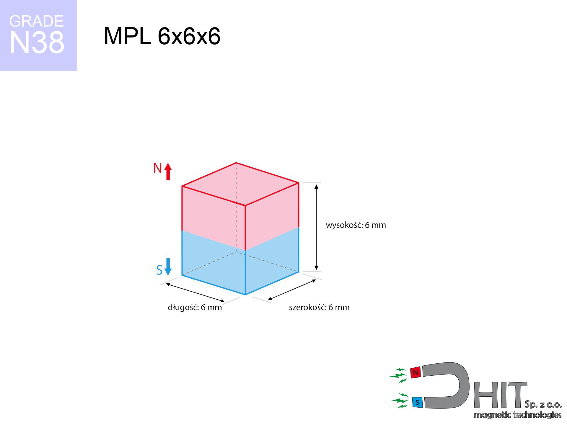
MPL 6x6x6 / N38 - lamellar magnet
lamellar magnet
Catalog no 020175
GTIN/EAN: 5906301811817
- length
- 6 mm [±0,1 mm]
- Width
- 6 mm [±0,1 mm]
- Height
- 6 mm [±0,1 mm]
- Weight
- 1.62 g
- Magnetization Direction
- ↑ axial
- Coating
- [NiCuNi] Nickel
How we measure these parameters — certificates and measurements
0.730 zł net / pcs
0.898 zł with VAT (23% VAT) / pcs
bulk discounts:
Need more?Frequently asked questions
What pull rating should I choose for a workshop block magnet?
Are block neodymium magnets available in more durable versions?
How should I choose block magnets for mounting a structure?
Engineering report for this magnet
Full PDF analysis: pull and shear force, effect of distance, temperature and plate thickness, safety distances and the demagnetization curve.
Call us now
+48 888 99 98 98
alternatively let us know using
contact form
the contact section.
Specifications and structure of a neodymium magnet can be estimated using our
power calculator.
Order by 14:00 and we’ll ship today!
Technical of the product - MPL 6x6x6 / N38 - lamellar magnet
Specification / characteristics - MPL 6x6x6 / N38 - lamellar magnet
| properties | values |
|---|---|
| Cat. no. | 020175 |
| GTIN/EAN | 5906301811817 |
| Production/Distribution | Dhit sp. z o.o. |
| Country of origin | Poland / China / Germany |
| Customs code | 85059029 |
| length | 6 mm [±0,1 mm] |
| Width | 6 mm [±0,1 mm] |
| Height | 6 mm [±0,1 mm] |
| Weight | 1.62 g |
| Magnetization Direction | ↑ axial |
| Load capacity ~ ? | 1.38 kg / 13.54 N |
| Magnetic Induction ~ ? | 539.50 mT / 5395 Gs |
| Coating | [NiCuNi] Nickel |
| Manufacturing Tolerance | ±0.1 mm |
Magnetic properties of material N38
| properties | values | units |
|---|---|---|
| Remanence Br ? | 12.2-12.6 | kGs |
| Remanence Br ? | 1220-1260 | mT |
| Coercivity bHc ? | 10.8-11.5 | kOe |
| Coercivity bHc ? | 860-915 | kA/m |
| Intrinsic coercivity iHc | ≥ 12 | kOe |
| Intrinsic coercivity iHc | ≥ 955 | kA/m |
| Energy product BHmax ? | 36-38 | BH max MGOe |
| Energy product BHmax ? | 287-303 | BH max KJ/m |
| Maximum working temperature ? | ≤ 80 | °C |
Physical properties of sintered neodymium magnets Nd2Fe14B at 20°C
| properties | values | units |
|---|---|---|
| Vickers hardness | ≥550 | Hv |
| Density | ≥7.4 | g/cm3 |
| Curie Temperature TC | 310 | °C |
| Curie Temperature TF | 590 | °F |
| Specific resistance | 150 | μΩ⋅cm |
| Bending strength | 250 | MPa |
| Compressive strength | 1000~1100 | MPa |
| Thermal expansion parallel (∥) to orientation (M) | (3-4) x 10-6 | °C-1 |
| Thermal expansion perpendicular (⊥) to orientation (M) | -(1-3) x 10-6 | °C-1 |
| Young's modulus | 1.7 x 10⁴ | kg/mm² |
Engineering analysis of the assembly - technical parameters
The following information are the outcome of a physical simulation. Values were calculated on algorithms for the material Nd2Fe14B. Operational performance may differ from theoretical values. Please consider these calculations as a reference point when designing systems.
Table 1: Static pull force (force vs gap) - characteristics
MPL 6x6x6 / N38
| Distance (mm) | Induction (Gauss) / mT | Pull Force (kg/lbs/g/N) | Risk Status |
|---|---|---|---|
| 0 mm |
5389 Gs
538.9 mT
|
1.38 kg / 3.04 pounds
1380.0 g / 13.5 N
|
weak grip |
| 1 mm |
3805 Gs
380.5 mT
|
0.69 kg / 1.52 pounds
688.0 g / 6.7 N
|
weak grip |
| 2 mm |
2530 Gs
253.0 mT
|
0.30 kg / 0.67 pounds
304.3 g / 3.0 N
|
weak grip |
| 3 mm |
1671 Gs
167.1 mT
|
0.13 kg / 0.29 pounds
132.7 g / 1.3 N
|
weak grip |
| 5 mm |
784 Gs
78.4 mT
|
0.03 kg / 0.06 pounds
29.2 g / 0.3 N
|
weak grip |
| 10 mm |
192 Gs
19.2 mT
|
0.00 kg / 0.00 pounds
1.8 g / 0.0 N
|
weak grip |
| 15 mm |
73 Gs
7.3 mT
|
0.00 kg / 0.00 pounds
0.3 g / 0.0 N
|
weak grip |
| 20 mm |
35 Gs
3.5 mT
|
0.00 kg / 0.00 pounds
0.1 g / 0.0 N
|
weak grip |
| 30 mm |
12 Gs
1.2 mT
|
0.00 kg / 0.00 pounds
0.0 g / 0.0 N
|
weak grip |
| 50 mm |
3 Gs
0.3 mT
|
0.00 kg / 0.00 pounds
0.0 g / 0.0 N
|
weak grip |
Table 2: Shear load (wall)
MPL 6x6x6 / N38
| Distance (mm) | Friction coefficient | Pull Force (kg/lbs/g/N) |
|---|---|---|
| 0 mm | Stal (~0.2) |
0.28 kg / 0.61 pounds
276.0 g / 2.7 N
|
| 1 mm | Stal (~0.2) |
0.14 kg / 0.30 pounds
138.0 g / 1.4 N
|
| 2 mm | Stal (~0.2) |
0.06 kg / 0.13 pounds
60.0 g / 0.6 N
|
| 3 mm | Stal (~0.2) |
0.03 kg / 0.06 pounds
26.0 g / 0.3 N
|
| 5 mm | Stal (~0.2) |
0.01 kg / 0.01 pounds
6.0 g / 0.1 N
|
| 10 mm | Stal (~0.2) |
0.00 kg / 0.00 pounds
0.0 g / 0.0 N
|
| 15 mm | Stal (~0.2) |
0.00 kg / 0.00 pounds
0.0 g / 0.0 N
|
| 20 mm | Stal (~0.2) |
0.00 kg / 0.00 pounds
0.0 g / 0.0 N
|
| 30 mm | Stal (~0.2) |
0.00 kg / 0.00 pounds
0.0 g / 0.0 N
|
| 50 mm | Stal (~0.2) |
0.00 kg / 0.00 pounds
0.0 g / 0.0 N
|
Table 3: Wall mounting (sliding) - behavior on slippery surfaces
MPL 6x6x6 / N38
| Surface type | Friction coefficient / % Mocy | Max load (kg/lbs/g/N) |
|---|---|---|
| Raw steel |
µ = 0.3
30% Nominalnej Siły
|
0.41 kg / 0.91 pounds
414.0 g / 4.1 N
|
| Painted steel (standard) |
µ = 0.2
20% Nominalnej Siły
|
0.28 kg / 0.61 pounds
276.0 g / 2.7 N
|
| Oily/slippery steel |
µ = 0.1
10% Nominalnej Siły
|
0.14 kg / 0.30 pounds
138.0 g / 1.4 N
|
| Magnet with anti-slip rubber |
µ = 0.5
50% Nominalnej Siły
|
0.69 kg / 1.52 pounds
690.0 g / 6.8 N
|
Table 4: Material efficiency (substrate influence) - sheet metal selection
MPL 6x6x6 / N38
| Steel thickness (mm) | % power | Real pull force (kg/lbs/g/N) |
|---|---|---|
| 0.5 mm |
|
0.14 kg / 0.30 pounds
138.0 g / 1.4 N
|
| 1 mm |
|
0.35 kg / 0.76 pounds
345.0 g / 3.4 N
|
| 2 mm |
|
0.69 kg / 1.52 pounds
690.0 g / 6.8 N
|
| 3 mm |
|
1.04 kg / 2.28 pounds
1035.0 g / 10.2 N
|
| 5 mm |
|
1.38 kg / 3.04 pounds
1380.0 g / 13.5 N
|
| 10 mm |
|
1.38 kg / 3.04 pounds
1380.0 g / 13.5 N
|
| 11 mm |
|
1.38 kg / 3.04 pounds
1380.0 g / 13.5 N
|
| 12 mm |
|
1.38 kg / 3.04 pounds
1380.0 g / 13.5 N
|
Table 5: Thermal resistance (material behavior) - power drop
MPL 6x6x6 / N38
| Ambient temp. (°C) | Power loss | Remaining pull (kg/lbs/g/N) | Status |
|---|---|---|---|
| 20 °C | 0.0% |
1.38 kg / 3.04 pounds
1380.0 g / 13.5 N
|
OK |
| 40 °C | -2.2% |
1.35 kg / 2.98 pounds
1349.6 g / 13.2 N
|
OK |
| 60 °C | -4.4% |
1.32 kg / 2.91 pounds
1319.3 g / 12.9 N
|
OK |
| 80 °C | -6.6% |
1.29 kg / 2.84 pounds
1288.9 g / 12.6 N
|
|
| 100 °C | -28.8% |
0.98 kg / 2.17 pounds
982.6 g / 9.6 N
|
Table 6: Two magnets (attraction) - field collision
MPL 6x6x6 / N38
| Gap (mm) | Attraction (kg/lbs) (N-S) | Sliding Force (kg/lbs/g/N) | Repulsion (kg/lbs) (N-N) |
|---|---|---|---|
| 0 mm |
6.44 kg / 14.21 pounds
5 949 Gs
|
0.97 kg / 2.13 pounds
967 g / 9.5 N
|
N/A |
| 1 mm |
4.66 kg / 10.28 pounds
9 167 Gs
|
0.70 kg / 1.54 pounds
699 g / 6.9 N
|
4.20 kg / 9.25 pounds
~0 Gs
|
| 2 mm |
3.21 kg / 7.08 pounds
7 610 Gs
|
0.48 kg / 1.06 pounds
482 g / 4.7 N
|
2.89 kg / 6.38 pounds
~0 Gs
|
| 3 mm |
2.15 kg / 4.74 pounds
6 228 Gs
|
0.32 kg / 0.71 pounds
323 g / 3.2 N
|
1.94 kg / 4.27 pounds
~0 Gs
|
| 5 mm |
0.94 kg / 2.06 pounds
4 107 Gs
|
0.14 kg / 0.31 pounds
140 g / 1.4 N
|
0.84 kg / 1.86 pounds
~0 Gs
|
| 10 mm |
0.14 kg / 0.30 pounds
1 568 Gs
|
0.02 kg / 0.05 pounds
20 g / 0.2 N
|
0.12 kg / 0.27 pounds
~0 Gs
|
| 20 mm |
0.01 kg / 0.02 pounds
384 Gs
|
0.00 kg / 0.00 pounds
1 g / 0.0 N
|
0.00 kg / 0.00 pounds
~0 Gs
|
| 50 mm |
0.00 kg / 0.00 pounds
39 Gs
|
0.00 kg / 0.00 pounds
0 g / 0.0 N
|
0.00 kg / 0.00 pounds
~0 Gs
|
| 60 mm |
0.00 kg / 0.00 pounds
24 Gs
|
0.00 kg / 0.00 pounds
0 g / 0.0 N
|
0.00 kg / 0.00 pounds
~0 Gs
|
| 70 mm |
0.00 kg / 0.00 pounds
16 Gs
|
0.00 kg / 0.00 pounds
0 g / 0.0 N
|
0.00 kg / 0.00 pounds
~0 Gs
|
| 80 mm |
0.00 kg / 0.00 pounds
11 Gs
|
0.00 kg / 0.00 pounds
0 g / 0.0 N
|
0.00 kg / 0.00 pounds
~0 Gs
|
| 90 mm |
0.00 kg / 0.00 pounds
8 Gs
|
0.00 kg / 0.00 pounds
0 g / 0.0 N
|
0.00 kg / 0.00 pounds
~0 Gs
|
| 100 mm |
0.00 kg / 0.00 pounds
6 Gs
|
0.00 kg / 0.00 pounds
0 g / 0.0 N
|
0.00 kg / 0.00 pounds
~0 Gs
|
Table 7: Protective zones (electronics) - precautionary measures
MPL 6x6x6 / N38
| Object / Device | Limit (Gauss) / mT | Safe distance |
|---|---|---|
| Pacemaker | 5 Gs (0.5 mT) | 4.5 cm |
| Hearing aid | 10 Gs (1.0 mT) | 3.5 cm |
| Mechanical watch | 20 Gs (2.0 mT) | 2.5 cm |
| Phone / Smartphone | 40 Gs (4.0 mT) | 2.0 cm |
| Car key | 50 Gs (5.0 mT) | 2.0 cm |
| Payment card | 400 Gs (40.0 mT) | 1.0 cm |
| HDD hard drive | 600 Gs (60.0 mT) | 1.0 cm |
Table 8: Impact energy (kinetic energy) - collision effects
MPL 6x6x6 / N38
| Start from (mm) | Speed (km/h) | Energy (J) | Predicted outcome |
|---|---|---|---|
| 10 mm |
17.13 km/h
(4.76 m/s)
|
0.02 J | |
| 30 mm |
17.15 km/h
(4.76 m/s)
|
0.02 J | |
| 50 mm |
17.15 km/h
(4.76 m/s)
|
0.02 J | |
| 100 mm |
17.16 km/h
(4.77 m/s)
|
0.02 J |
Table 9: Surface protection spec
MPL 6x6x6 / N38
| Technical parameter | Value / Description |
|---|---|
| Coating type | [NiCuNi] Nickel |
| Layer structure | Nickel - Copper - Nickel |
| Layer thickness | 10-20 µm |
| Salt spray test (SST) ? | 24 h |
| Recommended environment | Indoors only (dry) |
Table 10: Electrical data (Pc)
MPL 6x6x6 / N38
| Parameter | Value | SI Unit / Description |
|---|---|---|
| Magnetic Flux | 1 982 Mx | 19.8 µWb |
| Pc Coefficient | 0.84 | High (Stable) |
Table 11: Submerged application
MPL 6x6x6 / N38
| Environment | Effective steel pull | Effect |
|---|---|---|
| Air (land) | 1.38 kg | Standard |
| Water (riverbed) |
1.58 kg
(+0.20 kg buoyancy gain)
|
+14.5% |
1. Sliding resistance
*Note: On a vertical wall, the magnet holds just a fraction of its nominal pull.
2. Steel saturation
*Thin steel (e.g. 0.5mm PC case) drastically reduces the holding force.
3. Power loss vs temp
N38: the maximum material working temperature is 80°C. Permitted conditions also depend on the shape and magnetic circuit.
4. Demagnetization curve and operating point (B-H)
chart generated for the permeance coefficient Pc (Permeance Coefficient) = 0.84
The chart above illustrates the magnetic characteristics of the material within the second quadrant of the hysteresis loop. The solid red line represents the demagnetization curve (material potential), while the dashed blue line is the load line based on the magnet's geometry. The Pc (Permeance Coefficient), also known as the load line slope, is a dimensionless value that describes the relationship between the magnet's shape and its magnetic stability. The intersection of these two lines (the black dot) is the operating point — it determines the actual magnetic flux density generated by the magnet in this specific configuration. A higher Pc value means the magnet is more 'slender' (tall relative to its area), resulting in a higher operating point and better resistance to irreversible demagnetization caused by external fields or temperature. A value of 0.42 is relatively low (typical for flat magnets), meaning the operating point is closer to the 'knee' of the curve — caution is advised when operating at temperatures near the maximum limit to avoid strength loss.
Elemental analysis
| iron (Fe) | 64% – 68% |
| neodymium (Nd) | 29% – 32% |
| boron (B) | 1.1% – 1.2% |
| dysprosium (Dy) | 0.5% – 2.0% |
| coating (Ni-Cu-Ni) | < 0.05% |
Sustainability
| recyclability (EoL) | 100% |
| recycled raw materials | ~10% (pre-cons) |
| carbon footprint | low / zredukowany |
| waste code (EWC) | 16 02 16 |
Check out also products


![UMGZ 36x18x8 [M6] GZ / N38 - magnetic holder external thread](https://cdn3.dhit.pl/graphics/products/um-36x18x8-m8-gz-xiv.jpg "UMGZ 36x18x8 [M6] GZ / N38 - magnetic holder external thread")
Advantages as well as disadvantages of Nd2Fe14B magnets.
Pros
- They retain attractive force for around 10 years – the loss is just ~1% (according to analyses),
- They have excellent resistance to magnetic field loss when exposed to opposing magnetic fields,
- In other words, due to the glossy layer of nickel, the element becomes visually attractive,
- Magnetic induction on the working layer of the magnet is very high,
- Thanks to resistance to high temperature, they are capable of working (depending on the form) even at temperatures up to 230°C and higher...
- Possibility of precise modeling and optimizing to atypical requirements,
- Fundamental importance in electronics industry – they serve a role in computer drives, electric drive systems, medical equipment, also industrial machines.
- Thanks to their power density, small magnets offer high operating force, in miniature format,
Disadvantages
- At strong impacts they can crack, therefore we recommend placing them in steel cases. A metal housing provides additional protection against damage, as well as increases the magnet's durability.
- Do not exceed this material temperature limit: 80°C. Overheating may permanently weaken the magnet.
- They oxidize in a humid environment - during use outdoors we recommend using waterproof magnets e.g. in rubber, plastic
- Limited possibility of making threads in the magnet and complex shapes - recommended is a housing - mounting mechanism.
- Potential hazard related to microscopic parts of magnets are risky, in case of ingestion, which becomes key in the aspect of protecting the youngest. It is also worth noting that small components of these devices are able to disrupt the diagnostic process medical after entering the body.
- High unit price – neodymium magnets cost more than other types of magnets (e.g. ferrite), which can limit application in large quantities
Holding force characteristics
Maximum lifting force for a neodymium magnet – what contributes to it?
- using a base made of high-permeability steel, acting as a ideal flux conductor
- whose transverse dimension is min. 10 mm
- with an ground contact surface
- without the slightest clearance between the magnet and steel
- under vertical force direction (90-degree angle)
- at ambient temperature room level
Impact of factors on magnetic holding capacity in practice
- Distance – the presence of foreign body (paint, tape, gap) interrupts the magnetic circuit, which reduces capacity rapidly (even by 50% at 0.5 mm).
- Pull-off angle – remember that the magnet holds strongest perpendicularly. Under shear forces, the holding force drops drastically, often to levels of 20-30% of the maximum value.
- Base massiveness – insufficiently thick steel does not close the flux, causing part of the flux to be escaped to the other side.
- Steel grade – the best choice is high-permeability steel. Stainless steels may generate lower lifting capacity.
- Surface condition – ground elements guarantee perfect abutment, which increases field saturation. Rough surfaces reduce efficiency.
- Temperature – temperature increase causes a temporary drop of force. Check the maximum operating temperature for a given model.
Lifting capacity was measured using a polished steel plate of suitable thickness (min. 20 mm), under perpendicular detachment force, however under attempts to slide the magnet the holding force is lower. Additionally, even a slight gap between the magnet and the plate reduces the lifting capacity.
Warnings
Combustion hazard
Powder generated during grinding of magnets is flammable. Do not drill into magnets without proper cooling and knowledge.
Safe operation
Use magnets with awareness. Their huge power can shock even professionals. Stay alert and respect their power.
Shattering risk
NdFeB magnets are sintered ceramics, which means they are fragile like glass. Clashing of two magnets will cause them shattering into shards.
Phone sensors
Remember: rare earth magnets generate a field that confuses sensitive sensors. Keep a safe distance from your phone, device, and GPS.
Danger to pacemakers
Patients with a heart stimulator should keep an safe separation from magnets. The magnetic field can stop the operation of the life-saving device.
This is not a toy
Only for adults. Small elements can be swallowed, causing intestinal necrosis. Keep out of reach of children and animals.
Safe distance
Avoid bringing magnets near a purse, laptop, or TV. The magnetic field can permanently damage these devices and erase data from cards.
Crushing force
Mind your fingers. Two large magnets will join instantly with a force of massive weight, crushing anything in their path. Exercise extreme caution!
Nickel allergy
It is widely known that the nickel plating (the usual finish) is a strong allergen. If your skin reacts to metals, refrain from direct skin contact or select encased magnets.
Heat warning
Standard neodymium magnets (N-type) lose magnetization when the temperature goes above 80°C. This process is irreversible.
Tabela kosztu i czasu dostawy
Płatność przed wysyłką:

GLS kurier
Przesyłka będzie u Ciebie za 2-3 dni
14.99 ZŁ

InPost Paczkomaty 24/7
Przesyłka będzie u Ciebie za 1-2 dni
12.30 ZŁ
Płatność przy odbiorze (pobranie):
GLS kurier
Przesyłka będzie u Ciebie za 1-2 dni
23.00 ZŁ