

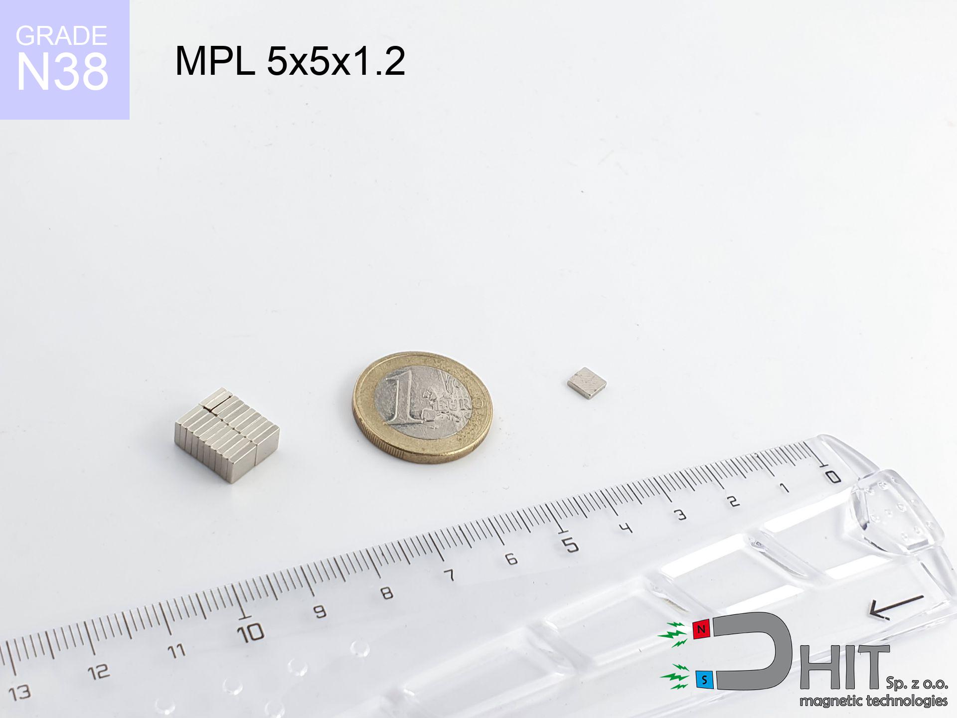
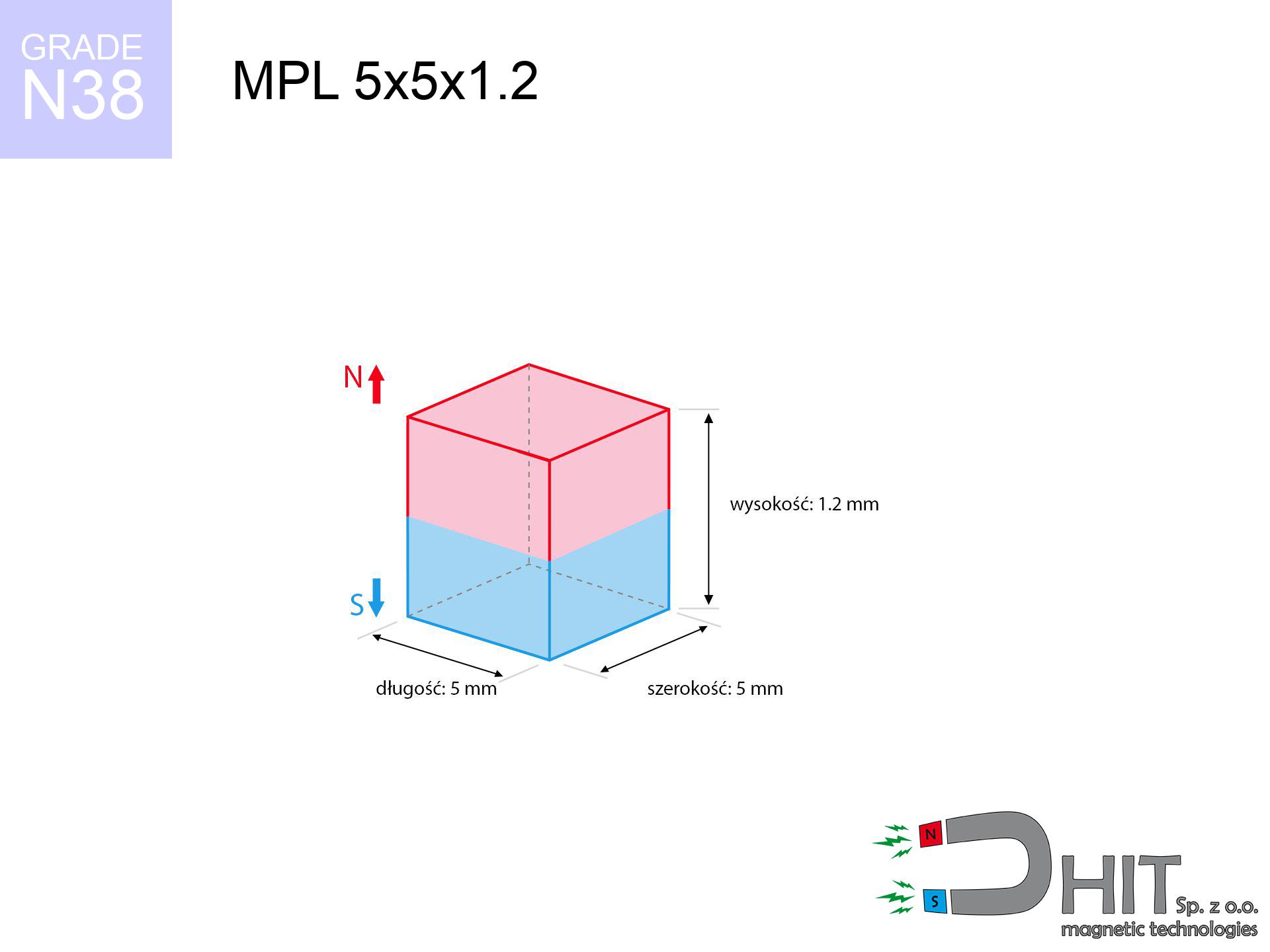
MPL 5x5x1.2 / N38 - lamellar magnet
lamellar magnet
Catalog no 020171
GTIN/EAN: 5906301811770
- length
- 5 mm [±0,1 mm]
- Width
- 5 mm [±0,1 mm]
- Height
- 1.2 mm [±0,1 mm]
- Weight
- 0.22 g
- Magnetization Direction
- ↑ axial
- Coating
- [NiCuNi] Nickel
How we measure these parameters — certificates and measurements
0.1500 zł net / pcs
0.1845 zł with VAT (23% VAT) / pcs
bulk discounts:
Need more?Frequently asked questions
What pull rating should I choose for a workshop block magnet?
Are block neodymium magnets available in more durable versions?
How should I choose block magnets for mounting a structure?
Engineering report for this magnet
Full PDF analysis: pull and shear force, effect of distance, temperature and plate thickness, safety distances and the demagnetization curve.
Call us now
+48 888 99 98 98
alternatively let us know using
contact form
the contact section.
Specifications and structure of a neodymium magnet can be estimated using our
power calculator.
Order by 14:00 and we’ll ship today!
Technical of the product - MPL 5x5x1.2 / N38 - lamellar magnet
Specification / characteristics - MPL 5x5x1.2 / N38 - lamellar magnet
| properties | values |
|---|---|
| Cat. no. | 020171 |
| GTIN/EAN | 5906301811770 |
| Production/Distribution | Dhit sp. z o.o. |
| Country of origin | Poland / China / Germany |
| Customs code | 85059029 |
| length | 5 mm [±0,1 mm] |
| Width | 5 mm [±0,1 mm] |
| Height | 1.2 mm [±0,1 mm] |
| Weight | 0.22 g |
| Magnetization Direction | ↑ axial |
| Load capacity ~ ? | 0.44 kg / 4.28 N |
| Magnetic Induction ~ ? | 245.17 mT / 2452 Gs |
| Coating | [NiCuNi] Nickel |
| Manufacturing Tolerance | ±0.1 mm |
Magnetic properties of material N38
| properties | values | units |
|---|---|---|
| Remanence Br ? | 12.2-12.6 | kGs |
| Remanence Br ? | 1220-1260 | mT |
| Coercivity bHc ? | 10.8-11.5 | kOe |
| Coercivity bHc ? | 860-915 | kA/m |
| Intrinsic coercivity iHc | ≥ 12 | kOe |
| Intrinsic coercivity iHc | ≥ 955 | kA/m |
| Energy product BHmax ? | 36-38 | BH max MGOe |
| Energy product BHmax ? | 287-303 | BH max KJ/m |
| Maximum working temperature ? | ≤ 80 | °C |
Physical properties of sintered neodymium magnets Nd2Fe14B at 20°C
| properties | values | units |
|---|---|---|
| Vickers hardness | ≥550 | Hv |
| Density | ≥7.4 | g/cm3 |
| Curie Temperature TC | 310 | °C |
| Curie Temperature TF | 590 | °F |
| Specific resistance | 150 | μΩ⋅cm |
| Bending strength | 250 | MPa |
| Compressive strength | 1000~1100 | MPa |
| Thermal expansion parallel (∥) to orientation (M) | (3-4) x 10-6 | °C-1 |
| Thermal expansion perpendicular (⊥) to orientation (M) | -(1-3) x 10-6 | °C-1 |
| Young's modulus | 1.7 x 10⁴ | kg/mm² |
Engineering modeling of the product - technical parameters
Presented information constitute the direct effect of a mathematical simulation. Values rely on models for the class Nd2Fe14B. Actual conditions might slightly differ from theoretical values. Use these data as a reference point for designers.
Table 1: Static force (pull vs distance) - interaction chart
MPL 5x5x1.2 / N38
| Distance (mm) | Induction (Gauss) / mT | Pull Force (kg/lbs/g/N) | Risk Status |
|---|---|---|---|
| 0 mm |
2450 Gs
245.0 mT
|
0.44 kg / 0.97 LBS
440.0 g / 4.3 N
|
safe |
| 1 mm |
1739 Gs
173.9 mT
|
0.22 kg / 0.49 LBS
221.8 g / 2.2 N
|
safe |
| 2 mm |
1054 Gs
105.4 mT
|
0.08 kg / 0.18 LBS
81.4 g / 0.8 N
|
safe |
| 3 mm |
622 Gs
62.2 mT
|
0.03 kg / 0.06 LBS
28.4 g / 0.3 N
|
safe |
| 5 mm |
241 Gs
24.1 mT
|
0.00 kg / 0.01 LBS
4.3 g / 0.0 N
|
safe |
| 10 mm |
45 Gs
4.5 mT
|
0.00 kg / 0.00 LBS
0.1 g / 0.0 N
|
safe |
| 15 mm |
15 Gs
1.5 mT
|
0.00 kg / 0.00 LBS
0.0 g / 0.0 N
|
safe |
| 20 mm |
7 Gs
0.7 mT
|
0.00 kg / 0.00 LBS
0.0 g / 0.0 N
|
safe |
| 30 mm |
2 Gs
0.2 mT
|
0.00 kg / 0.00 LBS
0.0 g / 0.0 N
|
safe |
| 50 mm |
0 Gs
0.0 mT
|
0.00 kg / 0.00 LBS
0.0 g / 0.0 N
|
safe |
Table 2: Vertical load (wall)
MPL 5x5x1.2 / N38
| Distance (mm) | Friction coefficient | Pull Force (kg/lbs/g/N) |
|---|---|---|
| 0 mm | Stal (~0.2) |
0.09 kg / 0.19 LBS
88.0 g / 0.9 N
|
| 1 mm | Stal (~0.2) |
0.04 kg / 0.10 LBS
44.0 g / 0.4 N
|
| 2 mm | Stal (~0.2) |
0.02 kg / 0.04 LBS
16.0 g / 0.2 N
|
| 3 mm | Stal (~0.2) |
0.01 kg / 0.01 LBS
6.0 g / 0.1 N
|
| 5 mm | Stal (~0.2) |
0.00 kg / 0.00 LBS
0.0 g / 0.0 N
|
| 10 mm | Stal (~0.2) |
0.00 kg / 0.00 LBS
0.0 g / 0.0 N
|
| 15 mm | Stal (~0.2) |
0.00 kg / 0.00 LBS
0.0 g / 0.0 N
|
| 20 mm | Stal (~0.2) |
0.00 kg / 0.00 LBS
0.0 g / 0.0 N
|
| 30 mm | Stal (~0.2) |
0.00 kg / 0.00 LBS
0.0 g / 0.0 N
|
| 50 mm | Stal (~0.2) |
0.00 kg / 0.00 LBS
0.0 g / 0.0 N
|
Table 3: Vertical assembly (sliding) - vertical pull
MPL 5x5x1.2 / N38
| Surface type | Friction coefficient / % Mocy | Max load (kg/lbs/g/N) |
|---|---|---|
| Raw steel |
µ = 0.3
30% Nominalnej Siły
|
0.13 kg / 0.29 LBS
132.0 g / 1.3 N
|
| Painted steel (standard) |
µ = 0.2
20% Nominalnej Siły
|
0.09 kg / 0.19 LBS
88.0 g / 0.9 N
|
| Oily/slippery steel |
µ = 0.1
10% Nominalnej Siły
|
0.04 kg / 0.10 LBS
44.0 g / 0.4 N
|
| Magnet with anti-slip rubber |
µ = 0.5
50% Nominalnej Siły
|
0.22 kg / 0.49 LBS
220.0 g / 2.2 N
|
Table 4: Steel thickness (substrate influence) - power losses
MPL 5x5x1.2 / N38
| Steel thickness (mm) | % power | Real pull force (kg/lbs/g/N) |
|---|---|---|
| 0.5 mm |
|
0.04 kg / 0.10 LBS
44.0 g / 0.4 N
|
| 1 mm |
|
0.11 kg / 0.24 LBS
110.0 g / 1.1 N
|
| 2 mm |
|
0.22 kg / 0.49 LBS
220.0 g / 2.2 N
|
| 3 mm |
|
0.33 kg / 0.73 LBS
330.0 g / 3.2 N
|
| 5 mm |
|
0.44 kg / 0.97 LBS
440.0 g / 4.3 N
|
| 10 mm |
|
0.44 kg / 0.97 LBS
440.0 g / 4.3 N
|
| 11 mm |
|
0.44 kg / 0.97 LBS
440.0 g / 4.3 N
|
| 12 mm |
|
0.44 kg / 0.97 LBS
440.0 g / 4.3 N
|
Table 5: Working in heat (material behavior) - resistance threshold
MPL 5x5x1.2 / N38
| Ambient temp. (°C) | Power loss | Remaining pull (kg/lbs/g/N) | Status |
|---|---|---|---|
| 20 °C | 0.0% |
0.44 kg / 0.97 LBS
440.0 g / 4.3 N
|
OK |
| 40 °C | -2.2% |
0.43 kg / 0.95 LBS
430.3 g / 4.2 N
|
OK |
| 60 °C | -4.4% |
0.42 kg / 0.93 LBS
420.6 g / 4.1 N
|
|
| 80 °C | -6.6% |
0.41 kg / 0.91 LBS
411.0 g / 4.0 N
|
|
| 100 °C | -28.8% |
0.31 kg / 0.69 LBS
313.3 g / 3.1 N
|
Table 6: Magnet-Magnet interaction (attraction) - field collision
MPL 5x5x1.2 / N38
| Gap (mm) | Attraction (kg/lbs) (N-S) | Shear Strength (kg/lbs/g/N) | Repulsion (kg/lbs) (N-N) |
|---|---|---|---|
| 0 mm |
0.92 kg / 2.04 LBS
4 027 Gs
|
0.14 kg / 0.31 LBS
139 g / 1.4 N
|
N/A |
| 1 mm |
0.70 kg / 1.54 LBS
4 260 Gs
|
0.10 kg / 0.23 LBS
105 g / 1.0 N
|
0.63 kg / 1.39 LBS
~0 Gs
|
| 2 mm |
0.47 kg / 1.03 LBS
3 478 Gs
|
0.07 kg / 0.15 LBS
70 g / 0.7 N
|
0.42 kg / 0.93 LBS
~0 Gs
|
| 3 mm |
0.29 kg / 0.63 LBS
2 734 Gs
|
0.04 kg / 0.10 LBS
43 g / 0.4 N
|
0.26 kg / 0.57 LBS
~0 Gs
|
| 5 mm |
0.10 kg / 0.22 LBS
1 617 Gs
|
0.02 kg / 0.03 LBS
15 g / 0.1 N
|
0.09 kg / 0.20 LBS
~0 Gs
|
| 10 mm |
0.01 kg / 0.02 LBS
482 Gs
|
0.00 kg / 0.00 LBS
1 g / 0.0 N
|
0.00 kg / 0.00 LBS
~0 Gs
|
| 20 mm |
0.00 kg / 0.00 LBS
90 Gs
|
0.00 kg / 0.00 LBS
0 g / 0.0 N
|
0.00 kg / 0.00 LBS
~0 Gs
|
| 50 mm |
0.00 kg / 0.00 LBS
7 Gs
|
0.00 kg / 0.00 LBS
0 g / 0.0 N
|
0.00 kg / 0.00 LBS
~0 Gs
|
| 60 mm |
0.00 kg / 0.00 LBS
4 Gs
|
0.00 kg / 0.00 LBS
0 g / 0.0 N
|
0.00 kg / 0.00 LBS
~0 Gs
|
| 70 mm |
0.00 kg / 0.00 LBS
3 Gs
|
0.00 kg / 0.00 LBS
0 g / 0.0 N
|
0.00 kg / 0.00 LBS
~0 Gs
|
| 80 mm |
0.00 kg / 0.00 LBS
2 Gs
|
0.00 kg / 0.00 LBS
0 g / 0.0 N
|
0.00 kg / 0.00 LBS
~0 Gs
|
| 90 mm |
0.00 kg / 0.00 LBS
1 Gs
|
0.00 kg / 0.00 LBS
0 g / 0.0 N
|
0.00 kg / 0.00 LBS
~0 Gs
|
| 100 mm |
0.00 kg / 0.00 LBS
1 Gs
|
0.00 kg / 0.00 LBS
0 g / 0.0 N
|
0.00 kg / 0.00 LBS
~0 Gs
|
Table 7: Hazards (electronics) - warnings
MPL 5x5x1.2 / N38
| Object / Device | Limit (Gauss) / mT | Safe distance |
|---|---|---|
| Pacemaker | 5 Gs (0.5 mT) | 2.5 cm |
| Hearing aid | 10 Gs (1.0 mT) | 2.0 cm |
| Timepiece | 20 Gs (2.0 mT) | 1.5 cm |
| Mobile device | 40 Gs (4.0 mT) | 1.5 cm |
| Car key | 50 Gs (5.0 mT) | 1.0 cm |
| Payment card | 400 Gs (40.0 mT) | 0.5 cm |
| HDD hard drive | 600 Gs (60.0 mT) | 0.5 cm |
Table 8: Impact energy (kinetic energy) - warning
MPL 5x5x1.2 / N38
| Start from (mm) | Speed (km/h) | Energy (J) | Predicted outcome |
|---|---|---|---|
| 10 mm |
25.39 km/h
(7.05 m/s)
|
0.01 J | |
| 30 mm |
25.39 km/h
(7.05 m/s)
|
0.01 J | |
| 50 mm |
25.36 km/h
(7.05 m/s)
|
0.01 J | |
| 100 mm |
25.40 km/h
(7.06 m/s)
|
0.01 J |
Table 9: Coating parameters (durability)
MPL 5x5x1.2 / N38
| Technical parameter | Value / Description |
|---|---|
| Coating type | [NiCuNi] Nickel |
| Layer structure | Nickel - Copper - Nickel |
| Layer thickness | 10-20 µm |
| Salt spray test (SST) ? | 24 h |
| Recommended environment | Indoors only (dry) |
Table 10: Electrical data (Pc)
MPL 5x5x1.2 / N38
| Parameter | Value | SI Unit / Description |
|---|---|---|
| Magnetic Flux | 695 Mx | 7.0 µWb |
| Pc Coefficient | 0.30 | Low (Flat) |
Table 11: Underwater work (magnet fishing)
MPL 5x5x1.2 / N38
| Environment | Effective steel pull | Effect |
|---|---|---|
| Air (land) | 0.44 kg | Standard |
| Water (riverbed) |
0.50 kg
(+0.06 kg buoyancy gain)
|
+14.5% |
1. Sliding resistance
*Caution: On a vertical wall, the magnet retains merely a fraction of its max power.
2. Steel thickness impact
*Thin steel (e.g. 0.5mm PC case) significantly reduces the holding force.
3. Thermal stability
N38: the maximum material working temperature is 80°C. Permitted conditions also depend on the shape and magnetic circuit.
4. Demagnetization curve and operating point (B-H)
chart generated for the permeance coefficient Pc (Permeance Coefficient) = 0.30
The chart above illustrates the magnetic characteristics of the material within the second quadrant of the hysteresis loop. The solid red line represents the demagnetization curve (material potential), while the dashed blue line is the load line based on the magnet's geometry. The Pc (Permeance Coefficient), also known as the load line slope, is a dimensionless value that describes the relationship between the magnet's shape and its magnetic stability. The intersection of these two lines (the black dot) is the operating point — it determines the actual magnetic flux density generated by the magnet in this specific configuration. A higher Pc value means the magnet is more 'slender' (tall relative to its area), resulting in a higher operating point and better resistance to irreversible demagnetization caused by external fields or temperature. A value of 0.42 is relatively low (typical for flat magnets), meaning the operating point is closer to the 'knee' of the curve — caution is advised when operating at temperatures near the maximum limit to avoid strength loss.
Chemical composition
| iron (Fe) | 64% – 68% |
| neodymium (Nd) | 29% – 32% |
| boron (B) | 1.1% – 1.2% |
| dysprosium (Dy) | 0.5% – 2.0% |
| coating (Ni-Cu-Ni) | < 0.05% |
Environmental data
| recyclability (EoL) | 100% |
| recycled raw materials | ~10% (pre-cons) |
| carbon footprint | low / zredukowany |
| waste code (EWC) | 16 02 16 |
View also deals
![SM 28x150 [2xM8] / N52 - magnetic separator](https://cdn3.dhit.pl/graphics/products/sm-28x150-2xm8-bon.jpg "SM 28x150 [2xM8] / N52 - magnetic separator")


Advantages and disadvantages of Nd2Fe14B magnets.
Strengths
- They retain full power for around ten years – the loss is just ~1% (according to analyses),
- They possess excellent resistance to magnetism drop when exposed to external fields,
- The use of an aesthetic finish of noble metals (nickel, gold, silver) causes the element to have aesthetics,
- Neodymium magnets create maximum magnetic induction on a contact point, which ensures high operational effectiveness,
- Due to their durability and thermal resistance, neodymium magnets can operate (depending on the shape) even at high temperatures reaching 230°C or more...
- Due to the option of accurate forming and customization to unique solutions, neodymium magnets can be produced in a variety of forms and dimensions, which increases their versatility,
- Significant place in innovative solutions – they serve a role in data components, motor assemblies, medical devices, and industrial machines.
- Relatively small size with high pulling force – neodymium magnets offer impressive pulling force in small dimensions, which enables their usage in small systems
Limitations
- Susceptibility to cracking is one of their disadvantages. Upon strong impact they can fracture. We recommend keeping them in a special holder, which not only secures them against impacts but also raises their durability
- Do not exceed this material temperature limit: 80°C. Overheating may permanently weaken the magnet.
- Magnets exposed to a humid environment can corrode. Therefore while using outdoors, we advise using waterproof magnets made of rubber, plastic or other material resistant to moisture
- Limited possibility of producing nuts in the magnet and complex forms - preferred is casing - magnet mounting.
- Potential hazard to health – tiny shards of magnets can be dangerous, if swallowed, which becomes key in the aspect of protecting the youngest. Additionally, tiny parts of these devices can complicate diagnosis medical after entering the body.
- Higher cost of purchase is one of the disadvantages compared to ceramic magnets, especially in budget applications
Pull force analysis
Detachment force of the magnet in optimal conditions – what contributes to it?
- using a base made of low-carbon steel, functioning as a magnetic yoke
- possessing a thickness of min. 10 mm to ensure full flux closure
- characterized by lack of roughness
- without the slightest clearance between the magnet and steel
- for force applied at a right angle (pull-off, not shear)
- in neutral thermal conditions
Impact of factors on magnetic holding capacity in practice
- Gap (betwixt the magnet and the plate), because even a tiny distance (e.g. 0.5 mm) results in a reduction in lifting capacity by up to 50% (this also applies to paint, corrosion or dirt).
- Load vector – highest force is reached only during perpendicular pulling. The shear force of the magnet along the plate is typically many times smaller (approx. 1/5 of the lifting capacity).
- Wall thickness – the thinner the sheet, the weaker the hold. Magnetic flux penetrates through instead of generating force.
- Metal type – different alloys reacts the same. High carbon content worsen the attraction effect.
- Surface finish – full contact is possible only on smooth steel. Rough texture reduce the real contact area, reducing force.
- Operating temperature – neodymium magnets have a negative temperature coefficient. At higher temperatures they lose power, and at low temperatures gain strength (up to a certain limit).
Lifting capacity was assessed using a smooth steel plate of optimal thickness (min. 20 mm), under vertically applied force, however under shearing force the load capacity is reduced by as much as 75%. Moreover, even a slight gap between the magnet’s surface and the plate decreases the holding force.
Safe handling of NdFeB magnets
Fire warning
Powder created during grinding of magnets is combustible. Do not drill into magnets unless you are an expert.
Electronic hazard
Avoid bringing magnets near a purse, laptop, or TV. The magnetism can destroy these devices and erase data from cards.
Finger safety
Mind your fingers. Two large magnets will snap together immediately with a force of massive weight, destroying everything in their path. Be careful!
Warning for allergy sufferers
Certain individuals experience a sensitization to nickel, which is the common plating for NdFeB magnets. Prolonged contact might lead to skin redness. We strongly advise use protective gloves.
Material brittleness
Despite the nickel coating, neodymium is delicate and not impact-resistant. Avoid impacts, as the magnet may shatter into sharp, dangerous pieces.
Product not for children
Neodymium magnets are not toys. Eating multiple magnets may result in them attracting across intestines, which poses a severe health hazard and requires urgent medical intervention.
Health Danger
Warning for patients: Strong magnetic fields disrupt electronics. Keep minimum 30 cm distance or ask another person to handle the magnets.
Maximum temperature
Standard neodymium magnets (N-type) lose power when the temperature surpasses 80°C. The loss of strength is permanent.
Respect the power
Before use, read the rules. Uncontrolled attraction can break the magnet or hurt your hand. Think ahead.
Keep away from electronics
Navigation devices and mobile phones are highly sensitive to magnetism. Close proximity with a powerful NdFeB magnet can decalibrate the internal compass in your phone.
Tabela kosztu i czasu dostawy
Płatność przed wysyłką:

GLS kurier
Przesyłka będzie u Ciebie za 2-3 dni
14.99 ZŁ

InPost Paczkomaty 24/7
Przesyłka będzie u Ciebie za 1-2 dni
12.30 ZŁ
Płatność przy odbiorze (pobranie):
GLS kurier
Przesyłka będzie u Ciebie za 1-2 dni
23.00 ZŁ