


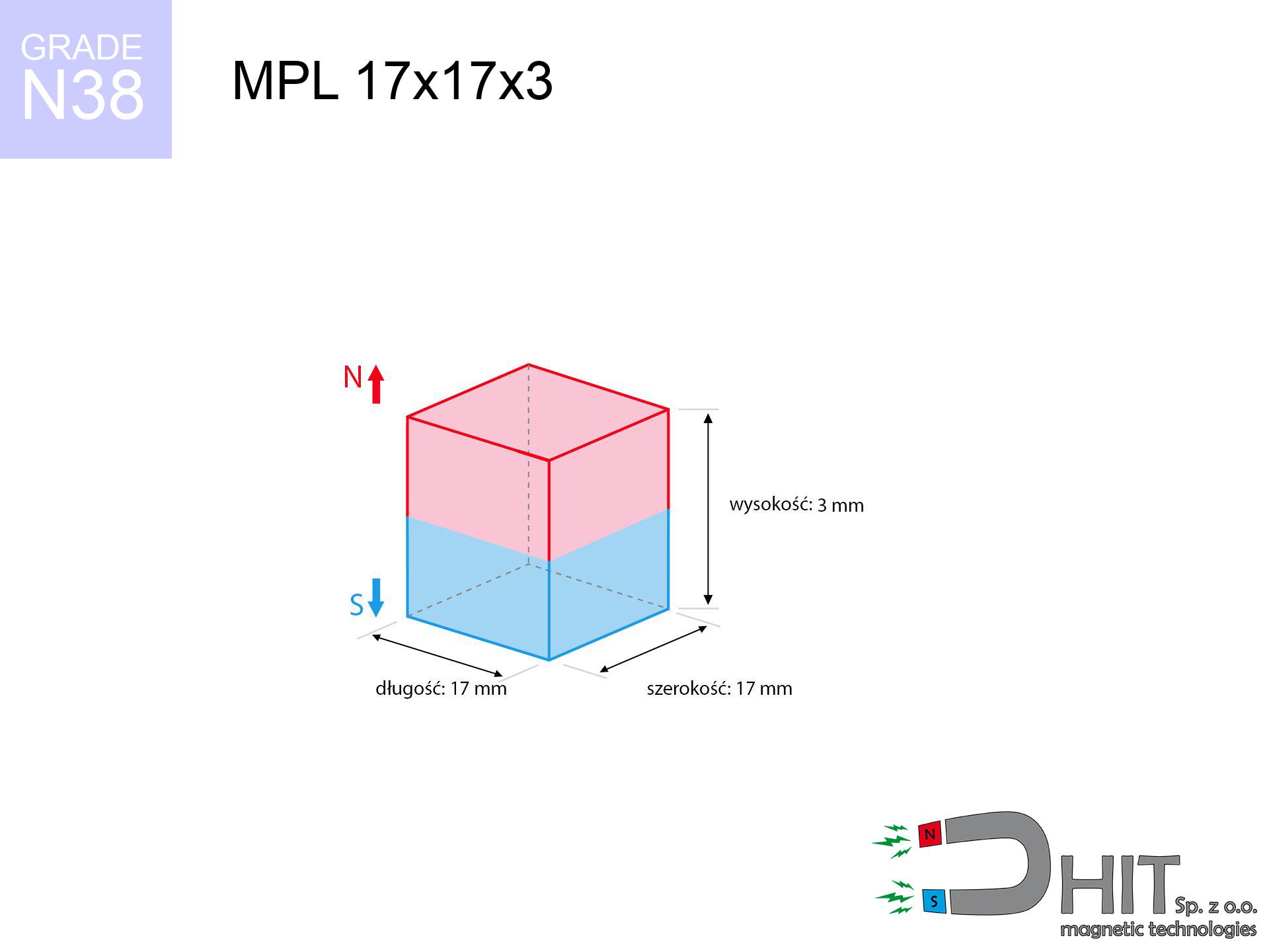
MPL 17x17x3 / N38 - lamellar magnet
lamellar magnet
Catalog no 020124
GTIN/EAN: 5906301811305
- length
- 17 mm [±0,1 mm]
- Width
- 17 mm [±0,1 mm]
- Height
- 3 mm [±0,1 mm]
- Weight
- 6.5 g
- Magnetization Direction
- ↑ axial
- Coating
- [NiCuNi] Nickel
How we measure these parameters — certificates and measurements
3.83 zł net / pcs
4.71 zł with VAT (23% VAT) / pcs
bulk discounts:
Need more?Frequently asked questions
What pull rating should I choose for a workshop block magnet?
Are block neodymium magnets available in more durable versions?
How should I choose block magnets for mounting a structure?
Engineering report for this magnet
Full PDF analysis: pull and shear force, effect of distance, temperature and plate thickness, safety distances and the demagnetization curve.
Call us now
+48 888 99 98 98
alternatively let us know using
contact form
the contact section.
Specifications and structure of a neodymium magnet can be estimated using our
power calculator.
Order by 14:00 and we’ll ship today!
Technical data of the product - MPL 17x17x3 / N38 - lamellar magnet
Specification / characteristics - MPL 17x17x3 / N38 - lamellar magnet
| properties | values |
|---|---|
| Cat. no. | 020124 |
| GTIN/EAN | 5906301811305 |
| Production/Distribution | Dhit sp. z o.o. |
| Country of origin | Poland / China / Germany |
| Customs code | 85059029 |
| length | 17 mm [±0,1 mm] |
| Width | 17 mm [±0,1 mm] |
| Height | 3 mm [±0,1 mm] |
| Weight | 6.5 g |
| Magnetization Direction | ↑ axial |
| Load capacity ~ ? | 3.22 kg / 31.54 N |
| Magnetic Induction ~ ? | 187.48 mT / 1875 Gs |
| Coating | [NiCuNi] Nickel |
| Manufacturing Tolerance | ±0.1 mm |
Magnetic properties of material N38
| properties | values | units |
|---|---|---|
| Remanence Br ? | 12.2-12.6 | kGs |
| Remanence Br ? | 1220-1260 | mT |
| Coercivity bHc ? | 10.8-11.5 | kOe |
| Coercivity bHc ? | 860-915 | kA/m |
| Intrinsic coercivity iHc | ≥ 12 | kOe |
| Intrinsic coercivity iHc | ≥ 955 | kA/m |
| Energy product BHmax ? | 36-38 | BH max MGOe |
| Energy product BHmax ? | 287-303 | BH max KJ/m |
| Maximum working temperature ? | ≤ 80 | °C |
Physical properties of sintered neodymium magnets Nd2Fe14B at 20°C
| properties | values | units |
|---|---|---|
| Vickers hardness | ≥550 | Hv |
| Density | ≥7.4 | g/cm3 |
| Curie Temperature TC | 310 | °C |
| Curie Temperature TF | 590 | °F |
| Specific resistance | 150 | μΩ⋅cm |
| Bending strength | 250 | MPa |
| Compressive strength | 1000~1100 | MPa |
| Thermal expansion parallel (∥) to orientation (M) | (3-4) x 10-6 | °C-1 |
| Thermal expansion perpendicular (⊥) to orientation (M) | -(1-3) x 10-6 | °C-1 |
| Young's modulus | 1.7 x 10⁴ | kg/mm² |
Technical simulation of the magnet - report
Presented values are the result of a mathematical simulation. Results were calculated on models for the material Nd2Fe14B. Actual conditions may differ. Treat these data as a reference point during assembly planning.
Table 1: Static pull force (pull vs gap) - power drop
MPL 17x17x3 / N38
| Distance (mm) | Induction (Gauss) / mT | Pull Force (kg/lbs/g/N) | Risk Status |
|---|---|---|---|
| 0 mm |
1874 Gs
187.4 mT
|
3.22 kg / 7.10 pounds
3220.0 g / 31.6 N
|
warning |
| 1 mm |
1761 Gs
176.1 mT
|
2.84 kg / 6.27 pounds
2842.9 g / 27.9 N
|
warning |
| 2 mm |
1610 Gs
161.0 mT
|
2.38 kg / 5.24 pounds
2376.8 g / 23.3 N
|
warning |
| 3 mm |
1440 Gs
144.0 mT
|
1.90 kg / 4.19 pounds
1901.0 g / 18.6 N
|
weak grip |
| 5 mm |
1099 Gs
109.9 mT
|
1.11 kg / 2.44 pounds
1107.5 g / 10.9 N
|
weak grip |
| 10 mm |
508 Gs
50.8 mT
|
0.24 kg / 0.52 pounds
236.4 g / 2.3 N
|
weak grip |
| 15 mm |
245 Gs
24.5 mT
|
0.06 kg / 0.12 pounds
55.2 g / 0.5 N
|
weak grip |
| 20 mm |
131 Gs
13.1 mT
|
0.02 kg / 0.03 pounds
15.7 g / 0.2 N
|
weak grip |
| 30 mm |
48 Gs
4.8 mT
|
0.00 kg / 0.00 pounds
2.1 g / 0.0 N
|
weak grip |
| 50 mm |
12 Gs
1.2 mT
|
0.00 kg / 0.00 pounds
0.1 g / 0.0 N
|
weak grip |
Table 2: Shear load (wall)
MPL 17x17x3 / N38
| Distance (mm) | Friction coefficient | Pull Force (kg/lbs/g/N) |
|---|---|---|
| 0 mm | Stal (~0.2) |
0.64 kg / 1.42 pounds
644.0 g / 6.3 N
|
| 1 mm | Stal (~0.2) |
0.57 kg / 1.25 pounds
568.0 g / 5.6 N
|
| 2 mm | Stal (~0.2) |
0.48 kg / 1.05 pounds
476.0 g / 4.7 N
|
| 3 mm | Stal (~0.2) |
0.38 kg / 0.84 pounds
380.0 g / 3.7 N
|
| 5 mm | Stal (~0.2) |
0.22 kg / 0.49 pounds
222.0 g / 2.2 N
|
| 10 mm | Stal (~0.2) |
0.05 kg / 0.11 pounds
48.0 g / 0.5 N
|
| 15 mm | Stal (~0.2) |
0.01 kg / 0.03 pounds
12.0 g / 0.1 N
|
| 20 mm | Stal (~0.2) |
0.00 kg / 0.01 pounds
4.0 g / 0.0 N
|
| 30 mm | Stal (~0.2) |
0.00 kg / 0.00 pounds
0.0 g / 0.0 N
|
| 50 mm | Stal (~0.2) |
0.00 kg / 0.00 pounds
0.0 g / 0.0 N
|
Table 3: Wall mounting (sliding) - behavior on slippery surfaces
MPL 17x17x3 / N38
| Surface type | Friction coefficient / % Mocy | Max load (kg/lbs/g/N) |
|---|---|---|
| Raw steel |
µ = 0.3
30% Nominalnej Siły
|
0.97 kg / 2.13 pounds
966.0 g / 9.5 N
|
| Painted steel (standard) |
µ = 0.2
20% Nominalnej Siły
|
0.64 kg / 1.42 pounds
644.0 g / 6.3 N
|
| Oily/slippery steel |
µ = 0.1
10% Nominalnej Siły
|
0.32 kg / 0.71 pounds
322.0 g / 3.2 N
|
| Magnet with anti-slip rubber |
µ = 0.5
50% Nominalnej Siły
|
1.61 kg / 3.55 pounds
1610.0 g / 15.8 N
|
Table 4: Steel thickness (substrate influence) - power losses
MPL 17x17x3 / N38
| Steel thickness (mm) | % power | Real pull force (kg/lbs/g/N) |
|---|---|---|
| 0.5 mm |
|
0.32 kg / 0.71 pounds
322.0 g / 3.2 N
|
| 1 mm |
|
0.81 kg / 1.77 pounds
805.0 g / 7.9 N
|
| 2 mm |
|
1.61 kg / 3.55 pounds
1610.0 g / 15.8 N
|
| 3 mm |
|
2.42 kg / 5.32 pounds
2415.0 g / 23.7 N
|
| 5 mm |
|
3.22 kg / 7.10 pounds
3220.0 g / 31.6 N
|
| 10 mm |
|
3.22 kg / 7.10 pounds
3220.0 g / 31.6 N
|
| 11 mm |
|
3.22 kg / 7.10 pounds
3220.0 g / 31.6 N
|
| 12 mm |
|
3.22 kg / 7.10 pounds
3220.0 g / 31.6 N
|
Table 5: Thermal resistance (stability) - resistance threshold
MPL 17x17x3 / N38
| Ambient temp. (°C) | Power loss | Remaining pull (kg/lbs/g/N) | Status |
|---|---|---|---|
| 20 °C | 0.0% |
3.22 kg / 7.10 pounds
3220.0 g / 31.6 N
|
OK |
| 40 °C | -2.2% |
3.15 kg / 6.94 pounds
3149.2 g / 30.9 N
|
OK |
| 60 °C | -4.4% |
3.08 kg / 6.79 pounds
3078.3 g / 30.2 N
|
|
| 80 °C | -6.6% |
3.01 kg / 6.63 pounds
3007.5 g / 29.5 N
|
|
| 100 °C | -28.8% |
2.29 kg / 5.05 pounds
2292.6 g / 22.5 N
|
Table 6: Magnet-Magnet interaction (attraction) - field range
MPL 17x17x3 / N38
| Gap (mm) | Attraction (kg/lbs) (N-S) | Lateral Force (kg/lbs/g/N) | Repulsion (kg/lbs) (N-N) |
|---|---|---|---|
| 0 mm |
6.26 kg / 13.80 pounds
3 313 Gs
|
0.94 kg / 2.07 pounds
939 g / 9.2 N
|
N/A |
| 1 mm |
5.93 kg / 13.07 pounds
3 648 Gs
|
0.89 kg / 1.96 pounds
889 g / 8.7 N
|
5.33 kg / 11.76 pounds
~0 Gs
|
| 2 mm |
5.53 kg / 12.19 pounds
3 523 Gs
|
0.83 kg / 1.83 pounds
829 g / 8.1 N
|
4.97 kg / 10.97 pounds
~0 Gs
|
| 3 mm |
5.08 kg / 11.21 pounds
3 379 Gs
|
0.76 kg / 1.68 pounds
763 g / 7.5 N
|
4.58 kg / 10.09 pounds
~0 Gs
|
| 5 mm |
4.15 kg / 9.16 pounds
3 053 Gs
|
0.62 kg / 1.37 pounds
623 g / 6.1 N
|
3.74 kg / 8.24 pounds
~0 Gs
|
| 10 mm |
2.15 kg / 4.75 pounds
2 199 Gs
|
0.32 kg / 0.71 pounds
323 g / 3.2 N
|
1.94 kg / 4.27 pounds
~0 Gs
|
| 20 mm |
0.46 kg / 1.01 pounds
1 016 Gs
|
0.07 kg / 0.15 pounds
69 g / 0.7 N
|
0.41 kg / 0.91 pounds
~0 Gs
|
| 50 mm |
0.01 kg / 0.02 pounds
153 Gs
|
0.00 kg / 0.00 pounds
2 g / 0.0 N
|
0.01 kg / 0.02 pounds
~0 Gs
|
| 60 mm |
0.00 kg / 0.01 pounds
96 Gs
|
0.00 kg / 0.00 pounds
1 g / 0.0 N
|
0.00 kg / 0.00 pounds
~0 Gs
|
| 70 mm |
0.00 kg / 0.00 pounds
64 Gs
|
0.00 kg / 0.00 pounds
0 g / 0.0 N
|
0.00 kg / 0.00 pounds
~0 Gs
|
| 80 mm |
0.00 kg / 0.00 pounds
44 Gs
|
0.00 kg / 0.00 pounds
0 g / 0.0 N
|
0.00 kg / 0.00 pounds
~0 Gs
|
| 90 mm |
0.00 kg / 0.00 pounds
32 Gs
|
0.00 kg / 0.00 pounds
0 g / 0.0 N
|
0.00 kg / 0.00 pounds
~0 Gs
|
| 100 mm |
0.00 kg / 0.00 pounds
24 Gs
|
0.00 kg / 0.00 pounds
0 g / 0.0 N
|
0.00 kg / 0.00 pounds
~0 Gs
|
Table 7: Safety (HSE) (electronics) - warnings
MPL 17x17x3 / N38
| Object / Device | Limit (Gauss) / mT | Safe distance |
|---|---|---|
| Pacemaker | 5 Gs (0.5 mT) | 7.0 cm |
| Hearing aid | 10 Gs (1.0 mT) | 5.5 cm |
| Timepiece | 20 Gs (2.0 mT) | 4.5 cm |
| Phone / Smartphone | 40 Gs (4.0 mT) | 3.5 cm |
| Car key | 50 Gs (5.0 mT) | 3.0 cm |
| Payment card | 400 Gs (40.0 mT) | 1.5 cm |
| HDD hard drive | 600 Gs (60.0 mT) | 1.0 cm |
Table 8: Dynamics (cracking risk) - warning
MPL 17x17x3 / N38
| Start from (mm) | Speed (km/h) | Energy (J) | Predicted outcome |
|---|---|---|---|
| 10 mm |
23.10 km/h
(6.42 m/s)
|
0.13 J | |
| 30 mm |
23.79 km/h
(6.61 m/s)
|
0.14 J | |
| 50 mm |
23.78 km/h
(6.61 m/s)
|
0.14 J | |
| 100 mm |
23.80 km/h
(6.61 m/s)
|
0.14 J |
Table 9: Coating parameters (durability)
MPL 17x17x3 / N38
| Technical parameter | Value / Description |
|---|---|
| Coating type | [NiCuNi] Nickel |
| Layer structure | Nickel - Copper - Nickel |
| Layer thickness | 10-20 µm |
| Salt spray test (SST) ? | 24 h |
| Recommended environment | Indoors only (dry) |
Table 10: Electrical data (Pc)
MPL 17x17x3 / N38
| Parameter | Value | SI Unit / Description |
|---|---|---|
| Magnetic Flux | 6 509 Mx | 65.1 µWb |
| Pc Coefficient | 0.23 | Low (Flat) |
Table 11: Underwater work (magnet fishing)
MPL 17x17x3 / N38
| Environment | Effective steel pull | Effect |
|---|---|---|
| Air (land) | 3.22 kg | Standard |
| Water (riverbed) |
3.69 kg
(+0.47 kg buoyancy gain)
|
+14.5% |
1. Sliding resistance
*Caution: On a vertical surface, the magnet holds just approx. 20-30% of its max power.
2. Efficiency vs thickness
*Thin steel (e.g. 0.5mm PC case) significantly weakens the holding force.
3. Temperature resistance
N38: the maximum material working temperature is 80°C. Permitted conditions also depend on the shape and magnetic circuit.
4. Demagnetization curve and operating point (B-H)
chart generated for the permeance coefficient Pc (Permeance Coefficient) = 0.23
This simulation demonstrates the magnetic stability of the selected magnet under specific geometric conditions. The solid red line represents the demagnetization curve (material potential), while the dashed blue line is the load line based on the magnet's geometry. The Pc (Permeance Coefficient), also known as the load line slope, is a dimensionless value that describes the relationship between the magnet's shape and its magnetic stability. The intersection of these two lines (the black dot) is the operating point — it determines the actual magnetic flux density generated by the magnet in this specific configuration. A higher Pc value means the magnet is more 'slender' (tall relative to its area), resulting in a higher operating point and better resistance to irreversible demagnetization caused by external fields or temperature. A value of 0.42 is relatively low (typical for flat magnets), meaning the operating point is closer to the 'knee' of the curve — caution is advised when operating at temperatures near the maximum limit to avoid strength loss.
Material specification
| iron (Fe) | 64% – 68% |
| neodymium (Nd) | 29% – 32% |
| boron (B) | 1.1% – 1.2% |
| dysprosium (Dy) | 0.5% – 2.0% |
| coating (Ni-Cu-Ni) | < 0.05% |
Environmental data
| recyclability (EoL) | 100% |
| recycled raw materials | ~10% (pre-cons) |
| carbon footprint | low / zredukowany |
| waste code (EWC) | 16 02 16 |
Other products
![SM 25x200 [2xM8] / N52 - magnetic separator](https://cdn3.dhit.pl/graphics/products/sm-25x200-2xm8-jas.jpg "SM 25x200 [2xM8] / N52 - magnetic separator")
![SM 28x325 [2xM8] / N52 - magnetic separator](https://cdn3.dhit.pl/graphics/products/sm-28x325-2xm8-puf.jpg "SM 28x325 [2xM8] / N52 - magnetic separator")
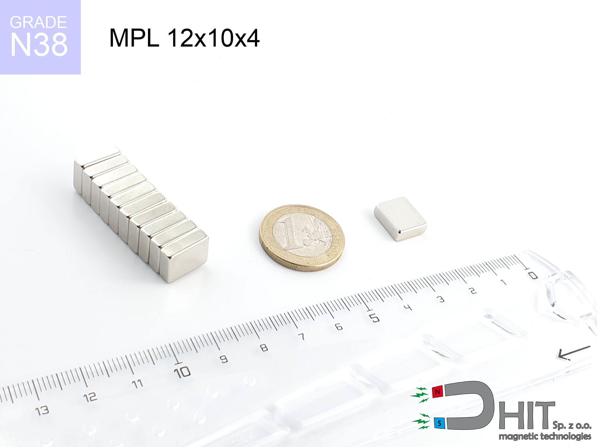
Strengths as well as weaknesses of neodymium magnets.
Benefits
- Their magnetic field is maintained, and after around 10 years it drops only by ~1% (theoretically),
- They are resistant to demagnetization induced by external magnetic fields,
- A magnet with a metallic gold surface has better aesthetics,
- Neodymium magnets deliver maximum magnetic induction on a small surface, which increases force concentration,
- Due to their durability and thermal resistance, neodymium magnets can operate (depending on the form) even at high temperatures reaching 230°C or more...
- Thanks to modularity in forming and the ability to modify to specific needs,
- Key role in future technologies – they are commonly used in mass storage devices, electromotive mechanisms, medical equipment, and complex engineering applications.
- Compactness – despite small sizes they provide effective action, making them ideal for precision applications
Cons
- Brittleness is one of their disadvantages. Upon strong impact they can break. We recommend keeping them in a strong case, which not only protects them against impacts but also increases their durability
- Do not exceed this material temperature limit: 80°C. Overheating may permanently weaken the magnet.
- When exposed to humidity, magnets usually rust. To use them in conditions outside, it is recommended to use protective magnets, such as those in rubber or plastics, which prevent oxidation and corrosion.
- Limited possibility of creating nuts in the magnet and complex forms - recommended is cover - mounting mechanism.
- Health risk resulting from small fragments of magnets can be dangerous, when accidentally swallowed, which becomes key in the context of child health protection. Additionally, small components of these products can disrupt the diagnostic process medical after entering the body.
- High unit price – neodymium magnets are more expensive than other types of magnets (e.g. ferrite), which can limit application in large quantities
Pull force analysis
Maximum holding power of the magnet – what it depends on?
- with the contact of a yoke made of low-carbon steel, ensuring maximum field concentration
- possessing a thickness of minimum 10 mm to ensure full flux closure
- with a plane free of scratches
- without any air gap between the magnet and steel
- for force applied at a right angle (pull-off, not shear)
- at temperature approx. 20 degrees Celsius
Practical lifting capacity: influencing factors
- Air gap (betwixt the magnet and the plate), since even a tiny clearance (e.g. 0.5 mm) leads to a drastic drop in lifting capacity by up to 50% (this also applies to paint, rust or dirt).
- Direction of force – maximum parameter is reached only during perpendicular pulling. The resistance to sliding of the magnet along the plate is usually many times smaller (approx. 1/5 of the lifting capacity).
- Element thickness – for full efficiency, the steel must be adequately massive. Paper-thin metal restricts the attraction force (the magnet "punches through" it).
- Steel grade – ideal substrate is pure iron steel. Stainless steels may attract less.
- Surface structure – the more even the plate, the larger the contact zone and higher the lifting capacity. Unevenness acts like micro-gaps.
- Thermal factor – hot environment reduces magnetic field. Exceeding the limit temperature can permanently damage the magnet.
Holding force was measured on a smooth steel plate of 20 mm thickness, when a perpendicular force was applied, however under attempts to slide the magnet the holding force is lower. Additionally, even a minimal clearance between the magnet’s surface and the plate lowers the holding force.
Safety rules for work with NdFeB magnets
Conscious usage
Handle magnets consciously. Their immense force can shock even professionals. Stay alert and respect their power.
Maximum temperature
Standard neodymium magnets (grade N) lose power when the temperature goes above 80°C. The loss of strength is permanent.
This is not a toy
Only for adults. Small elements pose a choking risk, causing severe trauma. Keep out of reach of kids and pets.
Magnet fragility
Neodymium magnets are sintered ceramics, which means they are very brittle. Impact of two magnets will cause them cracking into shards.
Metal Allergy
It is widely known that the nickel plating (the usual finish) is a strong allergen. If you have an allergy, refrain from touching magnets with bare hands or opt for coated magnets.
Crushing force
Mind your fingers. Two large magnets will snap together immediately with a force of massive weight, destroying everything in their path. Be careful!
Health Danger
Patients with a pacemaker have to maintain an large gap from magnets. The magnetism can disrupt the functioning of the life-saving device.
Safe distance
Data protection: Strong magnets can ruin payment cards and sensitive devices (pacemakers, medical aids, mechanical watches).
GPS and phone interference
A strong magnetic field interferes with the operation of magnetometers in smartphones and navigation systems. Maintain magnets near a device to prevent breaking the sensors.
Do not drill into magnets
Powder produced during machining of magnets is flammable. Avoid drilling into magnets without proper cooling and knowledge.
Tabela kosztu i czasu dostawy
Płatność przed wysyłką:

GLS kurier
Przesyłka będzie u Ciebie za 2-3 dni
14.99 ZŁ

InPost Paczkomaty 24/7
Przesyłka będzie u Ciebie za 1-2 dni
12.30 ZŁ
Płatność przy odbiorze (pobranie):
GLS kurier
Przesyłka będzie u Ciebie za 1-2 dni
23.00 ZŁ