


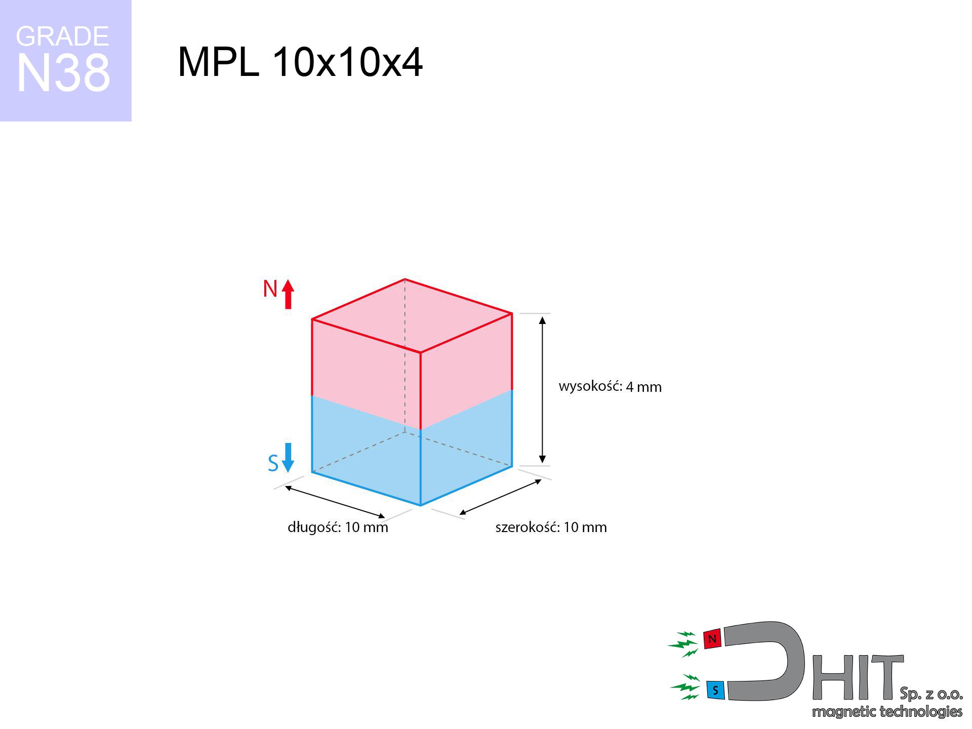
MPL 10x10x4 / N38 - lamellar magnet
lamellar magnet
Catalog no 020112
GTIN/EAN: 5906301811183
- length
- 10 mm [±0,1 mm]
- Width
- 10 mm [±0,1 mm]
- Height
- 4 mm [±0,1 mm]
- Weight
- 3 g
- Magnetization Direction
- ↑ axial
- Coating
- [NiCuNi] Nickel
How we measure these parameters — certificates and measurements
1.250 zł net / pcs
1.538 zł with VAT (23% VAT) / pcs
bulk discounts:
Need more?Frequently asked questions
What pull rating should I choose for a workshop block magnet?
Are block neodymium magnets available in more durable versions?
How should I choose block magnets for mounting a structure?
Engineering report for this magnet
Full PDF analysis: pull and shear force, effect of distance, temperature and plate thickness, safety distances and the demagnetization curve.
Call us now
+48 888 99 98 98
alternatively let us know using
contact form
the contact section.
Specifications and structure of a neodymium magnet can be estimated using our
power calculator.
Order by 14:00 and we’ll ship today!
Technical specification - MPL 10x10x4 / N38 - lamellar magnet
Specification / characteristics - MPL 10x10x4 / N38 - lamellar magnet
| properties | values |
|---|---|
| Cat. no. | 020112 |
| GTIN/EAN | 5906301811183 |
| Production/Distribution | Dhit sp. z o.o. |
| Country of origin | Poland / China / Germany |
| Customs code | 85059029 |
| length | 10 mm [±0,1 mm] |
| Width | 10 mm [±0,1 mm] |
| Height | 4 mm [±0,1 mm] |
| Weight | 3 g |
| Magnetization Direction | ↑ axial |
| Load capacity ~ ? | 3.10 kg / 30.39 N |
| Magnetic Induction ~ ? | 360.85 mT / 3608 Gs |
| Coating | [NiCuNi] Nickel |
| Manufacturing Tolerance | ±0.1 mm |
Magnetic properties of material N38
| properties | values | units |
|---|---|---|
| Remanence Br ? | 12.2-12.6 | kGs |
| Remanence Br ? | 1220-1260 | mT |
| Coercivity bHc ? | 10.8-11.5 | kOe |
| Coercivity bHc ? | 860-915 | kA/m |
| Intrinsic coercivity iHc | ≥ 12 | kOe |
| Intrinsic coercivity iHc | ≥ 955 | kA/m |
| Energy product BHmax ? | 36-38 | BH max MGOe |
| Energy product BHmax ? | 287-303 | BH max KJ/m |
| Maximum working temperature ? | ≤ 80 | °C |
Physical properties of sintered neodymium magnets Nd2Fe14B at 20°C
| properties | values | units |
|---|---|---|
| Vickers hardness | ≥550 | Hv |
| Density | ≥7.4 | g/cm3 |
| Curie Temperature TC | 310 | °C |
| Curie Temperature TF | 590 | °F |
| Specific resistance | 150 | μΩ⋅cm |
| Bending strength | 250 | MPa |
| Compressive strength | 1000~1100 | MPa |
| Thermal expansion parallel (∥) to orientation (M) | (3-4) x 10-6 | °C-1 |
| Thermal expansion perpendicular (⊥) to orientation (M) | -(1-3) x 10-6 | °C-1 |
| Young's modulus | 1.7 x 10⁴ | kg/mm² |
Technical analysis of the product - technical parameters
These information constitute the direct effect of a physical simulation. Values were calculated on models for the material Nd2Fe14B. Actual conditions might slightly deviate from the simulation results. Please consider these data as a supplementary guide during assembly planning.
Table 1: Static force (pull vs gap) - characteristics
MPL 10x10x4 / N38
| Distance (mm) | Induction (Gauss) / mT | Pull Force (kg/lbs/g/N) | Risk Status |
|---|---|---|---|
| 0 mm |
3606 Gs
360.6 mT
|
3.10 kg / 6.83 lbs
3100.0 g / 30.4 N
|
warning |
| 1 mm |
3035 Gs
303.5 mT
|
2.20 kg / 4.84 lbs
2195.5 g / 21.5 N
|
warning |
| 2 mm |
2436 Gs
243.6 mT
|
1.41 kg / 3.12 lbs
1413.8 g / 13.9 N
|
safe |
| 3 mm |
1900 Gs
190.0 mT
|
0.86 kg / 1.90 lbs
860.8 g / 8.4 N
|
safe |
| 5 mm |
1127 Gs
112.7 mT
|
0.30 kg / 0.67 lbs
302.7 g / 3.0 N
|
safe |
| 10 mm |
347 Gs
34.7 mT
|
0.03 kg / 0.06 lbs
28.8 g / 0.3 N
|
safe |
| 15 mm |
140 Gs
14.0 mT
|
0.00 kg / 0.01 lbs
4.6 g / 0.0 N
|
safe |
| 20 mm |
68 Gs
6.8 mT
|
0.00 kg / 0.00 lbs
1.1 g / 0.0 N
|
safe |
| 30 mm |
23 Gs
2.3 mT
|
0.00 kg / 0.00 lbs
0.1 g / 0.0 N
|
safe |
| 50 mm |
6 Gs
0.6 mT
|
0.00 kg / 0.00 lbs
0.0 g / 0.0 N
|
safe |
Table 2: Sliding capacity (wall)
MPL 10x10x4 / N38
| Distance (mm) | Friction coefficient | Pull Force (kg/lbs/g/N) |
|---|---|---|
| 0 mm | Stal (~0.2) |
0.62 kg / 1.37 lbs
620.0 g / 6.1 N
|
| 1 mm | Stal (~0.2) |
0.44 kg / 0.97 lbs
440.0 g / 4.3 N
|
| 2 mm | Stal (~0.2) |
0.28 kg / 0.62 lbs
282.0 g / 2.8 N
|
| 3 mm | Stal (~0.2) |
0.17 kg / 0.38 lbs
172.0 g / 1.7 N
|
| 5 mm | Stal (~0.2) |
0.06 kg / 0.13 lbs
60.0 g / 0.6 N
|
| 10 mm | Stal (~0.2) |
0.01 kg / 0.01 lbs
6.0 g / 0.1 N
|
| 15 mm | Stal (~0.2) |
0.00 kg / 0.00 lbs
0.0 g / 0.0 N
|
| 20 mm | Stal (~0.2) |
0.00 kg / 0.00 lbs
0.0 g / 0.0 N
|
| 30 mm | Stal (~0.2) |
0.00 kg / 0.00 lbs
0.0 g / 0.0 N
|
| 50 mm | Stal (~0.2) |
0.00 kg / 0.00 lbs
0.0 g / 0.0 N
|
Table 3: Vertical assembly (sliding) - behavior on slippery surfaces
MPL 10x10x4 / N38
| Surface type | Friction coefficient / % Mocy | Max load (kg/lbs/g/N) |
|---|---|---|
| Raw steel |
µ = 0.3
30% Nominalnej Siły
|
0.93 kg / 2.05 lbs
930.0 g / 9.1 N
|
| Painted steel (standard) |
µ = 0.2
20% Nominalnej Siły
|
0.62 kg / 1.37 lbs
620.0 g / 6.1 N
|
| Oily/slippery steel |
µ = 0.1
10% Nominalnej Siły
|
0.31 kg / 0.68 lbs
310.0 g / 3.0 N
|
| Magnet with anti-slip rubber |
µ = 0.5
50% Nominalnej Siły
|
1.55 kg / 3.42 lbs
1550.0 g / 15.2 N
|
Table 4: Steel thickness (substrate influence) - power losses
MPL 10x10x4 / N38
| Steel thickness (mm) | % power | Real pull force (kg/lbs/g/N) |
|---|---|---|
| 0.5 mm |
|
0.31 kg / 0.68 lbs
310.0 g / 3.0 N
|
| 1 mm |
|
0.78 kg / 1.71 lbs
775.0 g / 7.6 N
|
| 2 mm |
|
1.55 kg / 3.42 lbs
1550.0 g / 15.2 N
|
| 3 mm |
|
2.33 kg / 5.13 lbs
2325.0 g / 22.8 N
|
| 5 mm |
|
3.10 kg / 6.83 lbs
3100.0 g / 30.4 N
|
| 10 mm |
|
3.10 kg / 6.83 lbs
3100.0 g / 30.4 N
|
| 11 mm |
|
3.10 kg / 6.83 lbs
3100.0 g / 30.4 N
|
| 12 mm |
|
3.10 kg / 6.83 lbs
3100.0 g / 30.4 N
|
Table 5: Working in heat (stability) - thermal limit
MPL 10x10x4 / N38
| Ambient temp. (°C) | Power loss | Remaining pull (kg/lbs/g/N) | Status |
|---|---|---|---|
| 20 °C | 0.0% |
3.10 kg / 6.83 lbs
3100.0 g / 30.4 N
|
OK |
| 40 °C | -2.2% |
3.03 kg / 6.68 lbs
3031.8 g / 29.7 N
|
OK |
| 60 °C | -4.4% |
2.96 kg / 6.53 lbs
2963.6 g / 29.1 N
|
|
| 80 °C | -6.6% |
2.90 kg / 6.38 lbs
2895.4 g / 28.4 N
|
|
| 100 °C | -28.8% |
2.21 kg / 4.87 lbs
2207.2 g / 21.7 N
|
Table 6: Magnet-Magnet interaction (attraction) - field range
MPL 10x10x4 / N38
| Gap (mm) | Attraction (kg/lbs) (N-S) | Sliding Force (kg/lbs/g/N) | Repulsion (kg/lbs) (N-N) |
|---|---|---|---|
| 0 mm |
8.02 kg / 17.68 lbs
5 067 Gs
|
1.20 kg / 2.65 lbs
1203 g / 11.8 N
|
N/A |
| 1 mm |
6.85 kg / 15.11 lbs
6 667 Gs
|
1.03 kg / 2.27 lbs
1028 g / 10.1 N
|
6.17 kg / 13.59 lbs
~0 Gs
|
| 2 mm |
5.68 kg / 12.52 lbs
6 070 Gs
|
0.85 kg / 1.88 lbs
852 g / 8.4 N
|
5.11 kg / 11.27 lbs
~0 Gs
|
| 3 mm |
4.60 kg / 10.14 lbs
5 463 Gs
|
0.69 kg / 1.52 lbs
690 g / 6.8 N
|
4.14 kg / 9.13 lbs
~0 Gs
|
| 5 mm |
2.87 kg / 6.32 lbs
4 313 Gs
|
0.43 kg / 0.95 lbs
430 g / 4.2 N
|
2.58 kg / 5.69 lbs
~0 Gs
|
| 10 mm |
0.78 kg / 1.73 lbs
2 254 Gs
|
0.12 kg / 0.26 lbs
117 g / 1.2 N
|
0.70 kg / 1.55 lbs
~0 Gs
|
| 20 mm |
0.07 kg / 0.16 lbs
695 Gs
|
0.01 kg / 0.02 lbs
11 g / 0.1 N
|
0.07 kg / 0.15 lbs
~0 Gs
|
| 50 mm |
0.00 kg / 0.00 lbs
76 Gs
|
0.00 kg / 0.00 lbs
0 g / 0.0 N
|
0.00 kg / 0.00 lbs
~0 Gs
|
| 60 mm |
0.00 kg / 0.00 lbs
46 Gs
|
0.00 kg / 0.00 lbs
0 g / 0.0 N
|
0.00 kg / 0.00 lbs
~0 Gs
|
| 70 mm |
0.00 kg / 0.00 lbs
30 Gs
|
0.00 kg / 0.00 lbs
0 g / 0.0 N
|
0.00 kg / 0.00 lbs
~0 Gs
|
| 80 mm |
0.00 kg / 0.00 lbs
21 Gs
|
0.00 kg / 0.00 lbs
0 g / 0.0 N
|
0.00 kg / 0.00 lbs
~0 Gs
|
| 90 mm |
0.00 kg / 0.00 lbs
15 Gs
|
0.00 kg / 0.00 lbs
0 g / 0.0 N
|
0.00 kg / 0.00 lbs
~0 Gs
|
| 100 mm |
0.00 kg / 0.00 lbs
11 Gs
|
0.00 kg / 0.00 lbs
0 g / 0.0 N
|
0.00 kg / 0.00 lbs
~0 Gs
|
Table 7: Hazards (electronics) - warnings
MPL 10x10x4 / N38
| Object / Device | Limit (Gauss) / mT | Safe distance |
|---|---|---|
| Pacemaker | 5 Gs (0.5 mT) | 5.5 cm |
| Hearing aid | 10 Gs (1.0 mT) | 4.5 cm |
| Mechanical watch | 20 Gs (2.0 mT) | 3.5 cm |
| Mobile device | 40 Gs (4.0 mT) | 2.5 cm |
| Remote | 50 Gs (5.0 mT) | 2.5 cm |
| Payment card | 400 Gs (40.0 mT) | 1.0 cm |
| HDD hard drive | 600 Gs (60.0 mT) | 1.0 cm |
Table 8: Dynamics (cracking risk) - warning
MPL 10x10x4 / N38
| Start from (mm) | Speed (km/h) | Energy (J) | Predicted outcome |
|---|---|---|---|
| 10 mm |
24.69 km/h
(6.86 m/s)
|
0.07 J | |
| 30 mm |
24.82 km/h
(6.90 m/s)
|
0.07 J | |
| 50 mm |
24.82 km/h
(6.89 m/s)
|
0.07 J | |
| 100 mm |
24.83 km/h
(6.90 m/s)
|
0.07 J |
Table 9: Coating parameters (durability)
MPL 10x10x4 / N38
| Technical parameter | Value / Description |
|---|---|
| Coating type | [NiCuNi] Nickel |
| Layer structure | Nickel - Copper - Nickel |
| Layer thickness | 10-20 µm |
| Salt spray test (SST) ? | 24 h |
| Recommended environment | Indoors only (dry) |
Table 10: Electrical data (Pc)
MPL 10x10x4 / N38
| Parameter | Value | SI Unit / Description |
|---|---|---|
| Magnetic Flux | 3 760 Mx | 37.6 µWb |
| Pc Coefficient | 0.46 | Low (Flat) |
Table 11: Underwater work (magnet fishing)
MPL 10x10x4 / N38
| Environment | Effective steel pull | Effect |
|---|---|---|
| Air (land) | 3.10 kg | Standard |
| Water (riverbed) |
3.55 kg
(+0.45 kg buoyancy gain)
|
+14.5% |
1. Vertical hold
*Note: On a vertical wall, the magnet holds just a fraction of its perpendicular strength.
2. Steel thickness impact
*Thin steel (e.g. 0.5mm PC case) drastically weakens the holding force.
3. Power loss vs temp
N38: the maximum material working temperature is 80°C. Permitted conditions also depend on the shape and magnetic circuit.
4. Demagnetization curve and operating point (B-H)
chart generated for the permeance coefficient Pc (Permeance Coefficient) = 0.46
This simulation demonstrates the magnetic stability of the selected magnet under specific geometric conditions. The solid red line represents the demagnetization curve (material potential), while the dashed blue line is the load line based on the magnet's geometry. The Pc (Permeance Coefficient), also known as the load line slope, is a dimensionless value that describes the relationship between the magnet's shape and its magnetic stability. The intersection of these two lines (the black dot) is the operating point — it determines the actual magnetic flux density generated by the magnet in this specific configuration. A higher Pc value means the magnet is more 'slender' (tall relative to its area), resulting in a higher operating point and better resistance to irreversible demagnetization caused by external fields or temperature. A value of 0.42 is relatively low (typical for flat magnets), meaning the operating point is closer to the 'knee' of the curve — caution is advised when operating at temperatures near the maximum limit to avoid strength loss.
Elemental analysis
| iron (Fe) | 64% – 68% |
| neodymium (Nd) | 29% – 32% |
| boron (B) | 1.1% – 1.2% |
| dysprosium (Dy) | 0.5% – 2.0% |
| coating (Ni-Cu-Ni) | < 0.05% |
Sustainability
| recyclability (EoL) | 100% |
| recycled raw materials | ~10% (pre-cons) |
| carbon footprint | low / zredukowany |
| waste code (EWC) | 16 02 16 |
See more proposals
![UMP 67x28 [M8+M10] GW F120 Lina / N38 - search holder](https://cdn3.dhit.pl/graphics/products/ump-67x28-m8+m10-gw-f-120+-lina-xiw.jpg "UMP 67x28 [M8+M10] GW F120 Lina / N38 - search holder")
![SM 25x100 [2xM8] / N42 - magnetic separator](https://cdn3.dhit.pl/graphics/products/sm-25x100-2xm8-feg.jpg "SM 25x100 [2xM8] / N42 - magnetic separator")
![UMP 135x40 [M10+M12] GW F 600 kg / N38 - search holder](https://cdn3.dhit.pl/graphics/products/ump135x40-m10+m12-gw-f-600-kg-luz.jpg "UMP 135x40 [M10+M12] GW F 600 kg / N38 - search holder")

Pros as well as cons of neodymium magnets.
Pros
- They retain magnetic properties for almost 10 years – the loss is just ~1% (according to analyses),
- They have excellent resistance to weakening of magnetic properties due to external magnetic sources,
- By covering with a decorative coating of gold, the element gains an professional look,
- They feature high magnetic induction at the operating surface, making them more effective,
- Neodymium magnets are characterized by extremely high magnetic induction on the magnet surface and can function (depending on the form) even at a temperature of 230°C or more...
- Considering the potential of flexible molding and customization to unique solutions, NdFeB magnets can be produced in a wide range of shapes and sizes, which makes them more universal,
- Key role in modern industrial fields – they serve a role in hard drives, electromotive mechanisms, medical equipment, also industrial machines.
- Relatively small size with high pulling force – neodymium magnets offer impressive pulling force in compact dimensions, which enables their usage in miniature devices
Limitations
- To avoid cracks upon strong impacts, we suggest using special steel housings. Such a solution secures the magnet and simultaneously improves its durability.
- Do not exceed this material temperature limit: 80°C. Overheating may permanently weaken the magnet.
- Magnets exposed to a humid environment can corrode. Therefore when using outdoors, we recommend using waterproof magnets made of rubber, plastic or other material resistant to moisture
- We recommend cover - magnetic mechanism, due to difficulties in producing nuts inside the magnet and complex forms.
- Potential hazard related to microscopic parts of magnets can be dangerous, when accidentally swallowed, which gains importance in the aspect of protecting the youngest. Furthermore, small elements of these products are able to be problematic in diagnostics medical in case of swallowing.
- Due to expensive raw materials, their price exceeds standard values,
Holding force characteristics
Maximum lifting capacity of the magnet – what it depends on?
- with the application of a yoke made of low-carbon steel, ensuring full magnetic saturation
- with a thickness minimum 10 mm
- with a plane perfectly flat
- without the slightest insulating layer between the magnet and steel
- under vertical application of breakaway force (90-degree angle)
- at standard ambient temperature
Magnet lifting force in use – key factors
- Space between surfaces – even a fraction of a millimeter of distance (caused e.g. by varnish or dirt) significantly weakens the magnet efficiency, often by half at just 0.5 mm.
- Force direction – declared lifting capacity refers to detachment vertically. When slipping, the magnet holds significantly lower power (often approx. 20-30% of maximum force).
- Wall thickness – thin material does not allow full use of the magnet. Magnetic flux passes through the material instead of converting into lifting capacity.
- Metal type – different alloys attracts identically. High carbon content worsen the attraction effect.
- Base smoothness – the more even the plate, the better the adhesion and higher the lifting capacity. Roughness acts like micro-gaps.
- Temperature – heating the magnet causes a temporary drop of induction. It is worth remembering the maximum operating temperature for a given model.
Lifting capacity was assessed by applying a smooth steel plate of suitable thickness (min. 20 mm), under perpendicular detachment force, however under attempts to slide the magnet the holding force is lower. Moreover, even a small distance between the magnet’s surface and the plate decreases the holding force.
Warnings
Handling guide
Be careful. Neodymium magnets attract from a distance and snap with huge force, often quicker than you can move away.
Warning for allergy sufferers
Medical facts indicate that the nickel plating (the usual finish) is a potent allergen. If your skin reacts to metals, avoid touching magnets with bare hands or select coated magnets.
Electronic devices
Intense magnetic fields can destroy records on payment cards, hard drives, and other magnetic media. Maintain a gap of min. 10 cm.
Heat sensitivity
Avoid heat. Neodymium magnets are susceptible to heat. If you require resistance above 80°C, inquire about special high-temperature series (H, SH, UH).
Material brittleness
Beware of splinters. Magnets can fracture upon violent connection, launching sharp fragments into the air. Wear goggles.
Adults only
Adult use only. Tiny parts can be swallowed, leading to intestinal necrosis. Keep away from children and animals.
Machining danger
Powder produced during cutting of magnets is self-igniting. Avoid drilling into magnets unless you are an expert.
Pacemakers
For implant holders: Powerful magnets disrupt medical devices. Keep minimum 30 cm distance or request help to handle the magnets.
Threat to navigation
Navigation devices and mobile phones are extremely sensitive to magnetic fields. Close proximity with a strong magnet can ruin the sensors in your phone.
Crushing risk
Big blocks can smash fingers instantly. Do not place your hand betwixt two strong magnets.
Tabela kosztu i czasu dostawy
Płatność przed wysyłką:

GLS kurier
Przesyłka będzie u Ciebie za 2-3 dni
14.99 ZŁ

InPost Paczkomaty 24/7
Przesyłka będzie u Ciebie za 1-2 dni
12.30 ZŁ
Płatność przy odbiorze (pobranie):
GLS kurier
Przesyłka będzie u Ciebie za 1-2 dni
23.00 ZŁ