

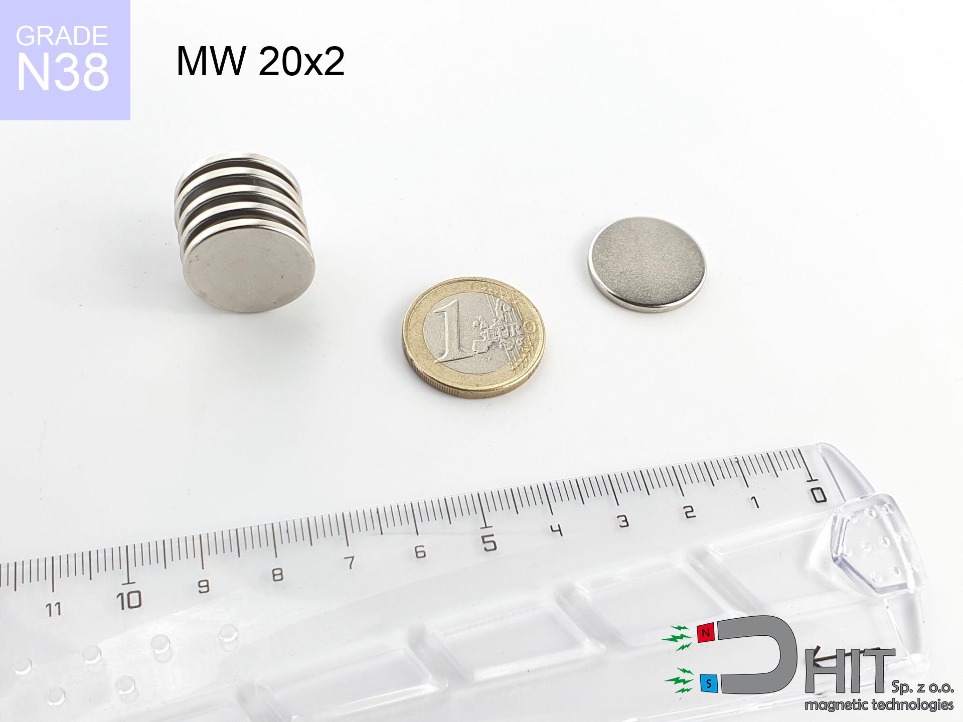
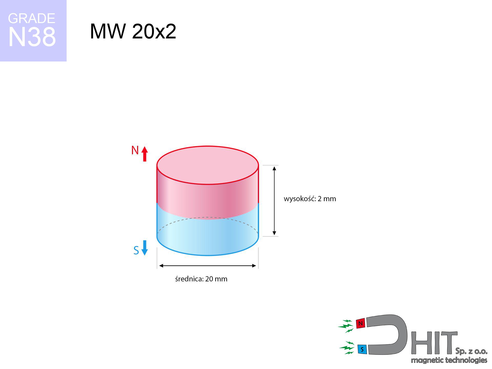
MW 20x2 / N38 - cylindrical magnet
cylindrical magnet
Catalog no 010041
GTIN/EAN: 5906301810407
- Diameter Ø
- 20 mm [±0,1 mm]
- Height
- 2 mm [±0,1 mm]
- Weight
- 4.71 g
- Magnetization Direction
- ↑ axial
- Coating
- [NiCuNi] Nickel
How we measure these parameters — certificates and measurements
1.690 zł net / pcs
2.08 zł with VAT (23% VAT) / pcs
bulk discounts:
Need more?Frequently asked questions
Where can I buy strong cylindrical neodymium magnets?
Can a small cylindrical magnet provide a strong grip for precise workshop work?
Which cylindrical magnet can work at a higher temperature?
Engineering report for this magnet
Full PDF analysis: pull and shear force, effect of distance, temperature and plate thickness, safety distances and the demagnetization curve.
Call us now
+48 888 99 98 98
alternatively let us know using
contact form
the contact section.
Specifications and structure of a neodymium magnet can be estimated using our
power calculator.
Order by 14:00 and we’ll ship today!
Technical - MW 20x2 / N38 - cylindrical magnet
Specification / characteristics - MW 20x2 / N38 - cylindrical magnet
| properties | values |
|---|---|
| Cat. no. | 010041 |
| GTIN/EAN | 5906301810407 |
| Production/Distribution | Dhit sp. z o.o. |
| Country of origin | Poland / China / Germany |
| Customs code | 85059029 |
| Diameter Ø | 20 mm [±0,1 mm] |
| Height | 2 mm [±0,1 mm] |
| Weight | 4.71 g |
| Magnetization Direction | ↑ axial |
| Load capacity ~ ? | 1.63 kg / 15.98 N |
| Magnetic Induction ~ ? | 121.57 mT / 1216 Gs |
| Coating | [NiCuNi] Nickel |
| Manufacturing Tolerance | ±0.1 mm |
Magnetic properties of material N38
| properties | values | units |
|---|---|---|
| Remanence Br ? | 12.2-12.6 | kGs |
| Remanence Br ? | 1220-1260 | mT |
| Coercivity bHc ? | 10.8-11.5 | kOe |
| Coercivity bHc ? | 860-915 | kA/m |
| Intrinsic coercivity iHc | ≥ 12 | kOe |
| Intrinsic coercivity iHc | ≥ 955 | kA/m |
| Energy product BHmax ? | 36-38 | BH max MGOe |
| Energy product BHmax ? | 287-303 | BH max KJ/m |
| Maximum working temperature ? | ≤ 80 | °C |
Physical properties of sintered neodymium magnets Nd2Fe14B at 20°C
| properties | values | units |
|---|---|---|
| Vickers hardness | ≥550 | Hv |
| Density | ≥7.4 | g/cm3 |
| Curie Temperature TC | 310 | °C |
| Curie Temperature TF | 590 | °F |
| Specific resistance | 150 | μΩ⋅cm |
| Bending strength | 250 | MPa |
| Compressive strength | 1000~1100 | MPa |
| Thermal expansion parallel (∥) to orientation (M) | (3-4) x 10-6 | °C-1 |
| Thermal expansion perpendicular (⊥) to orientation (M) | -(1-3) x 10-6 | °C-1 |
| Young's modulus | 1.7 x 10⁴ | kg/mm² |
Engineering analysis of the magnet - data
These information represent the result of a mathematical calculation. Results were calculated on algorithms for the material Nd2Fe14B. Real-world conditions may differ from theoretical values. Treat these calculations as a reference point for designers.
Table 1: Static pull force (pull vs distance) - characteristics
MW 20x2 / N38
| Distance (mm) | Induction (Gauss) / mT | Pull Force (kg/lbs/g/N) | Risk Status |
|---|---|---|---|
| 0 mm |
1216 Gs
121.6 mT
|
1.63 kg / 3.59 pounds
1630.0 g / 16.0 N
|
weak grip |
| 1 mm |
1165 Gs
116.5 mT
|
1.50 kg / 3.30 pounds
1496.3 g / 14.7 N
|
weak grip |
| 2 mm |
1087 Gs
108.7 mT
|
1.30 kg / 2.87 pounds
1302.7 g / 12.8 N
|
weak grip |
| 3 mm |
991 Gs
99.1 mT
|
1.08 kg / 2.39 pounds
1083.7 g / 10.6 N
|
weak grip |
| 5 mm |
783 Gs
78.3 mT
|
0.68 kg / 1.49 pounds
675.9 g / 6.6 N
|
weak grip |
| 10 mm |
379 Gs
37.9 mT
|
0.16 kg / 0.35 pounds
158.4 g / 1.6 N
|
weak grip |
| 15 mm |
185 Gs
18.5 mT
|
0.04 kg / 0.08 pounds
37.9 g / 0.4 N
|
weak grip |
| 20 mm |
99 Gs
9.9 mT
|
0.01 kg / 0.02 pounds
10.8 g / 0.1 N
|
weak grip |
| 30 mm |
36 Gs
3.6 mT
|
0.00 kg / 0.00 pounds
1.4 g / 0.0 N
|
weak grip |
| 50 mm |
9 Gs
0.9 mT
|
0.00 kg / 0.00 pounds
0.1 g / 0.0 N
|
weak grip |
Table 2: Shear hold (vertical surface)
MW 20x2 / N38
| Distance (mm) | Friction coefficient | Pull Force (kg/lbs/g/N) |
|---|---|---|
| 0 mm | Raw steel (µ ≈ 0.2) |
0.33 kg / 0.72 pounds
326.0 g / 3.2 N
|
| 1 mm | Raw steel (µ ≈ 0.2) |
0.30 kg / 0.66 pounds
300.0 g / 2.9 N
|
| 2 mm | Raw steel (µ ≈ 0.2) |
0.26 kg / 0.57 pounds
260.0 g / 2.6 N
|
| 3 mm | Raw steel (µ ≈ 0.2) |
0.22 kg / 0.48 pounds
216.0 g / 2.1 N
|
| 5 mm | Raw steel (µ ≈ 0.2) |
0.14 kg / 0.30 pounds
136.0 g / 1.3 N
|
| 10 mm | Raw steel (µ ≈ 0.2) |
0.03 kg / 0.07 pounds
32.0 g / 0.3 N
|
| 15 mm | Raw steel (µ ≈ 0.2) |
0.01 kg / 0.02 pounds
8.0 g / 0.1 N
|
| 20 mm | Raw steel (µ ≈ 0.2) |
0.00 kg / 0.00 pounds
2.0 g / 0.0 N
|
| 30 mm | Raw steel (µ ≈ 0.2) |
0.00 kg / 0.00 pounds
0.0 g / 0.0 N
|
| 50 mm | Raw steel (µ ≈ 0.2) |
0.00 kg / 0.00 pounds
0.0 g / 0.0 N
|
Table 3: Wall mounting (sliding) - vertical pull
MW 20x2 / N38
| Surface type | Friction coefficient / % | Max load (kg/lbs/g/N) |
|---|---|---|
| Raw steel |
µ = 0.3
30% of nominal force
|
0.49 kg / 1.08 pounds
489.0 g / 4.8 N
|
| Painted steel (standard) |
µ = 0.2
20% of nominal force
|
0.33 kg / 0.72 pounds
326.0 g / 3.2 N
|
| Oily/slippery steel |
µ = 0.1
10% of nominal force
|
0.16 kg / 0.36 pounds
163.0 g / 1.6 N
|
| Magnet with anti-slip rubber |
µ = 0.5
50% of nominal force
|
0.82 kg / 1.80 pounds
815.0 g / 8.0 N
|
Table 4: Material efficiency (saturation) - power losses
MW 20x2 / N38
| Steel thickness (mm) | % power | Real pull force (kg/lbs/g/N) |
|---|---|---|
| 0.5 mm |
|
0.16 kg / 0.36 pounds
163.0 g / 1.6 N
|
| 1 mm |
|
0.41 kg / 0.90 pounds
407.5 g / 4.0 N
|
| 2 mm |
|
0.82 kg / 1.80 pounds
815.0 g / 8.0 N
|
| 3 mm |
|
1.22 kg / 2.70 pounds
1222.5 g / 12.0 N
|
| 5 mm |
|
1.63 kg / 3.59 pounds
1630.0 g / 16.0 N
|
| 10 mm |
|
1.63 kg / 3.59 pounds
1630.0 g / 16.0 N
|
| 11 mm |
|
1.63 kg / 3.59 pounds
1630.0 g / 16.0 N
|
| 12 mm |
|
1.63 kg / 3.59 pounds
1630.0 g / 16.0 N
|
Table 5: Thermal resistance (stability) - thermal limit
MW 20x2 / N38
| Magnet temperature (°C) | Force change relative to 20°C | Remaining pull (kg/lbs/g/N) | Status |
|---|---|---|---|
| 20 °C | 0.0% |
1.63 kg / 3.59 pounds
1630.0 g / 16.0 N
|
Estimate |
| 40 °C | -4.4% |
1.56 kg / 3.44 pounds
1559.1 g / 15.3 N
|
Estimate |
| 60 °C | -8.6% |
1.49 kg / 3.28 pounds
1489.7 g / 14.6 N
|
Estimate |
| 80 °C | -12.8% |
1.42 kg / 3.13 pounds
1421.9 g / 13.9 N
|
Material limit |
| 100 °C | — | — | Out of range — no model |
Table 6: Magnet-Magnet interaction (repulsion) - field collision
MW 20x2 / N38
| Gap (mm) | Attraction (kg/lbs) (N-S) | Shear Strength (kg/lbs/g/N) | Repulsion (kg/lbs) (N-N) |
|---|---|---|---|
| 0 mm |
2.86 kg / 6.31 pounds
2 301 Gs
|
0.43 kg / 0.95 pounds
429 g / 4.2 N
|
N/A |
| 1 mm |
2.76 kg / 6.09 pounds
2 388 Gs
|
0.41 kg / 0.91 pounds
414 g / 4.1 N
|
2.49 kg / 5.48 pounds
~0 Gs
|
| 2 mm |
2.63 kg / 5.79 pounds
2 329 Gs
|
0.39 kg / 0.87 pounds
394 g / 3.9 N
|
2.36 kg / 5.21 pounds
~0 Gs
|
| 3 mm |
2.47 kg / 5.44 pounds
2 257 Gs
|
0.37 kg / 0.82 pounds
370 g / 3.6 N
|
2.22 kg / 4.89 pounds
~0 Gs
|
| 5 mm |
2.10 kg / 4.62 pounds
2 081 Gs
|
0.31 kg / 0.69 pounds
315 g / 3.1 N
|
1.89 kg / 4.16 pounds
~0 Gs
|
| 10 mm |
1.19 kg / 2.62 pounds
1 565 Gs
|
0.18 kg / 0.39 pounds
178 g / 1.7 N
|
1.07 kg / 2.35 pounds
~0 Gs
|
| 20 mm |
0.28 kg / 0.61 pounds
758 Gs
|
0.04 kg / 0.09 pounds
42 g / 0.4 N
|
0.25 kg / 0.55 pounds
~0 Gs
|
| 50 mm |
0.01 kg / 0.01 pounds
115 Gs
|
0.00 kg / 0.00 pounds
1 g / 0.0 N
|
0.00 kg / 0.00 pounds
~0 Gs
|
| 60 mm |
0.00 kg / 0.01 pounds
72 Gs
|
0.00 kg / 0.00 pounds
0 g / 0.0 N
|
0.00 kg / 0.00 pounds
~0 Gs
|
| 70 mm |
0.00 kg / 0.00 pounds
48 Gs
|
0.00 kg / 0.00 pounds
0 g / 0.0 N
|
0.00 kg / 0.00 pounds
~0 Gs
|
| 80 mm |
0.00 kg / 0.00 pounds
33 Gs
|
0.00 kg / 0.00 pounds
0 g / 0.0 N
|
0.00 kg / 0.00 pounds
~0 Gs
|
| 90 mm |
0.00 kg / 0.00 pounds
24 Gs
|
0.00 kg / 0.00 pounds
0 g / 0.0 N
|
0.00 kg / 0.00 pounds
~0 Gs
|
| 100 mm |
0.00 kg / 0.00 pounds
18 Gs
|
0.00 kg / 0.00 pounds
0 g / 0.0 N
|
0.00 kg / 0.00 pounds
~0 Gs
|
Table 7: Axial field levels — not safety zones
MW 20x2 / N38
| Field level (Gs) | mT | Model distance (cm) |
|---|---|---|
| < 5 Gs | < 0.5 mT | 6.5 cm |
| < 10 Gs | < 1.0 mT | 5.0 cm |
| < 20 Gs | < 2.0 mT | 4.0 cm |
| < 40 Gs | < 4.0 mT | 3.0 cm |
| < 50 Gs | < 5.0 mT | 3.0 cm |
| < 400 Gs | < 40.0 mT | 1.0 cm |
| < 600 Gs | < 60.0 mT | 1.0 cm |
Table 8: Impact energy (kinetic energy) - warning
MW 20x2 / N38
| Start from (mm) | Speed (km/h) | Energy (J) | Predicted outcome |
|---|---|---|---|
| 10 mm |
20.42 km/h
(5.67 m/s)
|
0.08 J | |
| 30 mm |
21.15 km/h
(5.88 m/s)
|
0.08 J | |
| 50 mm |
21.16 km/h
(5.88 m/s)
|
0.08 J | |
| 100 mm |
21.16 km/h
(5.88 m/s)
|
0.08 J |
Table 9: Anti-corrosion coating durability
MW 20x2 / N38
| Technical parameter | Value / Description |
|---|---|
| Coating type | [NiCuNi] Nickel |
| Layer structure | Nickel - Copper - Nickel |
| Layer thickness | 10-20 µm |
| Salt spray test (SST) ? | 24 h |
| Recommended environment | Indoors only (dry) |
Table 10: Construction data (Pc)
MW 20x2 / N38
| Parameter | Value | SI Unit / Description |
|---|---|---|
| Magnetic Flux | 5 038 Mx | 50.4 µWb |
| Pc Coefficient | 0.16 | Low (Flat) |
Table 11: Physics of underwater searching
MW 20x2 / N38
| Environment | Effective steel pull | Effect |
|---|---|---|
| Air (land) | 1.63 kg | Standard |
| Water (riverbed) |
1.87 kg
(+0.24 kg buoyancy gain)
|
+14.5% |
1. Wall mount (shear)
*Caution: On a vertical wall, the magnet retains only approx. 20-30% of its perpendicular strength.
2. Steel saturation
*Thin steel (e.g. 0.5mm PC case) severely weakens the holding force.
3. Thermal stability
N38: the maximum material working temperature is 80°C. Permitted conditions also depend on the shape and magnetic circuit.
4. Demagnetization curve and operating point (B-H)
chart generated for the permeance coefficient Pc (Permeance Coefficient) = 0.16
The chart above illustrates the magnetic characteristics of the material within the second quadrant of the hysteresis loop. The solid red line represents the demagnetization curve (material potential), while the dashed blue line is the load line based on the magnet's geometry. The Pc (Permeance Coefficient), also known as the load line slope, is a dimensionless value that describes the relationship between the magnet's shape and its magnetic stability. The intersection of these two lines (the black dot) is the operating point — it determines the actual magnetic flux density generated by the magnet in this specific configuration. A higher Pc value means the magnet is more 'slender' (tall relative to its area), resulting in a higher operating point and better resistance to irreversible demagnetization caused by external fields or temperature. A value of 0.42 is relatively low (typical for flat magnets), meaning the operating point is closer to the 'knee' of the curve — caution is advised when operating at temperatures near the maximum limit to avoid strength loss.
Elemental analysis
| iron (Fe) | 64% – 68% |
| neodymium (Nd) | 29% – 32% |
| boron (B) | 1.1% – 1.2% |
| dysprosium (Dy) | 0.5% – 2.0% |
| coating (Ni-Cu-Ni) | < 0.05% |
Environmental data
| recyclability (EoL) | 100% |
| recycled raw materials | ~10% (pre-cons) |
| carbon footprint | low / zredukowany |
| waste code (EWC) | 16 02 16 |
Other offers
![UMH 60x15x69 [M8] / N38 - magnetic holder with hook](https://cdn3.dhit.pl/graphics/products/umh-60x15x69-m8-nij.jpg "UMH 60x15x69 [M8] / N38 - magnetic holder with hook")
Advantages as well as disadvantages of Nd2Fe14B magnets.
Strengths
- They retain magnetic properties for nearly ten years – the loss is just ~1% (in theory),
- Neodymium magnets are characterized by remarkably resistant to magnetic field loss caused by external interference,
- The use of an aesthetic finish of noble metals (nickel, gold, silver) causes the element to be more visually attractive,
- The surface of neodymium magnets generates a powerful magnetic field – this is one of their assets,
- Through (appropriate) combination of ingredients, they can achieve high thermal strength, allowing for operation at temperatures reaching 230°C and above...
- Thanks to modularity in constructing and the ability to customize to complex applications,
- Universal use in advanced technology sectors – they are utilized in computer drives, electric motors, diagnostic systems, as well as complex engineering applications.
- Thanks to their power density, small magnets offer high operating force, in miniature format,
Weaknesses
- Susceptibility to cracking is one of their disadvantages. Upon intense impact they can break. We recommend keeping them in a special holder, which not only secures them against impacts but also raises their durability
- Do not exceed this material temperature limit: 80°C. Overheating may permanently weaken the magnet.
- They oxidize in a humid environment. For use outdoors we suggest using waterproof magnets e.g. in rubber, plastic
- Due to limitations in realizing threads and complex shapes in magnets, we propose using casing - magnetic mechanism.
- Possible danger to health – tiny shards of magnets pose a threat, in case of ingestion, which gains importance in the context of child safety. It is also worth noting that small components of these magnets can disrupt the diagnostic process medical in case of swallowing.
- Higher cost of purchase is one of the disadvantages compared to ceramic magnets, especially in budget applications
Holding force characteristics
Highest magnetic holding force – what contributes to it?
- using a sheet made of low-carbon steel, acting as a magnetic yoke
- whose transverse dimension equals approx. 10 mm
- characterized by smoothness
- under conditions of ideal adhesion (surface-to-surface)
- for force applied at a right angle (pull-off, not shear)
- at temperature room level
Determinants of practical lifting force of a magnet
- Distance (betwixt the magnet and the plate), because even a tiny clearance (e.g. 0.5 mm) can cause a reduction in force by up to 50% (this also applies to paint, corrosion or dirt).
- Angle of force application – maximum parameter is obtained only during pulling at a 90° angle. The force required to slide of the magnet along the plate is standardly many times smaller (approx. 1/5 of the lifting capacity).
- Substrate thickness – for full efficiency, the steel must be sufficiently thick. Thin sheet restricts the attraction force (the magnet "punches through" it).
- Material composition – not every steel reacts the same. Alloy additives worsen the interaction with the magnet.
- Plate texture – smooth surfaces ensure maximum contact, which increases force. Rough surfaces reduce efficiency.
- Thermal environment – heating the magnet results in weakening of force. It is worth remembering the thermal limit for a given model.
Holding force was measured on a smooth steel plate of 20 mm thickness, when the force acted perpendicularly, in contrast under attempts to slide the magnet the load capacity is reduced by as much as 75%. In addition, even a minimal clearance between the magnet and the plate lowers the lifting capacity.
H&S for magnets
Keep away from electronics
Note: rare earth magnets generate a field that confuses precision electronics. Keep a separation from your mobile, device, and navigation systems.
ICD Warning
People with a pacemaker should keep an large gap from magnets. The magnetism can stop the operation of the life-saving device.
Skin irritation risks
A percentage of the population suffer from a sensitization to nickel, which is the typical protective layer for NdFeB magnets. Frequent touching can result in dermatitis. We suggest use protective gloves.
Permanent damage
Do not exceed the maximum operating temperature stated in the specifications of the particular product. The limit depends on the material, geometry and operating arrangement; there is no single threshold for all neodymium magnets. Overheating can permanently weaken a magnet.
Beware of splinters
Beware of splinters. Magnets can fracture upon violent connection, launching shards into the air. Eye protection is mandatory.
Electronic hazard
Device Safety: Neodymium magnets can ruin payment cards and sensitive devices (pacemakers, medical aids, mechanical watches).
Dust explosion hazard
Powder created during cutting of magnets is flammable. Avoid drilling into magnets unless you are an expert.
Handling guide
Handle magnets with awareness. Their huge power can shock even professionals. Plan your moves and respect their power.
Choking Hazard
These products are not toys. Eating multiple magnets can lead to them connecting inside the digestive tract, which poses a critical condition and necessitates immediate surgery.
Physical harm
Watch your fingers. Two powerful magnets will join immediately with a force of several hundred kilograms, destroying everything in their path. Exercise extreme caution!
Tabela kosztu i czasu dostawy
Płatność przed wysyłką:

GLS kurier
Przesyłka będzie u Ciebie za 2-3 dni
14.99 ZŁ

InPost Paczkomaty 24/7
Przesyłka będzie u Ciebie za 1-2 dni
12.30 ZŁ
Płatność przy odbiorze (pobranie):
GLS kurier
Przesyłka będzie u Ciebie za 1-2 dni
23.00 ZŁ