
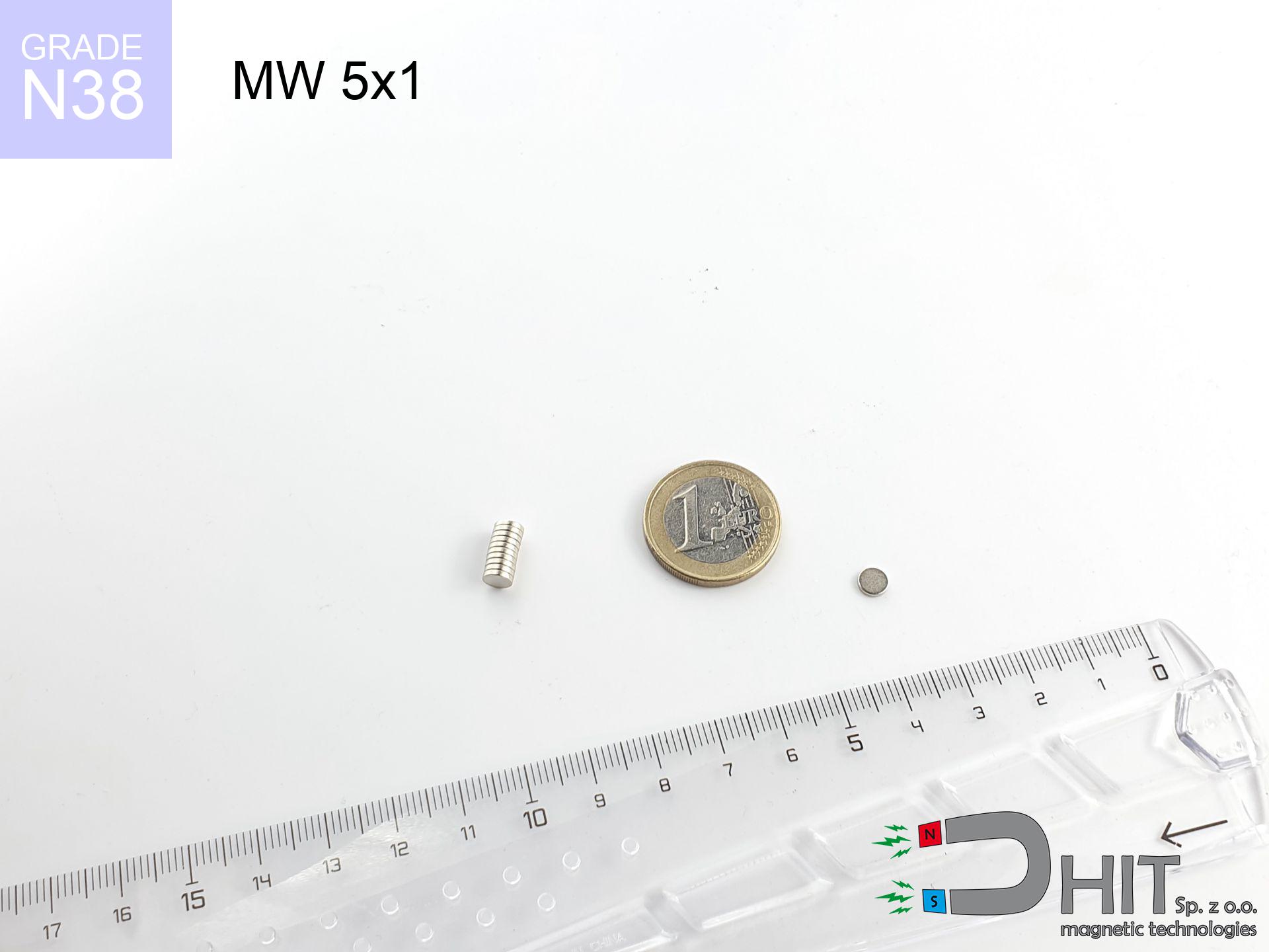
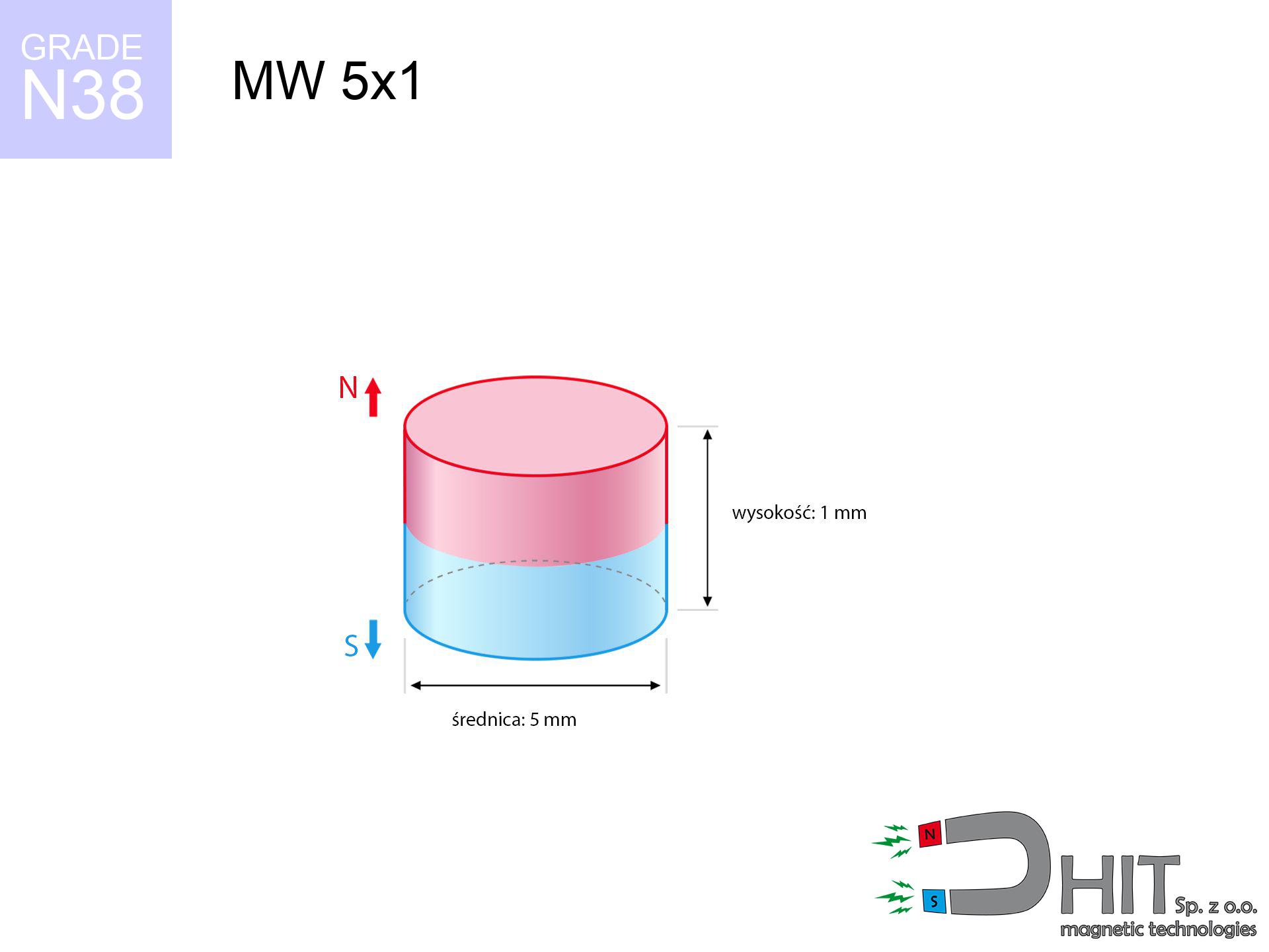
MW 5x1 / N38 - cylindrical magnet
cylindrical magnet
Catalog no 010082
GTIN/EAN: 5906301810810
Diameter Ø
5 mm [±0,1 mm]
Height
1 mm [±0,1 mm]
Weight
0.15 g
Magnetization Direction
↑ axial
Load capacity
0.32 kg / 3.12 N
Magnetic Induction
229.95 mT / 2300 Gs
Coating
[NiCuNi] Nickel
0.1845 ZŁ with VAT / pcs + price for transport
0.1500 ZŁ net + 23% VAT / pcs
bulk discounts:
Need more?
Contact us by phone
+48 22 499 98 98
if you prefer get in touch using
our online form
the contact page.
Strength and form of neodymium magnets can be estimated with our
online calculation tool.
Orders placed before 14:00 will be shipped the same business day.
Technical data of the product - MW 5x1 / N38 - cylindrical magnet
Specification / characteristics - MW 5x1 / N38 - cylindrical magnet
| properties | values |
|---|---|
| Cat. no. | 010082 |
| GTIN/EAN | 5906301810810 |
| Production/Distribution | Dhit sp. z o.o. |
| Country of origin | Poland / China / Germany |
| Customs code | 85059029 |
| Diameter Ø | 5 mm [±0,1 mm] |
| Height | 1 mm [±0,1 mm] |
| Weight | 0.15 g |
| Magnetization Direction | ↑ axial |
| Load capacity ~ ? | 0.32 kg / 3.12 N |
| Magnetic Induction ~ ? | 229.95 mT / 2300 Gs |
| Coating | [NiCuNi] Nickel |
| Manufacturing Tolerance | ±0.1 mm |
Magnetic properties of material N38
| properties | values | units |
|---|---|---|
| remenance Br [min. - max.] ? | 12.2-12.6 | kGs |
| remenance Br [min. - max.] ? | 1220-1260 | mT |
| coercivity bHc ? | 10.8-11.5 | kOe |
| coercivity bHc ? | 860-915 | kA/m |
| actual internal force iHc | ≥ 12 | kOe |
| actual internal force iHc | ≥ 955 | kA/m |
| energy density [min. - max.] ? | 36-38 | BH max MGOe |
| energy density [min. - max.] ? | 287-303 | BH max KJ/m |
| max. temperature ? | ≤ 80 | °C |
Physical properties of sintered neodymium magnets Nd2Fe14B at 20°C
| properties | values | units |
|---|---|---|
| Vickers hardness | ≥550 | Hv |
| Density | ≥7.4 | g/cm3 |
| Curie Temperature TC | 312 - 380 | °C |
| Curie Temperature TF | 593 - 716 | °F |
| Specific resistance | 150 | μΩ⋅cm |
| Bending strength | 250 | MPa |
| Compressive strength | 1000~1100 | MPa |
| Thermal expansion parallel (∥) to orientation (M) | (3-4) x 10-6 | °C-1 |
| Thermal expansion perpendicular (⊥) to orientation (M) | -(1-3) x 10-6 | °C-1 |
| Young's modulus | 1.7 x 10⁴ | kg/mm² |
Technical analysis of the assembly - report
Presented information are the outcome of a engineering simulation. Values rely on models for the material Nd2Fe14B. Real-world parameters might slightly differ. Treat these calculations as a reference point for designers.
Table 1: Static pull force (force vs distance) - characteristics
MW 5x1 / N38
| Distance (mm) | Induction (Gauss) / mT | Pull Force (kg/lbs/g/N) | Risk Status |
|---|---|---|---|
| 0 mm |
2298 Gs
229.8 mT
|
0.32 kg / 0.71 lbs
320.0 g / 3.1 N
|
low risk |
| 1 mm |
1570 Gs
157.0 mT
|
0.15 kg / 0.33 lbs
149.5 g / 1.5 N
|
low risk |
| 2 mm |
890 Gs
89.0 mT
|
0.05 kg / 0.11 lbs
48.0 g / 0.5 N
|
low risk |
| 3 mm |
495 Gs
49.5 mT
|
0.01 kg / 0.03 lbs
14.8 g / 0.1 N
|
low risk |
| 5 mm |
178 Gs
17.8 mT
|
0.00 kg / 0.00 lbs
1.9 g / 0.0 N
|
low risk |
| 10 mm |
31 Gs
3.1 mT
|
0.00 kg / 0.00 lbs
0.1 g / 0.0 N
|
low risk |
| 15 mm |
10 Gs
1.0 mT
|
0.00 kg / 0.00 lbs
0.0 g / 0.0 N
|
low risk |
| 20 mm |
4 Gs
0.4 mT
|
0.00 kg / 0.00 lbs
0.0 g / 0.0 N
|
low risk |
| 30 mm |
1 Gs
0.1 mT
|
0.00 kg / 0.00 lbs
0.0 g / 0.0 N
|
low risk |
| 50 mm |
0 Gs
0.0 mT
|
0.00 kg / 0.00 lbs
0.0 g / 0.0 N
|
low risk |
Table 2: Vertical load (wall)
MW 5x1 / N38
| Distance (mm) | Friction coefficient | Pull Force (kg/lbs/g/N) |
|---|---|---|
| 0 mm | Stal (~0.2) |
0.06 kg / 0.14 lbs
64.0 g / 0.6 N
|
| 1 mm | Stal (~0.2) |
0.03 kg / 0.07 lbs
30.0 g / 0.3 N
|
| 2 mm | Stal (~0.2) |
0.01 kg / 0.02 lbs
10.0 g / 0.1 N
|
| 3 mm | Stal (~0.2) |
0.00 kg / 0.00 lbs
2.0 g / 0.0 N
|
| 5 mm | Stal (~0.2) |
0.00 kg / 0.00 lbs
0.0 g / 0.0 N
|
| 10 mm | Stal (~0.2) |
0.00 kg / 0.00 lbs
0.0 g / 0.0 N
|
| 15 mm | Stal (~0.2) |
0.00 kg / 0.00 lbs
0.0 g / 0.0 N
|
| 20 mm | Stal (~0.2) |
0.00 kg / 0.00 lbs
0.0 g / 0.0 N
|
| 30 mm | Stal (~0.2) |
0.00 kg / 0.00 lbs
0.0 g / 0.0 N
|
| 50 mm | Stal (~0.2) |
0.00 kg / 0.00 lbs
0.0 g / 0.0 N
|
Table 3: Wall mounting (sliding) - behavior on slippery surfaces
MW 5x1 / N38
| Surface type | Friction coefficient / % Mocy | Max load (kg/lbs/g/N) |
|---|---|---|
| Raw steel |
µ = 0.3
30% Nominalnej Siły
|
0.10 kg / 0.21 lbs
96.0 g / 0.9 N
|
| Painted steel (standard) |
µ = 0.2
20% Nominalnej Siły
|
0.06 kg / 0.14 lbs
64.0 g / 0.6 N
|
| Oily/slippery steel |
µ = 0.1
10% Nominalnej Siły
|
0.03 kg / 0.07 lbs
32.0 g / 0.3 N
|
| Magnet with anti-slip rubber |
µ = 0.5
50% Nominalnej Siły
|
0.16 kg / 0.35 lbs
160.0 g / 1.6 N
|
Table 4: Steel thickness (substrate influence) - sheet metal selection
MW 5x1 / N38
| Steel thickness (mm) | % power | Real pull force (kg/lbs/g/N) |
|---|---|---|
| 0.5 mm |
|
0.03 kg / 0.07 lbs
32.0 g / 0.3 N
|
| 1 mm |
|
0.08 kg / 0.18 lbs
80.0 g / 0.8 N
|
| 2 mm |
|
0.16 kg / 0.35 lbs
160.0 g / 1.6 N
|
| 3 mm |
|
0.24 kg / 0.53 lbs
240.0 g / 2.4 N
|
| 5 mm |
|
0.32 kg / 0.71 lbs
320.0 g / 3.1 N
|
| 10 mm |
|
0.32 kg / 0.71 lbs
320.0 g / 3.1 N
|
| 11 mm |
|
0.32 kg / 0.71 lbs
320.0 g / 3.1 N
|
| 12 mm |
|
0.32 kg / 0.71 lbs
320.0 g / 3.1 N
|
Table 5: Working in heat (material behavior) - power drop
MW 5x1 / N38
| Ambient temp. (°C) | Power loss | Remaining pull (kg/lbs/g/N) | Status |
|---|---|---|---|
| 20 °C | 0.0% |
0.32 kg / 0.71 lbs
320.0 g / 3.1 N
|
OK |
| 40 °C | -2.2% |
0.31 kg / 0.69 lbs
313.0 g / 3.1 N
|
OK |
| 60 °C | -4.4% |
0.31 kg / 0.67 lbs
305.9 g / 3.0 N
|
|
| 80 °C | -6.6% |
0.30 kg / 0.66 lbs
298.9 g / 2.9 N
|
|
| 100 °C | -28.8% |
0.23 kg / 0.50 lbs
227.8 g / 2.2 N
|
Table 6: Two magnets (attraction) - forces in the system
MW 5x1 / N38
| Gap (mm) | Attraction (kg/lbs) (N-S) | Shear Strength (kg/lbs/g/N) | Repulsion (kg/lbs) (N-N) |
|---|---|---|---|
| 0 mm |
0.64 kg / 1.41 lbs
3 860 Gs
|
0.10 kg / 0.21 lbs
96 g / 0.9 N
|
N/A |
| 1 mm |
0.47 kg / 1.04 lbs
3 948 Gs
|
0.07 kg / 0.16 lbs
71 g / 0.7 N
|
0.42 kg / 0.94 lbs
~0 Gs
|
| 2 mm |
0.30 kg / 0.66 lbs
3 141 Gs
|
0.04 kg / 0.10 lbs
45 g / 0.4 N
|
0.27 kg / 0.59 lbs
~0 Gs
|
| 3 mm |
0.17 kg / 0.38 lbs
2 388 Gs
|
0.03 kg / 0.06 lbs
26 g / 0.3 N
|
0.16 kg / 0.34 lbs
~0 Gs
|
| 5 mm |
0.05 kg / 0.12 lbs
1 322 Gs
|
0.01 kg / 0.02 lbs
8 g / 0.1 N
|
0.05 kg / 0.10 lbs
~0 Gs
|
| 10 mm |
0.00 kg / 0.01 lbs
355 Gs
|
0.00 kg / 0.00 lbs
1 g / 0.0 N
|
0.00 kg / 0.00 lbs
~0 Gs
|
| 20 mm |
0.00 kg / 0.00 lbs
62 Gs
|
0.00 kg / 0.00 lbs
0 g / 0.0 N
|
0.00 kg / 0.00 lbs
~0 Gs
|
| 50 mm |
0.00 kg / 0.00 lbs
5 Gs
|
0.00 kg / 0.00 lbs
0 g / 0.0 N
|
0.00 kg / 0.00 lbs
~0 Gs
|
| 60 mm |
0.00 kg / 0.00 lbs
3 Gs
|
0.00 kg / 0.00 lbs
0 g / 0.0 N
|
0.00 kg / 0.00 lbs
~0 Gs
|
| 70 mm |
0.00 kg / 0.00 lbs
2 Gs
|
0.00 kg / 0.00 lbs
0 g / 0.0 N
|
0.00 kg / 0.00 lbs
~0 Gs
|
| 80 mm |
0.00 kg / 0.00 lbs
1 Gs
|
0.00 kg / 0.00 lbs
0 g / 0.0 N
|
0.00 kg / 0.00 lbs
~0 Gs
|
| 90 mm |
0.00 kg / 0.00 lbs
1 Gs
|
0.00 kg / 0.00 lbs
0 g / 0.0 N
|
0.00 kg / 0.00 lbs
~0 Gs
|
| 100 mm |
0.00 kg / 0.00 lbs
1 Gs
|
0.00 kg / 0.00 lbs
0 g / 0.0 N
|
0.00 kg / 0.00 lbs
~0 Gs
|
Table 7: Protective zones (electronics) - warnings
MW 5x1 / N38
| Object / Device | Limit (Gauss) / mT | Safe distance |
|---|---|---|
| Pacemaker | 5 Gs (0.5 mT) | 2.0 cm |
| Hearing aid | 10 Gs (1.0 mT) | 2.0 cm |
| Timepiece | 20 Gs (2.0 mT) | 1.5 cm |
| Phone / Smartphone | 40 Gs (4.0 mT) | 1.0 cm |
| Remote | 50 Gs (5.0 mT) | 1.0 cm |
| Payment card | 400 Gs (40.0 mT) | 0.5 cm |
| HDD hard drive | 600 Gs (60.0 mT) | 0.5 cm |
Table 8: Collisions (kinetic energy) - warning
MW 5x1 / N38
| Start from (mm) | Speed (km/h) | Energy (J) | Predicted outcome |
|---|---|---|---|
| 10 mm |
46.59 km/h
(12.94 m/s)
|
0.01 J | |
| 30 mm |
80.68 km/h
(22.41 m/s)
|
0.04 J | |
| 50 mm |
104.16 km/h
(28.93 m/s)
|
0.06 J | |
| 100 mm |
147.30 km/h
(40.92 m/s)
|
0.13 J |
Table 9: Coating parameters (durability)
MW 5x1 / N38
| Technical parameter | Value / Description |
|---|---|
| Coating type | [NiCuNi] Nickel |
| Layer structure | Nickel - Copper - Nickel |
| Layer thickness | 10-20 µm |
| Salt spray test (SST) ? | 24 h |
| Recommended environment | Indoors only (dry) |
Table 10: Electrical data (Flux)
MW 5x1 / N38
| Parameter | Value | SI Unit / Description |
|---|---|---|
| Magnetic Flux | 524 Mx | 5.2 µWb |
| Pc Coefficient | 0.29 | Low (Flat) |
Table 11: Submerged application
MW 5x1 / N38
| Environment | Effective steel pull | Effect |
|---|---|---|
| Air (land) | 0.32 kg | Standard |
| Water (riverbed) |
0.37 kg
(+0.05 kg buoyancy gain)
|
+14.5% |
1. Sliding resistance
*Note: On a vertical wall, the magnet retains only approx. 20-30% of its perpendicular strength.
2. Plate thickness effect
*Thin metal sheet (e.g. 0.5mm PC case) significantly weakens the holding force.
3. Temperature resistance
*For N38 grade, the critical limit is 80°C.
4. Demagnetization curve and operating point (B-H)
chart generated for the permeance coefficient Pc (Permeance Coefficient) = 0.29
This simulation demonstrates the magnetic stability of the selected magnet under specific geometric conditions. The solid red line represents the demagnetization curve (material potential), while the dashed blue line is the load line based on the magnet's geometry. The Pc (Permeance Coefficient), also known as the load line slope, is a dimensionless value that describes the relationship between the magnet's shape and its magnetic stability. The intersection of these two lines (the black dot) is the operating point — it determines the actual magnetic flux density generated by the magnet in this specific configuration. A higher Pc value means the magnet is more 'slender' (tall relative to its area), resulting in a higher operating point and better resistance to irreversible demagnetization caused by external fields or temperature. A value of 0.42 is relatively low (typical for flat magnets), meaning the operating point is closer to the 'knee' of the curve — caution is advised when operating at temperatures near the maximum limit to avoid strength loss.
Material specification
| iron (Fe) | 64% – 68% |
| neodymium (Nd) | 29% – 32% |
| boron (B) | 1.1% – 1.2% |
| dysprosium (Dy) | 0.5% – 2.0% |
| coating (Ni-Cu-Ni) | < 0.05% |
Sustainability
| recyclability (EoL) | 100% |
| recycled raw materials | ~10% (pre-cons) |
| carbon footprint | low / zredukowany |
| waste code (EWC) | 16 02 16 |
Check out also deals


Strengths as well as weaknesses of rare earth magnets.
Strengths
- They retain full power for around ten years – the loss is just ~1% (according to analyses),
- Neodymium magnets are characterized by extremely resistant to demagnetization caused by external interference,
- A magnet with a smooth gold surface looks better,
- The surface of neodymium magnets generates a concentrated magnetic field – this is a distinguishing feature,
- Through (appropriate) combination of ingredients, they can achieve high thermal resistance, enabling operation at temperatures reaching 230°C and above...
- Possibility of custom modeling as well as optimizing to concrete applications,
- Versatile presence in modern technologies – they serve a role in HDD drives, electromotive mechanisms, diagnostic systems, as well as other advanced devices.
- Thanks to concentrated force, small magnets offer high operating force, in miniature format,
Cons
- At strong impacts they can break, therefore we recommend placing them in steel cases. A metal housing provides additional protection against damage and increases the magnet's durability.
- Neodymium magnets decrease their force under the influence of heating. As soon as 80°C is exceeded, many of them start losing their force. Therefore, we recommend our special magnets marked [AH], which maintain stability even at temperatures up to 230°C
- They oxidize in a humid environment - during use outdoors we recommend using waterproof magnets e.g. in rubber, plastic
- Due to limitations in realizing nuts and complex forms in magnets, we recommend using a housing - magnetic holder.
- Potential hazard resulting from small fragments of magnets can be dangerous, in case of ingestion, which becomes key in the context of child health protection. Furthermore, small components of these magnets can complicate diagnosis medical after entering the body.
- With mass production the cost of neodymium magnets is a challenge,
Pull force analysis
Maximum lifting force for a neodymium magnet – what it depends on?
- on a base made of structural steel, effectively closing the magnetic field
- with a thickness no less than 10 mm
- with a plane cleaned and smooth
- with zero gap (without paint)
- under axial force vector (90-degree angle)
- at temperature approx. 20 degrees Celsius
What influences lifting capacity in practice
- Space between magnet and steel – every millimeter of distance (caused e.g. by veneer or unevenness) significantly weakens the magnet efficiency, often by half at just 0.5 mm.
- Pull-off angle – remember that the magnet has greatest strength perpendicularly. Under shear forces, the holding force drops significantly, often to levels of 20-30% of the nominal value.
- Steel thickness – too thin sheet does not close the flux, causing part of the power to be lost into the air.
- Steel grade – the best choice is pure iron steel. Cast iron may attract less.
- Surface structure – the smoother and more polished the plate, the larger the contact zone and stronger the hold. Roughness creates an air distance.
- Thermal factor – high temperature reduces magnetic field. Exceeding the limit temperature can permanently damage the magnet.
Lifting capacity was measured by applying a steel plate with a smooth surface of optimal thickness (min. 20 mm), under vertically applied force, however under attempts to slide the magnet the lifting capacity is smaller. In addition, even a small distance between the magnet’s surface and the plate lowers the load capacity.
H&S for magnets
Swallowing risk
Adult use only. Tiny parts pose a choking risk, leading to severe trauma. Store out of reach of kids and pets.
Physical harm
Large magnets can break fingers in a fraction of a second. Under no circumstances place your hand between two attracting surfaces.
Caution required
Exercise caution. Rare earth magnets act from a distance and snap with massive power, often faster than you can react.
Combustion hazard
Fire warning: Rare earth powder is explosive. Avoid machining magnets without safety gear as this risks ignition.
Magnets are brittle
Beware of splinters. Magnets can fracture upon uncontrolled impact, ejecting shards into the air. Wear goggles.
Protect data
Device Safety: Neodymium magnets can ruin data carriers and delicate electronics (heart implants, medical aids, mechanical watches).
GPS Danger
Navigation devices and mobile phones are highly sensitive to magnetic fields. Close proximity with a powerful NdFeB magnet can decalibrate the sensors in your phone.
Permanent damage
Avoid heat. NdFeB magnets are sensitive to heat. If you need operation above 80°C, inquire about HT versions (H, SH, UH).
Medical interference
People with a ICD have to keep an safe separation from magnets. The magnetism can interfere with the operation of the life-saving device.
Allergic reactions
Allergy Notice: The Ni-Cu-Ni coating contains nickel. If skin irritation occurs, immediately stop handling magnets and wear gloves.
Tabela kosztu i czasu dostawy
Płatność przed wysyłką:

GLS kurier
Przesyłka będzie u Ciebie za 2-3 dni
14.99 ZŁ

InPost Paczkomaty 24/7
Przesyłka będzie u Ciebie za 1-2 dni
12.30 ZŁ
Płatność przy odbiorze (pobranie):
GLS kurier
Przesyłka będzie u Ciebie za 1-2 dni
23.00 ZŁ
Rate the product
Your rating