

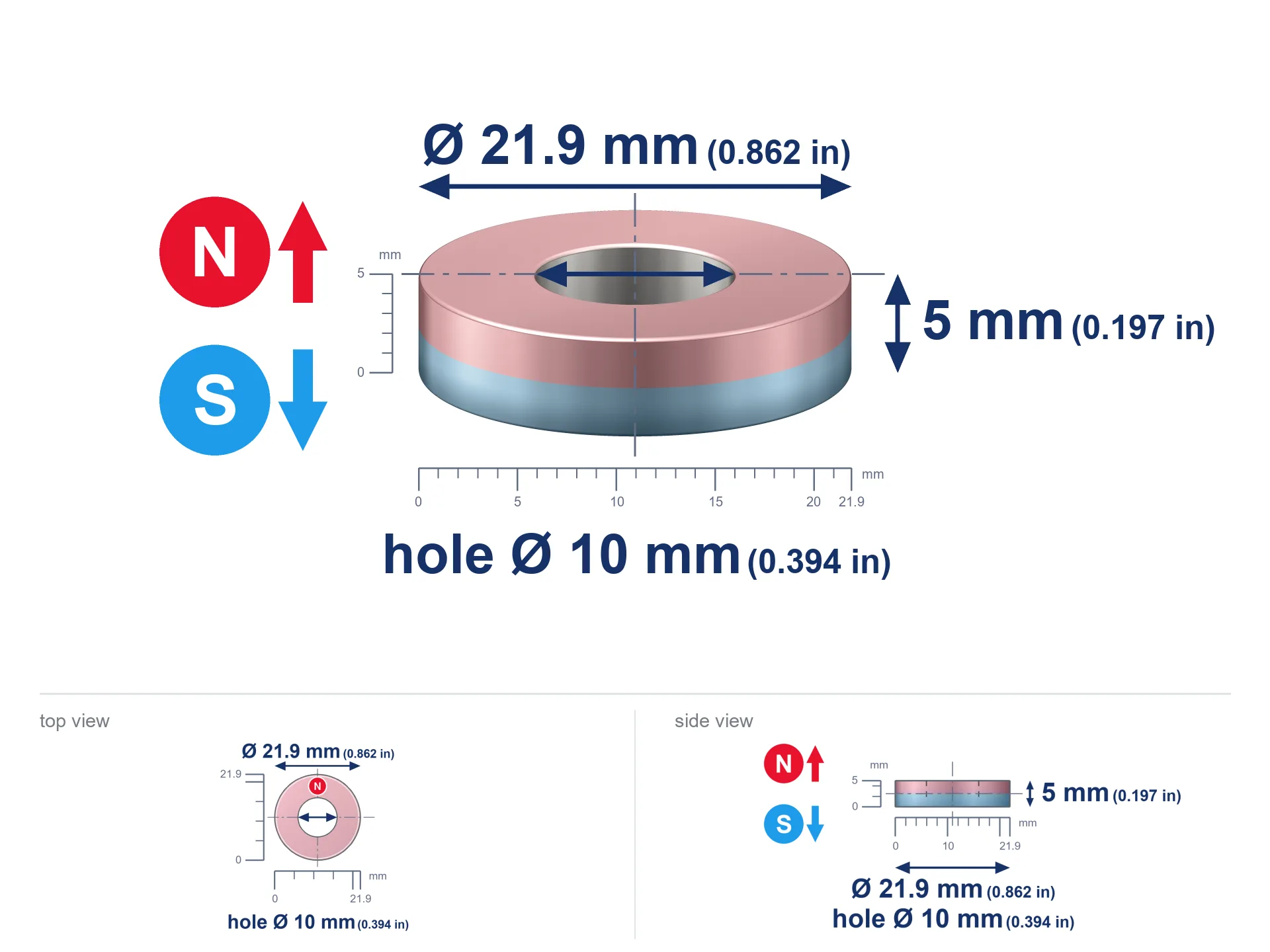
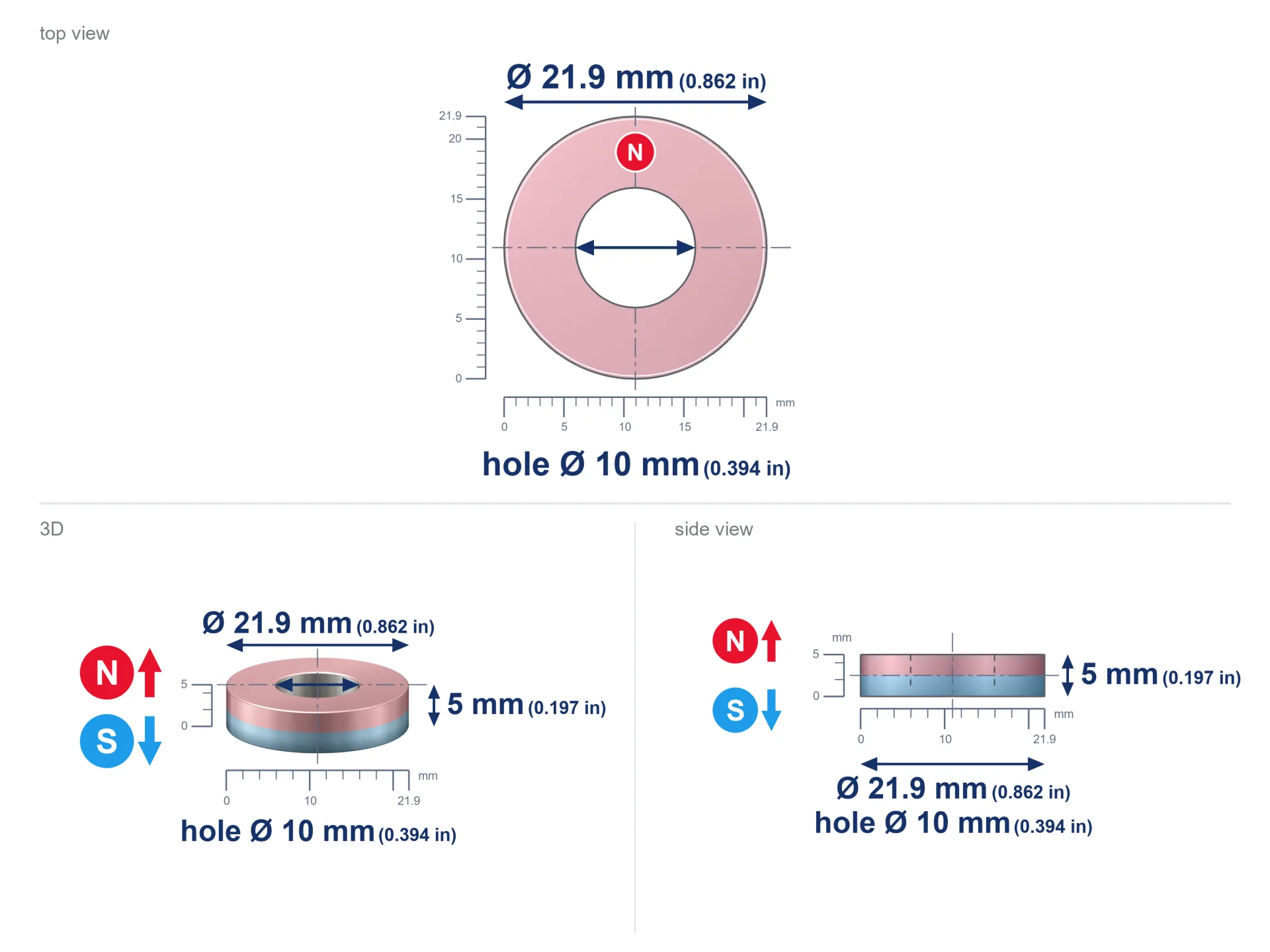
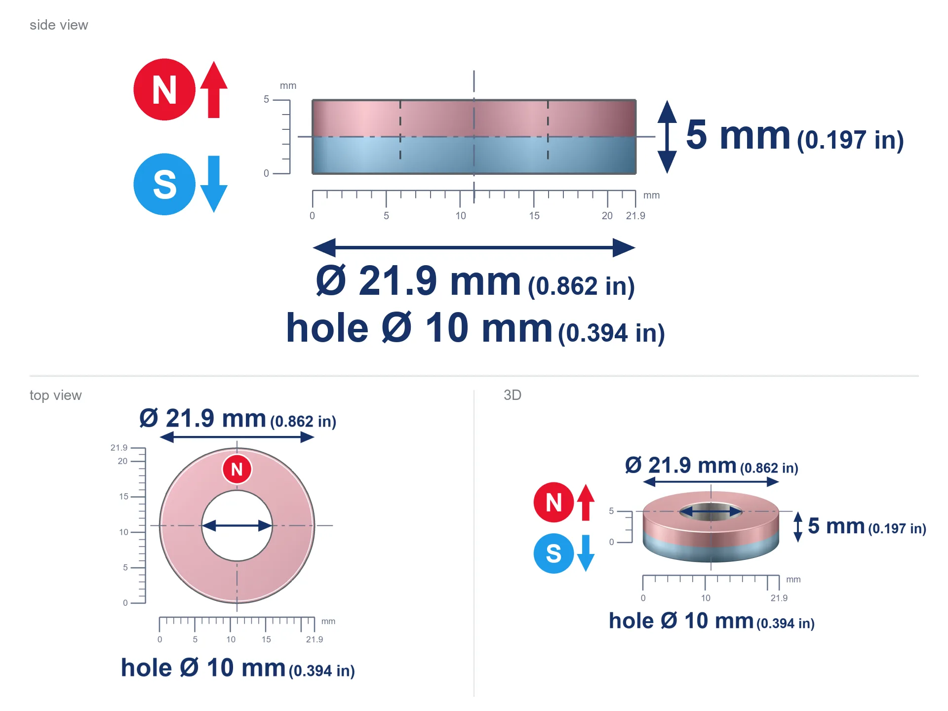
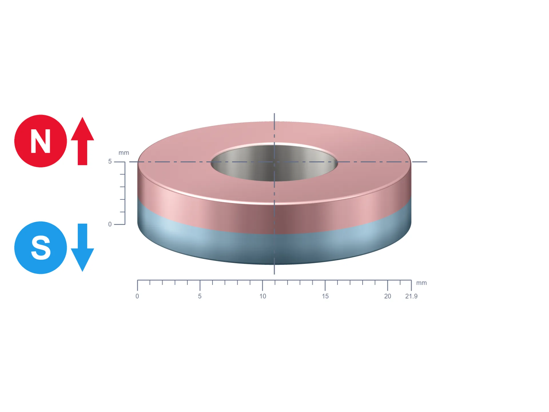
MP 21.9x10x5 / N52 - ring magnet
ring magnet
Catalog no 030598
GTIN/EAN: 5906301816089
- Diameter
- 21.9 mm [±0,1 mm]
- internal diameter Ø
- 10 mm [±0,1 mm]
- Height
- 5 mm [±0,1 mm]
- Weight
- 11.18 g
- Magnetization Direction
- ↑ axial
- Coating
- [NiCuNi] Nickel
How we measure these parameters — certificates and measurements
1.400 zł net / pcs
1.722 zł with VAT (23% VAT) / pcs
bulk discounts:
Need more?Frequently asked questions
Where can I compare prices of ring magnets for mounting in Poland?
Are ring magnets resistant to damage?
Which ring magnet is suitable for an outdoor structure?
Where can I check the available sizes of neodymium ring magnets?
Engineering report for this magnet
Full PDF analysis: pull and shear force, effect of distance, temperature and plate thickness, safety distances and the demagnetization curve.
Call us now
+48 888 99 98 98
alternatively let us know using
contact form
the contact section.
Specifications and structure of a neodymium magnet can be estimated using our
power calculator.
Order by 14:00 and we’ll ship today!
Detailed specification - MP 21.9x10x5 / N52 - ring magnet
Specification / characteristics - MP 21.9x10x5 / N52 - ring magnet
| properties | values |
|---|---|
| Cat. no. | 030598 |
| GTIN/EAN | 5906301816089 |
| Distributor | Dhit sp. z o.o. |
| Country of origin | Poland / China / Germany |
| Customs code | 85059029 |
| Diameter | 21.9 mm [±0,1 mm] |
| internal diameter Ø | 10 mm [±0,1 mm] |
| Height | 5 mm [±0,1 mm] |
| Weight | 11.18 g |
| Magnetization Direction | ↑ axial |
| Load capacity ~ ? | 7.97 kg / 78.16 N |
| Magnetic Induction ~ ? | 300.00 mT / 3000 Gs |
| Coating | [NiCuNi] Nickel |
| Manufacturing Tolerance | ±0.1 mm |
Magnetic properties of material N52
| properties | values | units |
|---|---|---|
| Remanence Br ? | 14.2-14.7 | kGs |
| Remanence Br ? | 1420-1470 | mT |
| Coercivity bHc ? | 10.8-12.5 | kOe |
| Coercivity bHc ? | 860-995 | kA/m |
| Intrinsic coercivity iHc | ≥ 12 | kOe |
| Intrinsic coercivity iHc | ≥ 955 | kA/m |
| Energy product BHmax ? | 48-53 | BH max MGOe |
| Energy product BHmax ? | 380-422 | BH max KJ/m |
| Maximum working temperature ? | ≤ 60 | °C |
Physical properties of sintered neodymium magnets Nd2Fe14B at 20°C
| properties | values | units |
|---|---|---|
| Vickers hardness | ≥550 | Hv |
| Density | ≥7.4 | g/cm3 |
| Curie Temperature TC | 310 | °C |
| Curie Temperature TF | 590 | °F |
| Specific resistance | 150 | μΩ⋅cm |
| Bending strength | 250 | MPa |
| Compressive strength | 1000~1100 | MPa |
| Thermal expansion parallel (∥) to orientation (M) | (3-4) x 10-6 | °C-1 |
| Thermal expansion perpendicular (⊥) to orientation (M) | -(1-3) x 10-6 | °C-1 |
| Young's modulus | 1.7 x 10⁴ | kg/mm² |
Technical modeling of the product - data
Presented information represent the direct effect of a physical simulation. Values are based on algorithms for the class Nd2Fe14B. Operational parameters might slightly differ from theoretical values. Please consider these calculations as a preliminary roadmap for designers.
Table 1: Static force (pull vs gap) - interaction chart
MP 21.9x10x5 / N52
| Distance (mm) | Induction (Gauss) / mT | Pull Force (kg/lbs/g/N) | Risk Status |
|---|---|---|---|
| 0 mm |
2999 Gs
299.9 mT
|
7.97 kg / 17.57 lbs
7970.0 g / 78.2 N
|
warning |
| 1 mm |
2815 Gs
281.5 mT
|
7.02 kg / 15.47 lbs
7019.1 g / 68.9 N
|
warning |
| 2 mm |
2593 Gs
259.3 mT
|
5.96 kg / 13.14 lbs
5958.2 g / 58.4 N
|
warning |
| 3 mm |
2353 Gs
235.3 mT
|
4.91 kg / 10.81 lbs
4905.4 g / 48.1 N
|
warning |
| 5 mm |
1871 Gs
187.1 mT
|
3.10 kg / 6.84 lbs
3101.8 g / 30.4 N
|
warning |
| 10 mm |
963 Gs
96.3 mT
|
0.82 kg / 1.81 lbs
822.2 g / 8.1 N
|
weak grip |
| 15 mm |
502 Gs
50.2 mT
|
0.22 kg / 0.49 lbs
223.1 g / 2.2 N
|
weak grip |
| 20 mm |
281 Gs
28.1 mT
|
0.07 kg / 0.15 lbs
69.8 g / 0.7 N
|
weak grip |
| 30 mm |
108 Gs
10.8 mT
|
0.01 kg / 0.02 lbs
10.4 g / 0.1 N
|
weak grip |
| 50 mm |
28 Gs
2.8 mT
|
0.00 kg / 0.00 lbs
0.7 g / 0.0 N
|
weak grip |
Table 2: Vertical capacity (vertical surface)
MP 21.9x10x5 / N52
| Distance (mm) | Friction coefficient | Pull Force (kg/lbs/g/N) |
|---|---|---|
| 0 mm | Raw steel (µ ≈ 0.2) |
1.59 kg / 3.51 lbs
1594.0 g / 15.6 N
|
| 1 mm | Raw steel (µ ≈ 0.2) |
1.40 kg / 3.10 lbs
1404.0 g / 13.8 N
|
| 2 mm | Raw steel (µ ≈ 0.2) |
1.19 kg / 2.63 lbs
1192.0 g / 11.7 N
|
| 3 mm | Raw steel (µ ≈ 0.2) |
0.98 kg / 2.16 lbs
982.0 g / 9.6 N
|
| 5 mm | Raw steel (µ ≈ 0.2) |
0.62 kg / 1.37 lbs
620.0 g / 6.1 N
|
| 10 mm | Raw steel (µ ≈ 0.2) |
0.16 kg / 0.36 lbs
164.0 g / 1.6 N
|
| 15 mm | Raw steel (µ ≈ 0.2) |
0.04 kg / 0.10 lbs
44.0 g / 0.4 N
|
| 20 mm | Raw steel (µ ≈ 0.2) |
0.01 kg / 0.03 lbs
14.0 g / 0.1 N
|
| 30 mm | Raw steel (µ ≈ 0.2) |
0.00 kg / 0.00 lbs
2.0 g / 0.0 N
|
| 50 mm | Raw steel (µ ≈ 0.2) |
0.00 kg / 0.00 lbs
0.0 g / 0.0 N
|
Table 3: Vertical assembly (sliding) - behavior on slippery surfaces
MP 21.9x10x5 / N52
| Surface type | Friction coefficient / % | Max load (kg/lbs/g/N) |
|---|---|---|
| Raw steel |
µ = 0.3
30% of nominal force
|
2.39 kg / 5.27 lbs
2391.0 g / 23.5 N
|
| Painted steel (standard) |
µ = 0.2
20% of nominal force
|
1.59 kg / 3.51 lbs
1594.0 g / 15.6 N
|
| Oily/slippery steel |
µ = 0.1
10% of nominal force
|
0.80 kg / 1.76 lbs
797.0 g / 7.8 N
|
| Magnet with anti-slip rubber |
µ = 0.5
50% of nominal force
|
3.99 kg / 8.79 lbs
3985.0 g / 39.1 N
|
Table 4: Steel thickness (saturation) - power losses
MP 21.9x10x5 / N52
| Steel thickness (mm) | % power | Real pull force (kg/lbs/g/N) |
|---|---|---|
| 0.5 mm |
|
0.80 kg / 1.76 lbs
797.0 g / 7.8 N
|
| 1 mm |
|
1.99 kg / 4.39 lbs
1992.5 g / 19.5 N
|
| 2 mm |
|
3.99 kg / 8.79 lbs
3985.0 g / 39.1 N
|
| 3 mm |
|
5.98 kg / 13.18 lbs
5977.5 g / 58.6 N
|
| 5 mm |
|
7.97 kg / 17.57 lbs
7970.0 g / 78.2 N
|
| 10 mm |
|
7.97 kg / 17.57 lbs
7970.0 g / 78.2 N
|
| 11 mm |
|
7.97 kg / 17.57 lbs
7970.0 g / 78.2 N
|
| 12 mm |
|
7.97 kg / 17.57 lbs
7970.0 g / 78.2 N
|
Table 5: Thermal resistance (stability) - resistance threshold
MP 21.9x10x5 / N52
| Magnet temperature (°C) | Force change relative to 20°C | Remaining pull (kg/lbs/g/N) | Status |
|---|---|---|---|
| 20 °C | 0.0% |
7.97 kg / 17.57 lbs
7970.0 g / 78.2 N
|
Estimate |
| 40 °C | -4.4% |
7.62 kg / 16.81 lbs
7623.2 g / 74.8 N
|
Estimate |
| 60 °C | -8.6% |
7.28 kg / 16.06 lbs
7284.1 g / 71.5 N
|
Material limit |
| 80 °C | — | — | Out of range — no model |
Table 6: Magnet-Magnet interaction (repulsion) - field range
MP 21.9x10x5 / N52
| Gap (mm) | Attraction (kg/lbs) (N-S) | Lateral Force (kg/lbs/g/N) | Repulsion (kg/lbs) (N-N) |
|---|---|---|---|
| 0 mm |
16.54 kg / 36.46 lbs
4 868 Gs
|
2.48 kg / 5.47 lbs
2480 g / 24.3 N
|
N/A |
| 1 mm |
15.60 kg / 34.39 lbs
5 827 Gs
|
2.34 kg / 5.16 lbs
2340 g / 23.0 N
|
14.04 kg / 30.95 lbs
~0 Gs
|
| 2 mm |
14.56 kg / 32.11 lbs
5 630 Gs
|
2.18 kg / 4.82 lbs
2184 g / 21.4 N
|
13.11 kg / 28.90 lbs
~0 Gs
|
| 3 mm |
13.47 kg / 29.70 lbs
5 415 Gs
|
2.02 kg / 4.46 lbs
2021 g / 19.8 N
|
12.13 kg / 26.73 lbs
~0 Gs
|
| 5 mm |
11.26 kg / 24.81 lbs
4 949 Gs
|
1.69 kg / 3.72 lbs
1688 g / 16.6 N
|
10.13 kg / 22.33 lbs
~0 Gs
|
| 10 mm |
6.44 kg / 14.19 lbs
3 742 Gs
|
0.97 kg / 2.13 lbs
965 g / 9.5 N
|
5.79 kg / 12.77 lbs
~0 Gs
|
| 20 mm |
1.71 kg / 3.76 lbs
1 927 Gs
|
0.26 kg / 0.56 lbs
256 g / 2.5 N
|
1.54 kg / 3.38 lbs
~0 Gs
|
| 50 mm |
0.05 kg / 0.12 lbs
338 Gs
|
0.01 kg / 0.02 lbs
8 g / 0.1 N
|
0.05 kg / 0.10 lbs
~0 Gs
|
| 60 mm |
0.02 kg / 0.05 lbs
217 Gs
|
0.00 kg / 0.01 lbs
3 g / 0.0 N
|
0.02 kg / 0.04 lbs
~0 Gs
|
| 70 mm |
0.01 kg / 0.02 lbs
146 Gs
|
0.00 kg / 0.00 lbs
1 g / 0.0 N
|
0.00 kg / 0.00 lbs
~0 Gs
|
| 80 mm |
0.00 kg / 0.01 lbs
103 Gs
|
0.00 kg / 0.00 lbs
1 g / 0.0 N
|
0.00 kg / 0.00 lbs
~0 Gs
|
| 90 mm |
0.00 kg / 0.01 lbs
75 Gs
|
0.00 kg / 0.00 lbs
0 g / 0.0 N
|
0.00 kg / 0.00 lbs
~0 Gs
|
| 100 mm |
0.00 kg / 0.00 lbs
56 Gs
|
0.00 kg / 0.00 lbs
0 g / 0.0 N
|
0.00 kg / 0.00 lbs
~0 Gs
|
Table 7: Axial field levels — not safety zones
MP 21.9x10x5 / N52
| Field level (Gs) | mT | Model distance (cm) |
|---|---|---|
| < 5 Gs | < 0.5 mT | 9.5 cm |
| < 10 Gs | < 1.0 mT | 7.5 cm |
| < 20 Gs | < 2.0 mT | 6.0 cm |
| < 40 Gs | < 4.0 mT | 4.5 cm |
| < 50 Gs | < 5.0 mT | 4.5 cm |
| < 400 Gs | < 40.0 mT | 2.0 cm |
| < 600 Gs | < 60.0 mT | 1.5 cm |
Table 8: Impact energy (cracking risk) - collision effects
MP 21.9x10x5 / N52
| Start from (mm) | Speed (km/h) | Energy (J) | Predicted outcome |
|---|---|---|---|
| 10 mm |
28.62 km/h
(7.95 m/s)
|
0.35 J | |
| 30 mm |
29.88 km/h
(8.30 m/s)
|
0.39 J | |
| 50 mm |
29.90 km/h
(8.31 m/s)
|
0.39 J | |
| 100 mm |
29.91 km/h
(8.31 m/s)
|
0.39 J |
Table 9: Anti-corrosion coating durability
MP 21.9x10x5 / N52
| Technical parameter | Value / Description |
|---|---|
| Coating type | [NiCuNi] Nickel |
| Layer structure | Nickel - Copper - Nickel |
| Layer thickness | 10-20 µm |
| Salt spray test (SST) ? | 24 h |
| Recommended environment | Indoors only (dry) |
Table 10: Construction data (Pc)
MP 21.9x10x5 / N52
| Parameter | Value | SI Unit / Description |
|---|---|---|
| Magnetic Flux | 10 872 Mx | 108.7 µWb |
| Pc Coefficient | 0.35 | Low (Flat) |
Table 11: Physics of underwater searching
MP 21.9x10x5 / N52
| Environment | Effective steel pull | Effect |
|---|---|---|
| Air (land) | 7.97 kg | Standard |
| Water (riverbed) |
9.13 kg
(+1.16 kg buoyancy gain)
|
+14.5% |
1. Shear force
*Note: On a vertical surface, the magnet holds just approx. 20-30% of its nominal pull.
2. Plate thickness effect
*Thin steel (e.g. 0.5mm PC case) significantly weakens the holding force.
3. Thermal stability
N52: the maximum material working temperature is 60°C. Permitted conditions also depend on the shape and magnetic circuit.
4. Demagnetization curve and operating point (B-H)
chart generated for the permeance coefficient Pc (Permeance Coefficient) = 0.35
The chart above illustrates the magnetic characteristics of the material within the second quadrant of the hysteresis loop. The solid red line represents the demagnetization curve (material potential), while the dashed blue line is the load line based on the magnet's geometry. The Pc (Permeance Coefficient), also known as the load line slope, is a dimensionless value that describes the relationship between the magnet's shape and its magnetic stability. The intersection of these two lines (the black dot) is the operating point — it determines the actual magnetic flux density generated by the magnet in this specific configuration. A higher Pc value means the magnet is more 'slender' (tall relative to its area), resulting in a higher operating point and better resistance to irreversible demagnetization caused by external fields or temperature. At low Pc values (typical for flat magnets, below about 1) the operating point is closer to the 'knee' of the curve — caution is advised when operating at temperatures near the maximum limit to avoid strength loss.
Chemical composition
| iron (Fe) | 64% – 68% |
| neodymium (Nd) | 29% – 32% |
| boron (B) | 1.1% – 1.2% |
| dysprosium (Dy) | 0.5% – 2.0% |
| coating (Ni-Cu-Ni) | < 0.05% |
Environmental data
| recyclability (EoL) | 100% |
| recycled raw materials | ~10% (pre-cons) |
| carbon footprint | low / zredukowany |
| waste code (EWC) | 16 02 16 |
Other offers
Advantages and disadvantages of neodymium magnets.
Pros
- They retain magnetic properties for almost 10 years – the loss is just ~1% (in theory),
- Magnets effectively protect themselves against demagnetization caused by ambient magnetic noise,
- In other words, due to the aesthetic finish of gold, the element looks attractive,
- They feature high magnetic induction at the operating surface, making them more effective,
- Made from properly selected components, these magnets show impressive resistance to high heat, enabling them to function (depending on their shape) at temperatures up to 230°C and above...
- Thanks to freedom in forming and the capacity to customize to complex applications,
- Significant place in electronics industry – they find application in computer drives, electromotive mechanisms, medical equipment, and industrial machines.
- Compactness – despite small sizes they provide effective action, making them ideal for precision applications
Disadvantages
- Susceptibility to cracking is one of their disadvantages. Upon intense impact they can break. We advise keeping them in a special holder, which not only protects them against impacts but also increases their durability
- Do not exceed this material temperature limit: 60°C. Overheating may permanently weaken the magnet.
- They rust in a humid environment - during use outdoors we advise using waterproof magnets e.g. in rubber, plastic
- Due to limitations in creating nuts and complex forms in magnets, we recommend using cover - magnetic holder.
- Potential hazard to health – tiny shards of magnets pose a threat, if swallowed, which gains importance in the context of child health protection. Furthermore, small elements of these magnets are able to be problematic in diagnostics medical after entering the body.
- Higher cost of purchase is one of the disadvantages compared to ceramic magnets, especially in budget applications
Holding force characteristics
Breakaway strength of the magnet in ideal conditions – what it depends on?
- using a sheet made of low-carbon steel, serving as a magnetic yoke
- with a thickness minimum 10 mm
- with a plane perfectly flat
- without any air gap between the magnet and steel
- for force applied at a right angle (in the magnet axis)
- at room temperature
Lifting capacity in practice – influencing factors
- Space between surfaces – every millimeter of separation (caused e.g. by varnish or unevenness) diminishes the magnet efficiency, often by half at just 0.5 mm.
- Angle of force application – highest force is obtained only during pulling at a 90° angle. The shear force of the magnet along the plate is standardly several times smaller (approx. 1/5 of the lifting capacity).
- Wall thickness – the thinner the sheet, the weaker the hold. Magnetic flux penetrates through instead of generating force.
- Material type – the best choice is pure iron steel. Hardened steels may attract less.
- Surface structure – the more even the plate, the larger the contact zone and stronger the hold. Unevenness acts like micro-gaps.
- Temperature – heating the magnet causes a temporary drop of force. It is worth remembering the thermal limit for a given model.
Lifting capacity testing was carried out on a smooth plate of optimal thickness, under perpendicular forces, in contrast under parallel forces the load capacity is reduced by as much as 75%. Additionally, even a small distance between the magnet’s surface and the plate lowers the lifting capacity.
H&S for magnets
Medical implants
Life threat: Strong magnets can turn off pacemakers and defibrillators. Stay away if you have electronic implants.
Precision electronics
Navigation devices and smartphones are highly sensitive to magnetic fields. Close proximity with a strong magnet can permanently damage the sensors in your phone.
Keep away from children
Only for adults. Tiny parts pose a choking risk, leading to intestinal necrosis. Keep away from children and animals.
Heat sensitivity
Do not exceed the maximum operating temperature stated in the specifications of the particular product. The limit depends on the material, geometry and operating arrangement; there is no single threshold for all neodymium magnets. Overheating can permanently weaken a magnet.
Threat to electronics
Avoid bringing magnets near a purse, computer, or TV. The magnetic field can irreversibly ruin these devices and erase data from cards.
Avoid contact if allergic
Medical facts indicate that the nickel plating (standard magnet coating) is a common allergen. If your skin reacts to metals, avoid direct skin contact or select coated magnets.
Fire risk
Drilling and cutting of neodymium magnets carries a risk of fire risk. Neodymium dust oxidizes rapidly with oxygen and is difficult to extinguish.
Finger safety
Big blocks can break fingers instantly. Do not place your hand between two strong magnets.
Powerful field
Handle magnets with awareness. Their powerful strength can shock even experienced users. Stay alert and respect their power.
Eye protection
Despite metallic appearance, the material is delicate and cannot withstand shocks. Do not hit, as the magnet may shatter into hazardous fragments.
Tabela kosztu i czasu dostawy
Płatność przed wysyłką:

GLS kurier
Przesyłka będzie u Ciebie za 2-3 dni
14.99 ZŁ

InPost Paczkomaty 24/7
Przesyłka będzie u Ciebie za 1-2 dni
12.30 ZŁ
Płatność przy odbiorze (pobranie):
GLS kurier
Przesyłka będzie u Ciebie za 1-2 dni
23.00 ZŁ