

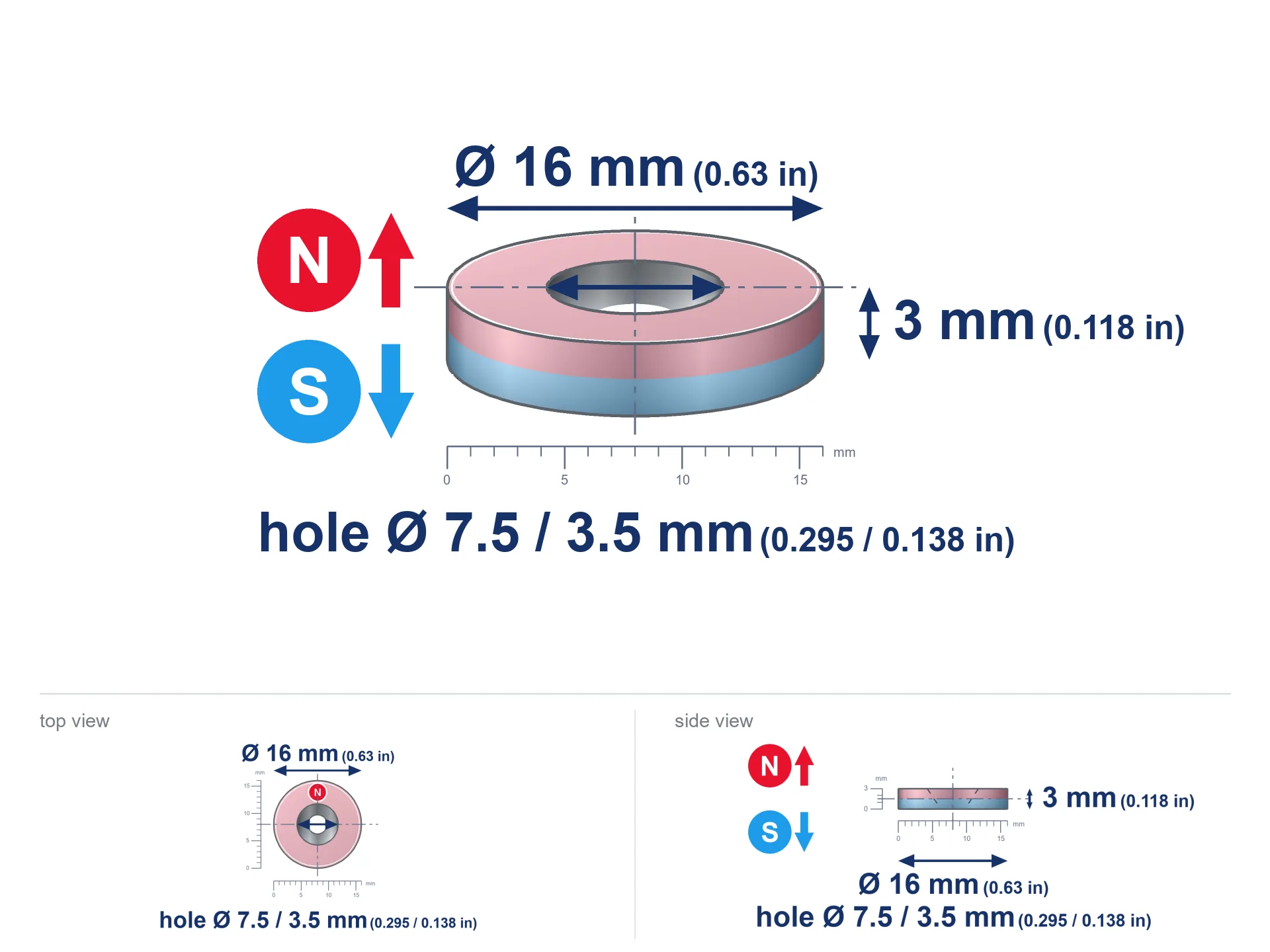
MP 16x7.5/3.5x3 / N38 - ring magnet
ring magnet
Catalog no 030567
- Diameter
- 16 mm [±0,1 mm]
- internal diameter Ø
- 7.5/3.5 mm [±0,1 mm]
- Height
- 3 mm [±0,1 mm]
How we measure these parameters — certificates and measurements
2.00 zł net / pcs
2.46 zł with VAT (23% VAT) / pcs
bulk discounts:
Need more?Frequently asked questions
Where can I compare prices of ring magnets for mounting in Poland?
Are ring magnets resistant to damage?
Which ring magnet is suitable for an outdoor structure?
Where can I check the available sizes of neodymium ring magnets?
Engineering report for this magnet
Full PDF analysis: pull and shear force, effect of distance, temperature and plate thickness, safety distances and the demagnetization curve.
Call us now
+48 888 99 98 98
alternatively let us know using
contact form
the contact section.
Specifications and structure of a neodymium magnet can be estimated using our
power calculator.
Order by 14:00 and we’ll ship today!
Technical data of the product - MP 16x7.5/3.5x3 / N38 - ring magnet
Specification / characteristics - MP 16x7.5/3.5x3 / N38 - ring magnet
| properties | values |
|---|---|
| Cat. no. | 030567 |
| Distributor | Dhit sp. z o.o. |
| Country of origin | Poland / China / Germany |
| Customs code | 85059029 |
| Diameter | 16 mm [±0,1 mm] |
| internal diameter Ø | 7.5/3.5 mm [±0,1 mm] |
| Height | 3 mm [±0,1 mm] |
| Magnetic Induction ~ ? | 0.00 mT / 0 Gs |
| Manufacturing Tolerance | ±0.1 mm |
Magnetic properties of material N38
| properties | values | units |
|---|---|---|
| Remanence Br ? | 12.2-12.6 | kGs |
| Remanence Br ? | 1220-1260 | mT |
| Coercivity bHc ? | 10.8-11.5 | kOe |
| Coercivity bHc ? | 860-915 | kA/m |
| Intrinsic coercivity iHc | ≥ 12 | kOe |
| Intrinsic coercivity iHc | ≥ 955 | kA/m |
| Energy product BHmax ? | 36-38 | BH max MGOe |
| Energy product BHmax ? | 287-303 | BH max KJ/m |
| Maximum working temperature ? | ≤ 80 | °C |
Physical properties of sintered neodymium magnets Nd2Fe14B at 20°C
| properties | values | units |
|---|---|---|
| Vickers hardness | ≥550 | Hv |
| Density | ≥7.4 | g/cm3 |
| Curie Temperature TC | 310 | °C |
| Curie Temperature TF | 590 | °F |
| Specific resistance | 150 | μΩ⋅cm |
| Bending strength | 250 | MPa |
| Compressive strength | 1000~1100 | MPa |
| Thermal expansion parallel (∥) to orientation (M) | (3-4) x 10-6 | °C-1 |
| Thermal expansion perpendicular (⊥) to orientation (M) | -(1-3) x 10-6 | °C-1 |
| Young's modulus | 1.7 x 10⁴ | kg/mm² |
Physical modeling of the product - technical parameters
Presented data represent the direct effect of a engineering calculation. Values are based on models for the class Nd2Fe14B. Real-world parameters might slightly differ. Please consider these data as a preliminary roadmap during assembly planning.
Table 1: Static force (force vs distance) - power drop
MP 16x7.5/3.5x3 / N38
| Distance (mm) | Induction (Gauss) / mT | Pull Force (kg/lbs/g/N) | Risk Status |
|---|---|---|---|
| 0 mm |
1882 Gs
188.2 mT
|
1.26 kg / 2.78 pounds
1259.6 g / 12.4 N
|
low risk |
| 1 mm |
1746 Gs
174.6 mT
|
1.08 kg / 2.39 pounds
1084.0 g / 10.6 N
|
low risk |
| 2 mm |
1561 Gs
156.1 mT
|
0.87 kg / 1.91 pounds
867.2 g / 8.5 N
|
low risk |
| 3 mm |
1357 Gs
135.7 mT
|
0.66 kg / 1.44 pounds
655.1 g / 6.4 N
|
low risk |
| 5 mm |
969 Gs
96.9 mT
|
0.33 kg / 0.74 pounds
334.3 g / 3.3 N
|
low risk |
| 10 mm |
387 Gs
38.7 mT
|
0.05 kg / 0.12 pounds
53.2 g / 0.5 N
|
low risk |
| 15 mm |
171 Gs
17.1 mT
|
0.01 kg / 0.02 pounds
10.4 g / 0.1 N
|
low risk |
| 20 mm |
87 Gs
8.7 mT
|
0.00 kg / 0.01 pounds
2.7 g / 0.0 N
|
low risk |
| 30 mm |
30 Gs
3.0 mT
|
0.00 kg / 0.00 pounds
0.3 g / 0.0 N
|
low risk |
| 50 mm |
7 Gs
0.7 mT
|
0.00 kg / 0.00 pounds
0.0 g / 0.0 N
|
low risk |
Table 2: Vertical force (wall)
MP 16x7.5/3.5x3 / N38
| Distance (mm) | Friction coefficient | Pull Force (kg/lbs/g/N) |
|---|---|---|
| 0 mm | Raw steel (µ ≈ 0.2) |
0.25 kg / 0.56 pounds
252.0 g / 2.5 N
|
| 1 mm | Raw steel (µ ≈ 0.2) |
0.22 kg / 0.48 pounds
216.0 g / 2.1 N
|
| 2 mm | Raw steel (µ ≈ 0.2) |
0.17 kg / 0.38 pounds
174.0 g / 1.7 N
|
| 3 mm | Raw steel (µ ≈ 0.2) |
0.13 kg / 0.29 pounds
132.0 g / 1.3 N
|
| 5 mm | Raw steel (µ ≈ 0.2) |
0.07 kg / 0.15 pounds
66.0 g / 0.6 N
|
| 10 mm | Raw steel (µ ≈ 0.2) |
0.01 kg / 0.02 pounds
10.0 g / 0.1 N
|
| 15 mm | Raw steel (µ ≈ 0.2) |
0.00 kg / 0.00 pounds
2.0 g / 0.0 N
|
| 20 mm | Raw steel (µ ≈ 0.2) |
0.00 kg / 0.00 pounds
0.0 g / 0.0 N
|
| 30 mm | Raw steel (µ ≈ 0.2) |
0.00 kg / 0.00 pounds
0.0 g / 0.0 N
|
| 50 mm | Raw steel (µ ≈ 0.2) |
0.00 kg / 0.00 pounds
0.0 g / 0.0 N
|
Table 3: Vertical assembly (shearing) - behavior on slippery surfaces
MP 16x7.5/3.5x3 / N38
| Surface type | Friction coefficient / % | Max load (kg/lbs/g/N) |
|---|---|---|
| Raw steel |
µ = 0.3
30% of nominal force
|
0.38 kg / 0.83 pounds
377.9 g / 3.7 N
|
| Painted steel (standard) |
µ = 0.2
20% of nominal force
|
0.25 kg / 0.56 pounds
251.9 g / 2.5 N
|
| Oily/slippery steel |
µ = 0.1
10% of nominal force
|
0.13 kg / 0.28 pounds
126.0 g / 1.2 N
|
| Magnet with anti-slip rubber |
µ = 0.5
50% of nominal force
|
0.63 kg / 1.39 pounds
629.8 g / 6.2 N
|
Table 4: Steel thickness (substrate influence) - sheet metal selection
MP 16x7.5/3.5x3 / N38
| Steel thickness (mm) | % power | Real pull force (kg/lbs/g/N) |
|---|---|---|
| 0.5 mm |
|
0.13 kg / 0.28 pounds
126.0 g / 1.2 N
|
| 1 mm |
|
0.31 kg / 0.69 pounds
314.9 g / 3.1 N
|
| 2 mm |
|
0.63 kg / 1.39 pounds
629.8 g / 6.2 N
|
| 3 mm |
|
0.94 kg / 2.08 pounds
944.7 g / 9.3 N
|
| 5 mm |
|
1.26 kg / 2.78 pounds
1259.6 g / 12.4 N
|
| 10 mm |
|
1.26 kg / 2.78 pounds
1259.6 g / 12.4 N
|
| 11 mm |
|
1.26 kg / 2.78 pounds
1259.6 g / 12.4 N
|
| 12 mm |
|
1.26 kg / 2.78 pounds
1259.6 g / 12.4 N
|
Table 5: Working in heat (material behavior) - resistance threshold
MP 16x7.5/3.5x3 / N38
| Magnet temperature (°C) | Force change relative to 20°C | Remaining pull (kg/lbs/g/N) | Status |
|---|---|---|---|
| 20 °C | 0.0% |
1.26 kg / 2.78 pounds
1259.6 g / 12.4 N
|
Estimate |
| 40 °C | -4.4% |
1.20 kg / 2.66 pounds
1204.8 g / 11.8 N
|
Estimate |
| 60 °C | -8.6% |
1.15 kg / 2.54 pounds
1151.2 g / 11.3 N
|
Estimate |
| 80 °C | -12.8% |
1.10 kg / 2.42 pounds
1098.9 g / 10.8 N
|
Material limit |
| 100 °C | — | — | Out of range — no model |
Table 6: Two magnets (attraction) - field range
MP 16x7.5/3.5x3 / N38
| Gap (mm) | Attraction (kg/lbs) (N-S) | Lateral Force (kg/lbs/g/N) | Repulsion (kg/lbs) (N-N) |
|---|---|---|---|
| 0 mm |
3.55 kg / 7.83 pounds
3 330 Gs
|
0.53 kg / 1.17 pounds
533 g / 5.2 N
|
N/A |
| 1 mm |
3.33 kg / 7.34 pounds
3 644 Gs
|
0.50 kg / 1.10 pounds
500 g / 4.9 N
|
3.00 kg / 6.61 pounds
~0 Gs
|
| 2 mm |
3.06 kg / 6.74 pounds
3 492 Gs
|
0.46 kg / 1.01 pounds
459 g / 4.5 N
|
2.75 kg / 6.07 pounds
~0 Gs
|
| 3 mm |
2.76 kg / 6.08 pounds
3 316 Gs
|
0.41 kg / 0.91 pounds
414 g / 4.1 N
|
2.48 kg / 5.47 pounds
~0 Gs
|
| 5 mm |
2.14 kg / 4.72 pounds
2 920 Gs
|
0.32 kg / 0.71 pounds
321 g / 3.1 N
|
1.93 kg / 4.24 pounds
~0 Gs
|
| 10 mm |
0.94 kg / 2.08 pounds
1 939 Gs
|
0.14 kg / 0.31 pounds
141 g / 1.4 N
|
0.85 kg / 1.87 pounds
~0 Gs
|
| 20 mm |
0.15 kg / 0.33 pounds
773 Gs
|
0.02 kg / 0.05 pounds
23 g / 0.2 N
|
0.14 kg / 0.30 pounds
~0 Gs
|
| 50 mm |
0.00 kg / 0.01 pounds
98 Gs
|
0.00 kg / 0.00 pounds
0 g / 0.0 N
|
0.00 kg / 0.00 pounds
~0 Gs
|
| 60 mm |
0.00 kg / 0.00 pounds
60 Gs
|
0.00 kg / 0.00 pounds
0 g / 0.0 N
|
0.00 kg / 0.00 pounds
~0 Gs
|
| 70 mm |
0.00 kg / 0.00 pounds
40 Gs
|
0.00 kg / 0.00 pounds
0 g / 0.0 N
|
0.00 kg / 0.00 pounds
~0 Gs
|
| 80 mm |
0.00 kg / 0.00 pounds
27 Gs
|
0.00 kg / 0.00 pounds
0 g / 0.0 N
|
0.00 kg / 0.00 pounds
~0 Gs
|
| 90 mm |
0.00 kg / 0.00 pounds
20 Gs
|
0.00 kg / 0.00 pounds
0 g / 0.0 N
|
0.00 kg / 0.00 pounds
~0 Gs
|
| 100 mm |
0.00 kg / 0.00 pounds
14 Gs
|
0.00 kg / 0.00 pounds
0 g / 0.0 N
|
0.00 kg / 0.00 pounds
~0 Gs
|
Table 7: Axial field levels — not safety zones
MP 16x7.5/3.5x3 / N38
| Field level (Gs) | mT | Model distance (cm) |
|---|---|---|
| < 5 Gs | < 0.5 mT | 6.0 cm |
| < 10 Gs | < 1.0 mT | 4.5 cm |
| < 20 Gs | < 2.0 mT | 3.5 cm |
| < 40 Gs | < 4.0 mT | 3.0 cm |
| < 50 Gs | < 5.0 mT | 2.5 cm |
| < 400 Gs | < 40.0 mT | 1.0 cm |
| < 600 Gs | < 60.0 mT | 1.0 cm |
Table 8: Impact energy (cracking risk) - warning
MP 16x7.5/3.5x3 / N38
| Start from (mm) | Speed (km/h) | Energy (J) | Predicted outcome |
|---|---|---|---|
| 10 mm |
17.95 km/h
(4.99 m/s)
|
0.05 J | |
| 30 mm |
18.27 km/h
(5.08 m/s)
|
0.05 J | |
| 50 mm |
18.27 km/h
(5.08 m/s)
|
0.05 J | |
| 100 mm |
18.27 km/h
(5.08 m/s)
|
0.05 J |
Table 9: Anti-corrosion coating durability
MP 16x7.5/3.5x3 / N38
| Technical parameter | Value / Description |
|---|---|
| Coating type | [NiCuNi] Nickel |
| Layer structure | Nickel - Copper - Nickel |
| Layer thickness | 10-20 µm |
| Salt spray test (SST) ? | 24 h |
| Recommended environment | Indoors only (dry) |
Table 10: Electrical data (Flux)
MP 16x7.5/3.5x3 / N38
| Parameter | Value | SI Unit / Description |
|---|---|---|
| Magnetic Flux | 3 780 Mx | 37.8 µWb |
| Pc Coefficient | 0.24 | Low (Flat) |
Table 11: Physics of underwater searching
MP 16x7.5/3.5x3 / N38
| Environment | Effective steel pull | Effect |
|---|---|---|
| Air (land) | 1.26 kg | Standard |
| Water (riverbed) |
1.44 kg
(+0.18 kg buoyancy gain)
|
+14.5% |
1. Wall mount (shear)
*Note: On a vertical surface, the magnet retains only ~20% of its perpendicular strength.
2. Plate thickness effect
*Thin metal sheet (e.g. computer case) drastically weakens the holding force.
3. Power loss vs temp
N38: the maximum material working temperature is 80°C. Permitted conditions also depend on the shape and magnetic circuit.
4. Demagnetization curve and operating point (B-H)
chart generated for the permeance coefficient Pc (Permeance Coefficient) = 0.24
The chart above illustrates the magnetic characteristics of the material within the second quadrant of the hysteresis loop. The solid red line represents the demagnetization curve (material potential), while the dashed blue line is the load line based on the magnet's geometry. The Pc (Permeance Coefficient), also known as the load line slope, is a dimensionless value that describes the relationship between the magnet's shape and its magnetic stability. The intersection of these two lines (the black dot) is the operating point — it determines the actual magnetic flux density generated by the magnet in this specific configuration. A higher Pc value means the magnet is more 'slender' (tall relative to its area), resulting in a higher operating point and better resistance to irreversible demagnetization caused by external fields or temperature. A value of 0.42 is relatively low (typical for flat magnets), meaning the operating point is closer to the 'knee' of the curve — caution is advised when operating at temperatures near the maximum limit to avoid strength loss.
Elemental analysis
| iron (Fe) | 64% – 68% |
| neodymium (Nd) | 29% – 32% |
| boron (B) | 1.1% – 1.2% |
| dysprosium (Dy) | 0.5% – 2.0% |
| coating (Ni-Cu-Ni) | < 0.05% |
Ecology and recycling (GPSR)
| recyclability (EoL) | 100% |
| recycled raw materials | ~10% (pre-cons) |
| carbon footprint | low / zredukowany |
| waste code (EWC) | 16 02 16 |
Other deals

Pros and cons of Nd2Fe14B magnets.
Advantages
- They have constant strength, and over nearly ten years their performance decreases symbolically – ~1% (in testing),
- Neodymium magnets are exceptionally resistant to demagnetization caused by magnetic disturbances,
- A magnet with a shiny nickel surface is more attractive,
- They are known for high magnetic induction at the operating surface, which affects their effectiveness,
- Made from properly selected components, these magnets show impressive resistance to high heat, enabling them to function (depending on their shape) at temperatures up to 230°C and above...
- Possibility of detailed creating and adjusting to precise requirements,
- Significant place in modern technologies – they serve a role in mass storage devices, electromotive mechanisms, diagnostic systems, as well as modern systems.
- Compactness – despite small sizes they provide effective action, making them ideal for precision applications
Limitations
- They are fragile upon too strong impacts. To avoid cracks, it is worth securing magnets using a steel holder. Such protection not only shields the magnet but also increases its resistance to damage
- Do not exceed this material temperature limit: 80°C. Overheating may permanently weaken the magnet.
- When exposed to humidity, magnets usually rust. To use them in conditions outside, it is recommended to use protective magnets, such as those in rubber or plastics, which prevent oxidation and corrosion.
- Due to limitations in realizing nuts and complex forms in magnets, we propose using a housing - magnetic mount.
- Potential hazard related to microscopic parts of magnets pose a threat, in case of ingestion, which gains importance in the aspect of protecting the youngest. Additionally, small elements of these magnets are able to be problematic in diagnostics medical after entering the body.
- Due to neodymium price, their price exceeds standard values,
Lifting parameters
Magnetic strength at its maximum – what contributes to it?
- with the application of a yoke made of special test steel, ensuring maximum field concentration
- with a thickness of at least 10 mm
- with an ideally smooth contact surface
- under conditions of gap-free contact (metal-to-metal)
- during pulling in a direction vertical to the plane
- at temperature approx. 20 degrees Celsius
Determinants of practical lifting force of a magnet
- Gap (between the magnet and the plate), because even a very small distance (e.g. 0.5 mm) results in a drastic drop in lifting capacity by up to 50% (this also applies to paint, corrosion or dirt).
- Direction of force – highest force is obtained only during perpendicular pulling. The resistance to sliding of the magnet along the plate is usually many times smaller (approx. 1/5 of the lifting capacity).
- Wall thickness – thin material does not allow full use of the magnet. Magnetic flux passes through the material instead of converting into lifting capacity.
- Steel grade – the best choice is high-permeability steel. Cast iron may generate lower lifting capacity.
- Surface finish – ideal contact is possible only on polished steel. Any scratches and bumps reduce the real contact area, reducing force.
- Operating temperature – neodymium magnets have a negative temperature coefficient. When it is hot they lose power, and at low temperatures gain strength (up to a certain limit).
Holding force was measured on a smooth steel plate of 20 mm thickness, when a perpendicular force was applied, however under attempts to slide the magnet the holding force is lower. In addition, even a slight gap between the magnet and the plate reduces the holding force.
H&S for magnets
Keep away from electronics
Navigation devices and mobile phones are highly sensitive to magnetic fields. Close proximity with a strong magnet can ruin the sensors in your phone.
Protective goggles
Despite the nickel coating, neodymium is delicate and cannot withstand shocks. Avoid impacts, as the magnet may crumble into sharp, dangerous pieces.
Danger to pacemakers
Individuals with a pacemaker should maintain an absolute distance from magnets. The magnetic field can disrupt the functioning of the implant.
Bone fractures
Large magnets can crush fingers instantly. Under no circumstances put your hand between two attracting surfaces.
Keep away from computers
Equipment safety: Strong magnets can damage data carriers and delicate electronics (heart implants, hearing aids, timepieces).
Do not give to children
NdFeB magnets are not suitable for play. Accidental ingestion of multiple magnets may result in them connecting inside the digestive tract, which poses a critical condition and requires immediate surgery.
Dust is flammable
Powder produced during cutting of magnets is combustible. Do not drill into magnets without proper cooling and knowledge.
Caution required
Before use, read the rules. Sudden snapping can destroy the magnet or hurt your hand. Be predictive.
Allergic reactions
Some people suffer from a sensitization to nickel, which is the common plating for neodymium magnets. Prolonged contact might lead to skin redness. We strongly advise use safety gloves.
Heat sensitivity
Do not exceed the maximum operating temperature stated in the specifications of the particular product. The limit depends on the material, geometry and operating arrangement; there is no single threshold for all neodymium magnets. Overheating can permanently weaken a magnet.
Tabela kosztu i czasu dostawy
Płatność przed wysyłką:

GLS kurier
Przesyłka będzie u Ciebie za 2-3 dni
14.99 ZŁ

InPost Paczkomaty 24/7
Przesyłka będzie u Ciebie za 1-2 dni
12.30 ZŁ
Płatność przy odbiorze (pobranie):
GLS kurier
Przesyłka będzie u Ciebie za 1-2 dni
23.00 ZŁ