


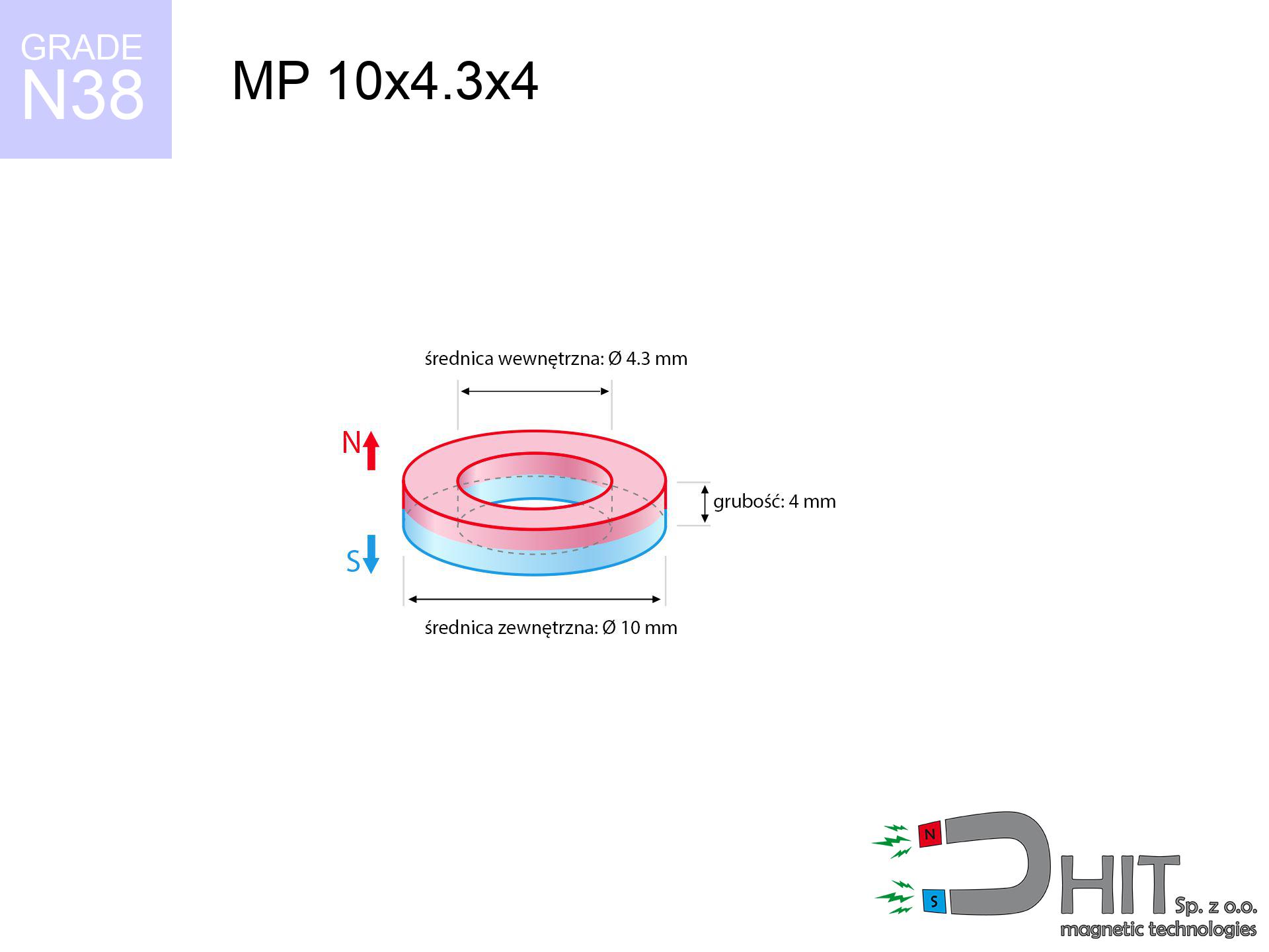
MP 10x4.3x4 / N38 - ring magnet
ring magnet
Catalog no 030178
GTIN/EAN: 5906301811954
- Diameter
- 10 mm [±0,1 mm]
- internal diameter Ø
- 4.3 mm [±0,1 mm]
- Height
- 4 mm [±0,1 mm]
- Weight
- 1.92 g
- Magnetization Direction
- ↑ axial
- Coating
- [NiCuNi] Nickel
How we measure these parameters — certificates and measurements
0.850 zł net / pcs
1.045 zł with VAT (23% VAT) / pcs
bulk discounts:
Need more?Frequently asked questions
Where can I compare prices of ring magnets for mounting in Poland?
Are ring magnets resistant to damage?
Which ring magnet is suitable for an outdoor structure?
Where can I check the available sizes of neodymium ring magnets?
Engineering report for this magnet
Full PDF analysis: pull and shear force, effect of distance, temperature and plate thickness, safety distances and the demagnetization curve.
Call us now
+48 888 99 98 98
alternatively let us know using
contact form
the contact section.
Specifications and structure of a neodymium magnet can be estimated using our
power calculator.
Order by 14:00 and we’ll ship today!
Technical of the product - MP 10x4.3x4 / N38 - ring magnet
Specification / characteristics - MP 10x4.3x4 / N38 - ring magnet
| properties | values |
|---|---|
| Cat. no. | 030178 |
| GTIN/EAN | 5906301811954 |
| Production/Distribution | Dhit sp. z o.o. |
| Country of origin | Poland / China / Germany |
| Customs code | 85059029 |
| Diameter | 10 mm [±0,1 mm] |
| internal diameter Ø | 4.3 mm [±0,1 mm] |
| Height | 4 mm [±0,1 mm] |
| Weight | 1.92 g |
| Magnetization Direction | ↑ axial |
| Load capacity ~ ? | 2.28 kg / 22.35 N |
| Magnetic Induction ~ ? | 386.91 mT / 3869 Gs |
| Coating | [NiCuNi] Nickel |
| Manufacturing Tolerance | ±0.1 mm |
Magnetic properties of material N38
| properties | values | units |
|---|---|---|
| Remanence Br ? | 12.2-12.6 | kGs |
| Remanence Br ? | 1220-1260 | mT |
| Coercivity bHc ? | 10.8-11.5 | kOe |
| Coercivity bHc ? | 860-915 | kA/m |
| Intrinsic coercivity iHc | ≥ 12 | kOe |
| Intrinsic coercivity iHc | ≥ 955 | kA/m |
| Energy product BHmax ? | 36-38 | BH max MGOe |
| Energy product BHmax ? | 287-303 | BH max KJ/m |
| Maximum working temperature ? | ≤ 80 | °C |
Physical properties of sintered neodymium magnets Nd2Fe14B at 20°C
| properties | values | units |
|---|---|---|
| Vickers hardness | ≥550 | Hv |
| Density | ≥7.4 | g/cm3 |
| Curie Temperature TC | 310 | °C |
| Curie Temperature TF | 590 | °F |
| Specific resistance | 150 | μΩ⋅cm |
| Bending strength | 250 | MPa |
| Compressive strength | 1000~1100 | MPa |
| Thermal expansion parallel (∥) to orientation (M) | (3-4) x 10-6 | °C-1 |
| Thermal expansion perpendicular (⊥) to orientation (M) | -(1-3) x 10-6 | °C-1 |
| Young's modulus | 1.7 x 10⁴ | kg/mm² |
Engineering modeling of the assembly - report
Presented data are the direct effect of a physical simulation. Results rely on algorithms for the material Nd2Fe14B. Operational performance may deviate from the simulation results. Please consider these calculations as a supplementary guide during assembly planning.
Table 1: Static force (force vs gap) - interaction chart
MP 10x4.3x4 / N38
| Distance (mm) | Induction (Gauss) / mT | Pull Force (kg/lbs/g/N) | Risk Status |
|---|---|---|---|
| 0 mm |
6115 Gs
611.5 mT
|
2.28 kg / 5.03 lbs
2280.0 g / 22.4 N
|
medium risk |
| 1 mm |
4915 Gs
491.5 mT
|
1.47 kg / 3.25 lbs
1473.3 g / 14.5 N
|
low risk |
| 2 mm |
3833 Gs
383.3 mT
|
0.90 kg / 1.97 lbs
895.7 g / 8.8 N
|
low risk |
| 3 mm |
2949 Gs
294.9 mT
|
0.53 kg / 1.17 lbs
530.3 g / 5.2 N
|
low risk |
| 5 mm |
1761 Gs
176.1 mT
|
0.19 kg / 0.42 lbs
189.1 g / 1.9 N
|
low risk |
| 10 mm |
612 Gs
61.2 mT
|
0.02 kg / 0.05 lbs
22.8 g / 0.2 N
|
low risk |
| 15 mm |
284 Gs
28.4 mT
|
0.00 kg / 0.01 lbs
4.9 g / 0.0 N
|
low risk |
| 20 mm |
157 Gs
15.7 mT
|
0.00 kg / 0.00 lbs
1.5 g / 0.0 N
|
low risk |
| 30 mm |
64 Gs
6.4 mT
|
0.00 kg / 0.00 lbs
0.3 g / 0.0 N
|
low risk |
| 50 mm |
19 Gs
1.9 mT
|
0.00 kg / 0.00 lbs
0.0 g / 0.0 N
|
low risk |
Table 2: Vertical capacity (vertical surface)
MP 10x4.3x4 / N38
| Distance (mm) | Friction coefficient | Pull Force (kg/lbs/g/N) |
|---|---|---|
| 0 mm | Stal (~0.2) |
0.46 kg / 1.01 lbs
456.0 g / 4.5 N
|
| 1 mm | Stal (~0.2) |
0.29 kg / 0.65 lbs
294.0 g / 2.9 N
|
| 2 mm | Stal (~0.2) |
0.18 kg / 0.40 lbs
180.0 g / 1.8 N
|
| 3 mm | Stal (~0.2) |
0.11 kg / 0.23 lbs
106.0 g / 1.0 N
|
| 5 mm | Stal (~0.2) |
0.04 kg / 0.08 lbs
38.0 g / 0.4 N
|
| 10 mm | Stal (~0.2) |
0.00 kg / 0.01 lbs
4.0 g / 0.0 N
|
| 15 mm | Stal (~0.2) |
0.00 kg / 0.00 lbs
0.0 g / 0.0 N
|
| 20 mm | Stal (~0.2) |
0.00 kg / 0.00 lbs
0.0 g / 0.0 N
|
| 30 mm | Stal (~0.2) |
0.00 kg / 0.00 lbs
0.0 g / 0.0 N
|
| 50 mm | Stal (~0.2) |
0.00 kg / 0.00 lbs
0.0 g / 0.0 N
|
Table 3: Vertical assembly (sliding) - vertical pull
MP 10x4.3x4 / N38
| Surface type | Friction coefficient / % Mocy | Max load (kg/lbs/g/N) |
|---|---|---|
| Raw steel |
µ = 0.3
30% Nominalnej Siły
|
0.68 kg / 1.51 lbs
684.0 g / 6.7 N
|
| Painted steel (standard) |
µ = 0.2
20% Nominalnej Siły
|
0.46 kg / 1.01 lbs
456.0 g / 4.5 N
|
| Oily/slippery steel |
µ = 0.1
10% Nominalnej Siły
|
0.23 kg / 0.50 lbs
228.0 g / 2.2 N
|
| Magnet with anti-slip rubber |
µ = 0.5
50% Nominalnej Siły
|
1.14 kg / 2.51 lbs
1140.0 g / 11.2 N
|
Table 4: Material efficiency (substrate influence) - sheet metal selection
MP 10x4.3x4 / N38
| Steel thickness (mm) | % power | Real pull force (kg/lbs/g/N) |
|---|---|---|
| 0.5 mm |
|
0.23 kg / 0.50 lbs
228.0 g / 2.2 N
|
| 1 mm |
|
0.57 kg / 1.26 lbs
570.0 g / 5.6 N
|
| 2 mm |
|
1.14 kg / 2.51 lbs
1140.0 g / 11.2 N
|
| 3 mm |
|
1.71 kg / 3.77 lbs
1710.0 g / 16.8 N
|
| 5 mm |
|
2.28 kg / 5.03 lbs
2280.0 g / 22.4 N
|
| 10 mm |
|
2.28 kg / 5.03 lbs
2280.0 g / 22.4 N
|
| 11 mm |
|
2.28 kg / 5.03 lbs
2280.0 g / 22.4 N
|
| 12 mm |
|
2.28 kg / 5.03 lbs
2280.0 g / 22.4 N
|
Table 5: Working in heat (material behavior) - power drop
MP 10x4.3x4 / N38
| Ambient temp. (°C) | Power loss | Remaining pull (kg/lbs/g/N) | Status |
|---|---|---|---|
| 20 °C | 0.0% |
2.28 kg / 5.03 lbs
2280.0 g / 22.4 N
|
OK |
| 40 °C | -2.2% |
2.23 kg / 4.92 lbs
2229.8 g / 21.9 N
|
OK |
| 60 °C | -4.4% |
2.18 kg / 4.81 lbs
2179.7 g / 21.4 N
|
OK |
| 80 °C | -6.6% |
2.13 kg / 4.69 lbs
2129.5 g / 20.9 N
|
|
| 100 °C | -28.8% |
1.62 kg / 3.58 lbs
1623.4 g / 15.9 N
|
Table 6: Two magnets (repulsion) - field range
MP 10x4.3x4 / N38
| Gap (mm) | Attraction (kg/lbs) (N-S) | Shear Force (kg/lbs/g/N) | Repulsion (kg/lbs) (N-N) |
|---|---|---|---|
| 0 mm |
12.93 kg / 28.50 lbs
6 169 Gs
|
1.94 kg / 4.27 lbs
1939 g / 19.0 N
|
N/A |
| 1 mm |
10.50 kg / 23.16 lbs
11 025 Gs
|
1.58 kg / 3.47 lbs
1576 g / 15.5 N
|
9.45 kg / 20.84 lbs
~0 Gs
|
| 2 mm |
8.35 kg / 18.41 lbs
9 831 Gs
|
1.25 kg / 2.76 lbs
1253 g / 12.3 N
|
7.52 kg / 16.57 lbs
~0 Gs
|
| 3 mm |
6.55 kg / 14.43 lbs
8 703 Gs
|
0.98 kg / 2.17 lbs
982 g / 9.6 N
|
5.89 kg / 12.99 lbs
~0 Gs
|
| 5 mm |
3.91 kg / 8.63 lbs
6 729 Gs
|
0.59 kg / 1.29 lbs
587 g / 5.8 N
|
3.52 kg / 7.76 lbs
~0 Gs
|
| 10 mm |
1.07 kg / 2.36 lbs
3 522 Gs
|
0.16 kg / 0.35 lbs
161 g / 1.6 N
|
0.96 kg / 2.13 lbs
~0 Gs
|
| 20 mm |
0.13 kg / 0.29 lbs
1 223 Gs
|
0.02 kg / 0.04 lbs
19 g / 0.2 N
|
0.12 kg / 0.26 lbs
~0 Gs
|
| 50 mm |
0.00 kg / 0.01 lbs
194 Gs
|
0.00 kg / 0.00 lbs
0 g / 0.0 N
|
0.00 kg / 0.00 lbs
~0 Gs
|
| 60 mm |
0.00 kg / 0.00 lbs
129 Gs
|
0.00 kg / 0.00 lbs
0 g / 0.0 N
|
0.00 kg / 0.00 lbs
~0 Gs
|
| 70 mm |
0.00 kg / 0.00 lbs
91 Gs
|
0.00 kg / 0.00 lbs
0 g / 0.0 N
|
0.00 kg / 0.00 lbs
~0 Gs
|
| 80 mm |
0.00 kg / 0.00 lbs
66 Gs
|
0.00 kg / 0.00 lbs
0 g / 0.0 N
|
0.00 kg / 0.00 lbs
~0 Gs
|
| 90 mm |
0.00 kg / 0.00 lbs
50 Gs
|
0.00 kg / 0.00 lbs
0 g / 0.0 N
|
0.00 kg / 0.00 lbs
~0 Gs
|
| 100 mm |
0.00 kg / 0.00 lbs
39 Gs
|
0.00 kg / 0.00 lbs
0 g / 0.0 N
|
0.00 kg / 0.00 lbs
~0 Gs
|
Table 7: Safety (HSE) (electronics) - warnings
MP 10x4.3x4 / N38
| Object / Device | Limit (Gauss) / mT | Safe distance |
|---|---|---|
| Pacemaker | 5 Gs (0.5 mT) | 9.0 cm |
| Hearing aid | 10 Gs (1.0 mT) | 7.0 cm |
| Timepiece | 20 Gs (2.0 mT) | 5.0 cm |
| Mobile device | 40 Gs (4.0 mT) | 4.0 cm |
| Remote | 50 Gs (5.0 mT) | 3.5 cm |
| Payment card | 400 Gs (40.0 mT) | 1.5 cm |
| HDD hard drive | 600 Gs (60.0 mT) | 1.5 cm |
Table 8: Impact energy (cracking risk) - warning
MP 10x4.3x4 / N38
| Start from (mm) | Speed (km/h) | Energy (J) | Predicted outcome |
|---|---|---|---|
| 10 mm |
25.10 km/h
(6.97 m/s)
|
0.05 J | |
| 30 mm |
25.30 km/h
(7.03 m/s)
|
0.05 J | |
| 50 mm |
25.30 km/h
(7.03 m/s)
|
0.05 J | |
| 100 mm |
25.30 km/h
(7.03 m/s)
|
0.05 J |
Table 9: Surface protection spec
MP 10x4.3x4 / N38
| Technical parameter | Value / Description |
|---|---|
| Coating type | [NiCuNi] Nickel |
| Layer structure | Nickel - Copper - Nickel |
| Layer thickness | 10-20 µm |
| Salt spray test (SST) ? | 24 h |
| Recommended environment | Indoors only (dry) |
Table 10: Construction data (Pc)
MP 10x4.3x4 / N38
| Parameter | Value | SI Unit / Description |
|---|---|---|
| Magnetic Flux | 4 017 Mx | 40.2 µWb |
| Pc Coefficient | 1.44 | High (Stable) |
Table 11: Submerged application
MP 10x4.3x4 / N38
| Environment | Effective steel pull | Effect |
|---|---|---|
| Air (land) | 2.28 kg | Standard |
| Water (riverbed) |
2.61 kg
(+0.33 kg buoyancy gain)
|
+14.5% |
1. Vertical hold
*Warning: On a vertical surface, the magnet retains merely ~20% of its nominal pull.
2. Steel saturation
*Thin steel (e.g. 0.5mm PC case) significantly limits the holding force.
3. Thermal stability
N38: the maximum material working temperature is 80°C. Permitted conditions also depend on the shape and magnetic circuit.
4. Demagnetization curve and operating point (B-H)
chart generated for the permeance coefficient Pc (Permeance Coefficient) = 1.44
The chart above illustrates the magnetic characteristics of the material within the second quadrant of the hysteresis loop. The solid red line represents the demagnetization curve (material potential), while the dashed blue line is the load line based on the magnet's geometry. The Pc (Permeance Coefficient), also known as the load line slope, is a dimensionless value that describes the relationship between the magnet's shape and its magnetic stability. The intersection of these two lines (the black dot) is the operating point — it determines the actual magnetic flux density generated by the magnet in this specific configuration. A higher Pc value means the magnet is more 'slender' (tall relative to its area), resulting in a higher operating point and better resistance to irreversible demagnetization caused by external fields or temperature. A value of 0.42 is relatively low (typical for flat magnets), meaning the operating point is closer to the 'knee' of the curve — caution is advised when operating at temperatures near the maximum limit to avoid strength loss.
Material specification
| iron (Fe) | 64% – 68% |
| neodymium (Nd) | 29% – 32% |
| boron (B) | 1.1% – 1.2% |
| dysprosium (Dy) | 0.5% – 2.0% |
| coating (Ni-Cu-Ni) | < 0.05% |
Sustainability
| recyclability (EoL) | 100% |
| recycled raw materials | ~10% (pre-cons) |
| carbon footprint | low / zredukowany |
| waste code (EWC) | 16 02 16 |
Other deals


Pros and cons of neodymium magnets.
Advantages
- They have unchanged lifting capacity, and over around 10 years their performance decreases symbolically – ~1% (according to theory),
- Magnets very well resist against loss of magnetization caused by ambient magnetic noise,
- A magnet with a shiny silver surface has an effective appearance,
- The surface of neodymium magnets generates a intense magnetic field – this is a distinguishing feature,
- Due to their durability and thermal resistance, neodymium magnets can operate (depending on the form) even at high temperatures reaching 230°C or more...
- Possibility of exact machining as well as adapting to defined requirements,
- Significant place in advanced technology sectors – they are utilized in hard drives, drive modules, precision medical tools, also technologically advanced constructions.
- Thanks to concentrated force, small magnets offer high operating force, in miniature format,
Disadvantages
- Brittleness is one of their disadvantages. Upon intense impact they can fracture. We recommend keeping them in a strong case, which not only protects them against impacts but also increases their durability
- Do not exceed this material temperature limit: 80°C. Overheating may permanently weaken the magnet.
- Due to the susceptibility of magnets to corrosion in a humid environment, we recommend using waterproof magnets made of rubber, plastic or other material resistant to moisture, in case of application outdoors
- We recommend a housing - magnetic mechanism, due to difficulties in creating nuts inside the magnet and complex forms.
- Health risk related to microscopic parts of magnets pose a threat, when accidentally swallowed, which is particularly important in the context of child safety. It is also worth noting that small elements of these devices can disrupt the diagnostic process medical when they are in the body.
- Higher cost of purchase is one of the disadvantages compared to ceramic magnets, especially in budget applications
Holding force characteristics
Maximum lifting capacity of the magnet – what contributes to it?
- using a sheet made of high-permeability steel, acting as a magnetic yoke
- with a cross-section no less than 10 mm
- with an ground touching surface
- under conditions of gap-free contact (metal-to-metal)
- during detachment in a direction perpendicular to the mounting surface
- at standard ambient temperature
Lifting capacity in real conditions – factors
- Gap (between the magnet and the metal), since even a tiny clearance (e.g. 0.5 mm) leads to a drastic drop in force by up to 50% (this also applies to varnish, rust or debris).
- Pull-off angle – note that the magnet has greatest strength perpendicularly. Under sliding down, the capacity drops significantly, often to levels of 20-30% of the nominal value.
- Substrate thickness – to utilize 100% power, the steel must be sufficiently thick. Paper-thin metal restricts the attraction force (the magnet "punches through" it).
- Material composition – different alloys attracts identically. High carbon content weaken the attraction effect.
- Smoothness – full contact is possible only on polished steel. Any scratches and bumps create air cushions, reducing force.
- Thermal factor – high temperature weakens magnetic field. Too high temperature can permanently damage the magnet.
Holding force was checked on the plate surface of 20 mm thickness, when a perpendicular force was applied, whereas under parallel forces the holding force is lower. In addition, even a small distance between the magnet and the plate lowers the load capacity.
Safe handling of NdFeB magnets
Maximum temperature
Watch the temperature. Heating the magnet above 80 degrees Celsius will destroy its properties and pulling force.
Bodily injuries
Mind your fingers. Two large magnets will snap together immediately with a force of massive weight, destroying everything in their path. Exercise extreme caution!
Implant safety
Individuals with a pacemaker should maintain an safe separation from magnets. The magnetism can stop the functioning of the life-saving device.
Cards and drives
Powerful magnetic fields can corrupt files on payment cards, HDDs, and storage devices. Keep a distance of min. 10 cm.
Precision electronics
A powerful magnetic field negatively affects the operation of compasses in smartphones and navigation systems. Maintain magnets close to a smartphone to avoid damaging the sensors.
Machining danger
Dust generated during machining of magnets is combustible. Do not drill into magnets without proper cooling and knowledge.
No play value
NdFeB magnets are not intended for children. Eating several magnets may result in them attracting across intestines, which poses a critical condition and requires immediate surgery.
Material brittleness
Protect your eyes. Magnets can fracture upon violent connection, launching shards into the air. Eye protection is mandatory.
Sensitization to coating
Warning for allergy sufferers: The nickel-copper-nickel coating consists of nickel. If redness appears, cease working with magnets and use protective gear.
Respect the power
Use magnets consciously. Their immense force can shock even professionals. Plan your moves and respect their force.
Tabela kosztu i czasu dostawy
Płatność przed wysyłką:

GLS kurier
Przesyłka będzie u Ciebie za 2-3 dni
14.99 ZŁ

InPost Paczkomaty 24/7
Przesyłka będzie u Ciebie za 1-2 dni
12.30 ZŁ
Płatność przy odbiorze (pobranie):
GLS kurier
Przesyłka będzie u Ciebie za 1-2 dni
23.00 ZŁ