
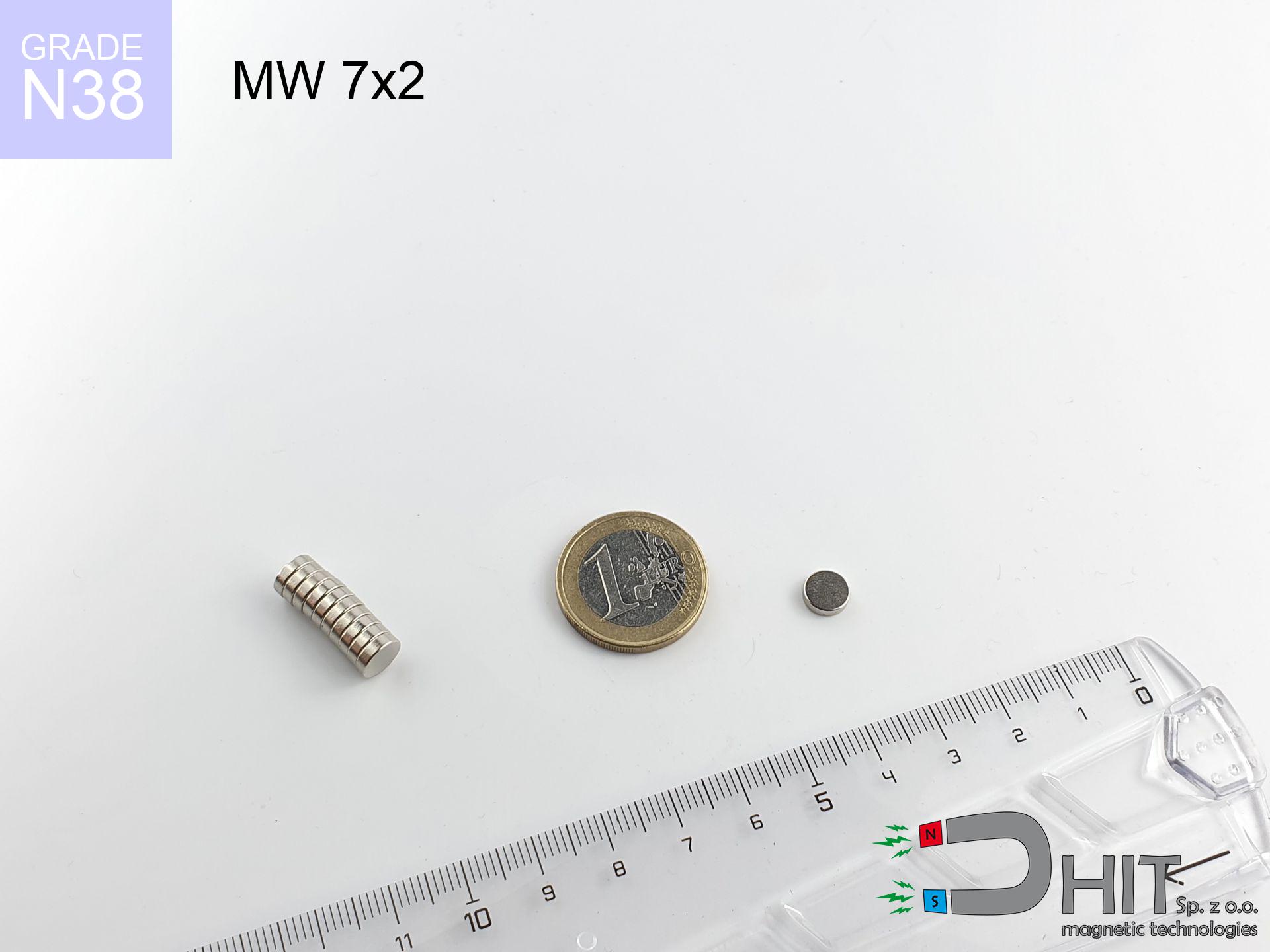
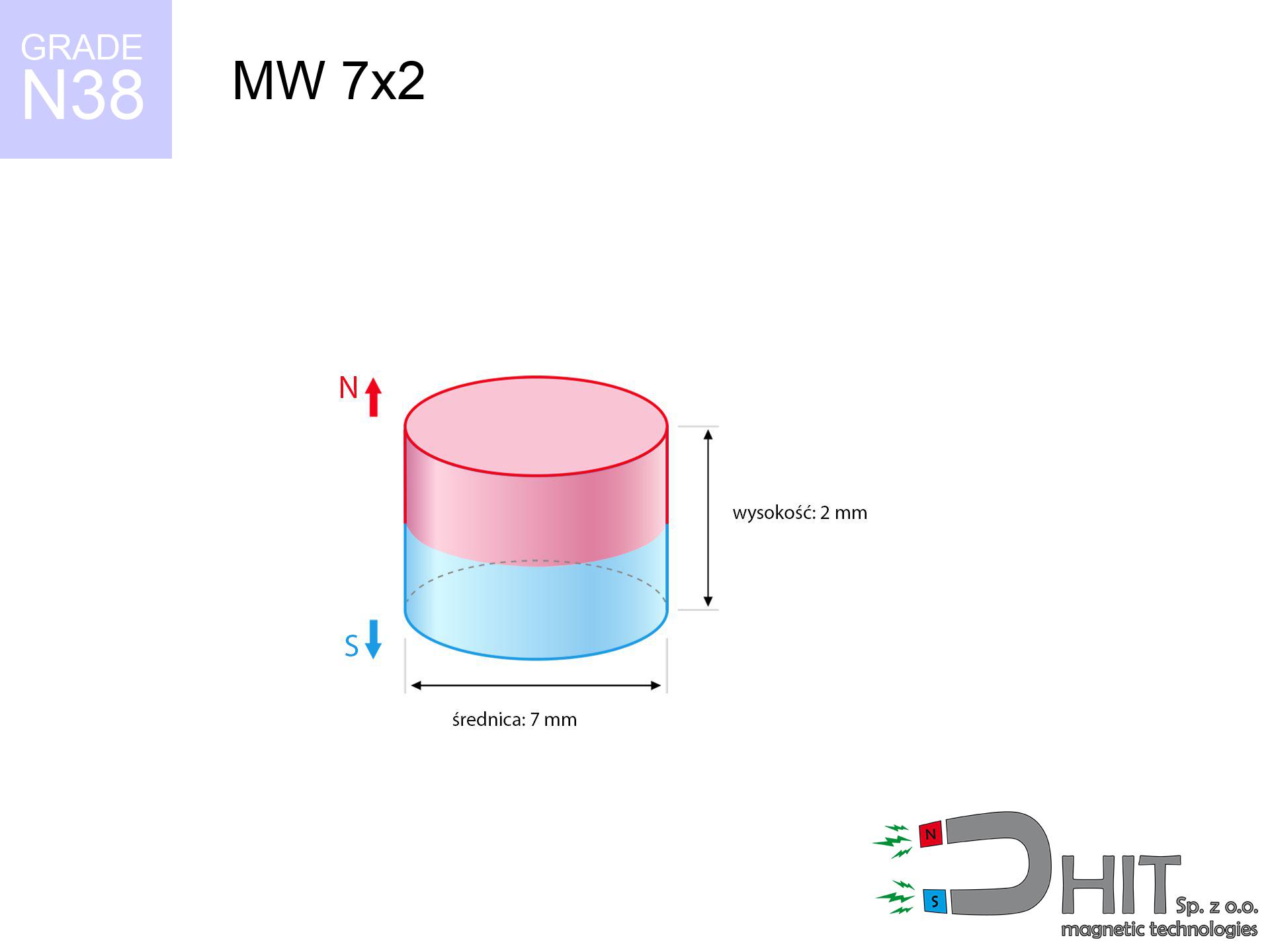
MW 7x2 / N38 - cylindrical magnet
cylindrical magnet
Catalog no 010099
GTIN/EAN: 5906301810988
Diameter Ø
7 mm [±0,1 mm]
Height
2 mm [±0,1 mm]
Weight
0.58 g
Magnetization Direction
↑ axial
Load capacity
0.99 kg / 9.76 N
Magnetic Induction
307.23 mT / 3072 Gs
Coating
[NiCuNi] Nickel
0.381 ZŁ with VAT / pcs + price for transport
0.310 ZŁ net + 23% VAT / pcs
bulk discounts:
Need more?
Pick up the phone and ask
+48 22 499 98 98
otherwise send us a note using
request form
the contact page.
Parameters as well as structure of magnetic components can be estimated using our
force calculator.
Same-day processing for orders placed before 14:00.
Product card - MW 7x2 / N38 - cylindrical magnet
Specification / characteristics - MW 7x2 / N38 - cylindrical magnet
| properties | values |
|---|---|
| Cat. no. | 010099 |
| GTIN/EAN | 5906301810988 |
| Production/Distribution | Dhit sp. z o.o. |
| Country of origin | Poland / China / Germany |
| Customs code | 85059029 |
| Diameter Ø | 7 mm [±0,1 mm] |
| Height | 2 mm [±0,1 mm] |
| Weight | 0.58 g |
| Magnetization Direction | ↑ axial |
| Load capacity ~ ? | 0.99 kg / 9.76 N |
| Magnetic Induction ~ ? | 307.23 mT / 3072 Gs |
| Coating | [NiCuNi] Nickel |
| Manufacturing Tolerance | ±0.1 mm |
Magnetic properties of material N38
| properties | values | units |
|---|---|---|
| remenance Br [min. - max.] ? | 12.2-12.6 | kGs |
| remenance Br [min. - max.] ? | 1220-1260 | mT |
| coercivity bHc ? | 10.8-11.5 | kOe |
| coercivity bHc ? | 860-915 | kA/m |
| actual internal force iHc | ≥ 12 | kOe |
| actual internal force iHc | ≥ 955 | kA/m |
| energy density [min. - max.] ? | 36-38 | BH max MGOe |
| energy density [min. - max.] ? | 287-303 | BH max KJ/m |
| max. temperature ? | ≤ 80 | °C |
Physical properties of sintered neodymium magnets Nd2Fe14B at 20°C
| properties | values | units |
|---|---|---|
| Vickers hardness | ≥550 | Hv |
| Density | ≥7.4 | g/cm3 |
| Curie Temperature TC | 312 - 380 | °C |
| Curie Temperature TF | 593 - 716 | °F |
| Specific resistance | 150 | μΩ⋅cm |
| Bending strength | 250 | MPa |
| Compressive strength | 1000~1100 | MPa |
| Thermal expansion parallel (∥) to orientation (M) | (3-4) x 10-6 | °C-1 |
| Thermal expansion perpendicular (⊥) to orientation (M) | -(1-3) x 10-6 | °C-1 |
| Young's modulus | 1.7 x 10⁴ | kg/mm² |
Engineering analysis of the product - report
These values are the direct effect of a engineering analysis. Values rely on models for the material Nd2Fe14B. Actual parameters might slightly differ. Use these calculations as a supplementary guide for designers.
Table 1: Static pull force (force vs gap) - power drop
MW 7x2 / N38
| Distance (mm) | Induction (Gauss) / mT | Pull Force (kg/lbs/g/N) | Risk Status |
|---|---|---|---|
| 0 mm |
3070 Gs
307.0 mT
|
0.99 kg / 2.18 pounds
990.0 g / 9.7 N
|
safe |
| 1 mm |
2332 Gs
233.2 mT
|
0.57 kg / 1.26 pounds
571.1 g / 5.6 N
|
safe |
| 2 mm |
1590 Gs
159.0 mT
|
0.27 kg / 0.59 pounds
265.5 g / 2.6 N
|
safe |
| 3 mm |
1044 Gs
104.4 mT
|
0.11 kg / 0.25 pounds
114.6 g / 1.1 N
|
safe |
| 5 mm |
466 Gs
46.6 mT
|
0.02 kg / 0.05 pounds
22.8 g / 0.2 N
|
safe |
| 10 mm |
100 Gs
10.0 mT
|
0.00 kg / 0.00 pounds
1.1 g / 0.0 N
|
safe |
| 15 mm |
35 Gs
3.5 mT
|
0.00 kg / 0.00 pounds
0.1 g / 0.0 N
|
safe |
| 20 mm |
16 Gs
1.6 mT
|
0.00 kg / 0.00 pounds
0.0 g / 0.0 N
|
safe |
| 30 mm |
5 Gs
0.5 mT
|
0.00 kg / 0.00 pounds
0.0 g / 0.0 N
|
safe |
| 50 mm |
1 Gs
0.1 mT
|
0.00 kg / 0.00 pounds
0.0 g / 0.0 N
|
safe |
Table 2: Sliding load (vertical surface)
MW 7x2 / N38
| Distance (mm) | Friction coefficient | Pull Force (kg/lbs/g/N) |
|---|---|---|
| 0 mm | Stal (~0.2) |
0.20 kg / 0.44 pounds
198.0 g / 1.9 N
|
| 1 mm | Stal (~0.2) |
0.11 kg / 0.25 pounds
114.0 g / 1.1 N
|
| 2 mm | Stal (~0.2) |
0.05 kg / 0.12 pounds
54.0 g / 0.5 N
|
| 3 mm | Stal (~0.2) |
0.02 kg / 0.05 pounds
22.0 g / 0.2 N
|
| 5 mm | Stal (~0.2) |
0.00 kg / 0.01 pounds
4.0 g / 0.0 N
|
| 10 mm | Stal (~0.2) |
0.00 kg / 0.00 pounds
0.0 g / 0.0 N
|
| 15 mm | Stal (~0.2) |
0.00 kg / 0.00 pounds
0.0 g / 0.0 N
|
| 20 mm | Stal (~0.2) |
0.00 kg / 0.00 pounds
0.0 g / 0.0 N
|
| 30 mm | Stal (~0.2) |
0.00 kg / 0.00 pounds
0.0 g / 0.0 N
|
| 50 mm | Stal (~0.2) |
0.00 kg / 0.00 pounds
0.0 g / 0.0 N
|
Table 3: Vertical assembly (sliding) - behavior on slippery surfaces
MW 7x2 / N38
| Surface type | Friction coefficient / % Mocy | Max load (kg/lbs/g/N) |
|---|---|---|
| Raw steel |
µ = 0.3
30% Nominalnej Siły
|
0.30 kg / 0.65 pounds
297.0 g / 2.9 N
|
| Painted steel (standard) |
µ = 0.2
20% Nominalnej Siły
|
0.20 kg / 0.44 pounds
198.0 g / 1.9 N
|
| Oily/slippery steel |
µ = 0.1
10% Nominalnej Siły
|
0.10 kg / 0.22 pounds
99.0 g / 1.0 N
|
| Magnet with anti-slip rubber |
µ = 0.5
50% Nominalnej Siły
|
0.50 kg / 1.09 pounds
495.0 g / 4.9 N
|
Table 4: Material efficiency (substrate influence) - power losses
MW 7x2 / N38
| Steel thickness (mm) | % power | Real pull force (kg/lbs/g/N) |
|---|---|---|
| 0.5 mm |
|
0.10 kg / 0.22 pounds
99.0 g / 1.0 N
|
| 1 mm |
|
0.25 kg / 0.55 pounds
247.5 g / 2.4 N
|
| 2 mm |
|
0.50 kg / 1.09 pounds
495.0 g / 4.9 N
|
| 3 mm |
|
0.74 kg / 1.64 pounds
742.5 g / 7.3 N
|
| 5 mm |
|
0.99 kg / 2.18 pounds
990.0 g / 9.7 N
|
| 10 mm |
|
0.99 kg / 2.18 pounds
990.0 g / 9.7 N
|
| 11 mm |
|
0.99 kg / 2.18 pounds
990.0 g / 9.7 N
|
| 12 mm |
|
0.99 kg / 2.18 pounds
990.0 g / 9.7 N
|
Table 5: Working in heat (material behavior) - power drop
MW 7x2 / N38
| Ambient temp. (°C) | Power loss | Remaining pull (kg/lbs/g/N) | Status |
|---|---|---|---|
| 20 °C | 0.0% |
0.99 kg / 2.18 pounds
990.0 g / 9.7 N
|
OK |
| 40 °C | -2.2% |
0.97 kg / 2.13 pounds
968.2 g / 9.5 N
|
OK |
| 60 °C | -4.4% |
0.95 kg / 2.09 pounds
946.4 g / 9.3 N
|
|
| 80 °C | -6.6% |
0.92 kg / 2.04 pounds
924.7 g / 9.1 N
|
|
| 100 °C | -28.8% |
0.70 kg / 1.55 pounds
704.9 g / 6.9 N
|
Table 6: Two magnets (attraction) - forces in the system
MW 7x2 / N38
| Gap (mm) | Attraction (kg/lbs) (N-S) | Lateral Force (kg/lbs/g/N) | Repulsion (kg/lbs) (N-N) |
|---|---|---|---|
| 0 mm |
2.24 kg / 4.93 pounds
4 653 Gs
|
0.34 kg / 0.74 pounds
335 g / 3.3 N
|
N/A |
| 1 mm |
1.76 kg / 3.89 pounds
5 454 Gs
|
0.26 kg / 0.58 pounds
265 g / 2.6 N
|
1.59 kg / 3.50 pounds
~0 Gs
|
| 2 mm |
1.29 kg / 2.84 pounds
4 663 Gs
|
0.19 kg / 0.43 pounds
193 g / 1.9 N
|
1.16 kg / 2.56 pounds
~0 Gs
|
| 3 mm |
0.89 kg / 1.97 pounds
3 884 Gs
|
0.13 kg / 0.30 pounds
134 g / 1.3 N
|
0.81 kg / 1.77 pounds
~0 Gs
|
| 5 mm |
0.40 kg / 0.87 pounds
2 581 Gs
|
0.06 kg / 0.13 pounds
59 g / 0.6 N
|
0.36 kg / 0.78 pounds
~0 Gs
|
| 10 mm |
0.05 kg / 0.11 pounds
932 Gs
|
0.01 kg / 0.02 pounds
8 g / 0.1 N
|
0.05 kg / 0.10 pounds
~0 Gs
|
| 20 mm |
0.00 kg / 0.01 pounds
200 Gs
|
0.00 kg / 0.00 pounds
0 g / 0.0 N
|
0.00 kg / 0.00 pounds
~0 Gs
|
| 50 mm |
0.00 kg / 0.00 pounds
17 Gs
|
0.00 kg / 0.00 pounds
0 g / 0.0 N
|
0.00 kg / 0.00 pounds
~0 Gs
|
| 60 mm |
0.00 kg / 0.00 pounds
10 Gs
|
0.00 kg / 0.00 pounds
0 g / 0.0 N
|
0.00 kg / 0.00 pounds
~0 Gs
|
| 70 mm |
0.00 kg / 0.00 pounds
6 Gs
|
0.00 kg / 0.00 pounds
0 g / 0.0 N
|
0.00 kg / 0.00 pounds
~0 Gs
|
| 80 mm |
0.00 kg / 0.00 pounds
4 Gs
|
0.00 kg / 0.00 pounds
0 g / 0.0 N
|
0.00 kg / 0.00 pounds
~0 Gs
|
| 90 mm |
0.00 kg / 0.00 pounds
3 Gs
|
0.00 kg / 0.00 pounds
0 g / 0.0 N
|
0.00 kg / 0.00 pounds
~0 Gs
|
| 100 mm |
0.00 kg / 0.00 pounds
2 Gs
|
0.00 kg / 0.00 pounds
0 g / 0.0 N
|
0.00 kg / 0.00 pounds
~0 Gs
|
Table 7: Protective zones (electronics) - precautionary measures
MW 7x2 / N38
| Object / Device | Limit (Gauss) / mT | Safe distance |
|---|---|---|
| Pacemaker | 5 Gs (0.5 mT) | 3.5 cm |
| Hearing aid | 10 Gs (1.0 mT) | 2.5 cm |
| Mechanical watch | 20 Gs (2.0 mT) | 2.0 cm |
| Mobile device | 40 Gs (4.0 mT) | 1.5 cm |
| Car key | 50 Gs (5.0 mT) | 1.5 cm |
| Payment card | 400 Gs (40.0 mT) | 1.0 cm |
| HDD hard drive | 600 Gs (60.0 mT) | 0.5 cm |
Table 8: Collisions (cracking risk) - warning
MW 7x2 / N38
| Start from (mm) | Speed (km/h) | Energy (J) | Predicted outcome |
|---|---|---|---|
| 10 mm |
41.69 km/h
(11.58 m/s)
|
0.04 J | |
| 30 mm |
72.17 km/h
(20.05 m/s)
|
0.12 J | |
| 50 mm |
93.17 km/h
(25.88 m/s)
|
0.19 J | |
| 100 mm |
131.76 km/h
(36.60 m/s)
|
0.39 J |
Table 9: Corrosion resistance
MW 7x2 / N38
| Technical parameter | Value / Description |
|---|---|
| Coating type | [NiCuNi] Nickel |
| Layer structure | Nickel - Copper - Nickel |
| Layer thickness | 10-20 µm |
| Salt spray test (SST) ? | 24 h |
| Recommended environment | Indoors only (dry) |
Table 10: Electrical data (Flux)
MW 7x2 / N38
| Parameter | Value | SI Unit / Description |
|---|---|---|
| Magnetic Flux | 1 284 Mx | 12.8 µWb |
| Pc Coefficient | 0.39 | Low (Flat) |
Table 11: Underwater work (magnet fishing)
MW 7x2 / N38
| Environment | Effective steel pull | Effect |
|---|---|---|
| Air (land) | 0.99 kg | Standard |
| Water (riverbed) |
1.13 kg
(+0.14 kg buoyancy gain)
|
+14.5% |
1. Shear force
*Note: On a vertical surface, the magnet holds only a fraction of its nominal pull.
2. Steel thickness impact
*Thin metal sheet (e.g. computer case) severely reduces the holding force.
3. Heat tolerance
*For standard magnets, the max working temp is 80°C.
4. Demagnetization curve and operating point (B-H)
chart generated for the permeance coefficient Pc (Permeance Coefficient) = 0.39
This simulation demonstrates the magnetic stability of the selected magnet under specific geometric conditions. The solid red line represents the demagnetization curve (material potential), while the dashed blue line is the load line based on the magnet's geometry. The Pc (Permeance Coefficient), also known as the load line slope, is a dimensionless value that describes the relationship between the magnet's shape and its magnetic stability. The intersection of these two lines (the black dot) is the operating point — it determines the actual magnetic flux density generated by the magnet in this specific configuration. A higher Pc value means the magnet is more 'slender' (tall relative to its area), resulting in a higher operating point and better resistance to irreversible demagnetization caused by external fields or temperature. A value of 0.42 is relatively low (typical for flat magnets), meaning the operating point is closer to the 'knee' of the curve — caution is advised when operating at temperatures near the maximum limit to avoid strength loss.
Elemental analysis
| iron (Fe) | 64% – 68% |
| neodymium (Nd) | 29% – 32% |
| boron (B) | 1.1% – 1.2% |
| dysprosium (Dy) | 0.5% – 2.0% |
| coating (Ni-Cu-Ni) | < 0.05% |
Sustainability
| recyclability (EoL) | 100% |
| recycled raw materials | ~10% (pre-cons) |
| carbon footprint | low / zredukowany |
| waste code (EWC) | 16 02 16 |
View more products

![UMH 36x8x46 [M6] / N38 - magnetic holder with hook](https://cdn3.dhit.pl/graphics/products/umh-36x8x46-m6-wim.jpg "UMH 36x8x46 [M6] / N38 - magnetic holder with hook")


Pros as well as cons of neodymium magnets.
Benefits
- They have unchanged lifting capacity, and over around ten years their performance decreases symbolically – ~1% (in testing),
- Magnets effectively defend themselves against demagnetization caused by ambient magnetic noise,
- The use of an shiny layer of noble metals (nickel, gold, silver) causes the element to have aesthetics,
- Magnets have exceptionally strong magnetic induction on the outer layer,
- Through (appropriate) combination of ingredients, they can achieve high thermal resistance, allowing for action at temperatures reaching 230°C and above...
- Thanks to modularity in constructing and the ability to adapt to specific needs,
- Versatile presence in modern technologies – they are used in data components, brushless drives, diagnostic systems, also other advanced devices.
- Compactness – despite small sizes they provide effective action, making them ideal for precision applications
Weaknesses
- They are fragile upon heavy impacts. To avoid cracks, it is worth securing magnets in special housings. Such protection not only protects the magnet but also increases its resistance to damage
- Neodymium magnets decrease their force under the influence of heating. As soon as 80°C is exceeded, many of them start losing their force. Therefore, we recommend our special magnets marked [AH], which maintain stability even at temperatures up to 230°C
- Due to the susceptibility of magnets to corrosion in a humid environment, we advise using waterproof magnets made of rubber, plastic or other material stable to moisture, in case of application outdoors
- We suggest cover - magnetic mount, due to difficulties in realizing nuts inside the magnet and complex forms.
- Potential hazard to health – tiny shards of magnets are risky, in case of ingestion, which is particularly important in the aspect of protecting the youngest. Furthermore, tiny parts of these magnets are able to disrupt the diagnostic process medical when they are in the body.
- With mass production the cost of neodymium magnets is economically unviable,
Pull force analysis
Highest magnetic holding force – what it depends on?
- with the application of a sheet made of low-carbon steel, guaranteeing full magnetic saturation
- whose transverse dimension reaches at least 10 mm
- characterized by lack of roughness
- without any air gap between the magnet and steel
- during pulling in a direction vertical to the mounting surface
- in neutral thermal conditions
Lifting capacity in practice – influencing factors
- Distance – existence of foreign body (rust, tape, gap) interrupts the magnetic circuit, which reduces capacity rapidly (even by 50% at 0.5 mm).
- Pull-off angle – remember that the magnet holds strongest perpendicularly. Under sliding down, the capacity drops drastically, often to levels of 20-30% of the maximum value.
- Steel thickness – insufficiently thick plate causes magnetic saturation, causing part of the flux to be escaped into the air.
- Material type – the best choice is high-permeability steel. Stainless steels may have worse magnetic properties.
- Surface condition – ground elements ensure maximum contact, which increases force. Rough surfaces weaken the grip.
- Temperature – heating the magnet results in weakening of induction. Check the thermal limit for a given model.
Lifting capacity testing was carried out on plates with a smooth surface of suitable thickness, under perpendicular forces, whereas under parallel forces the lifting capacity is smaller. Moreover, even a slight gap between the magnet and the plate lowers the load capacity.
H&S for magnets
Health Danger
Individuals with a ICD have to maintain an large gap from magnets. The magnetic field can disrupt the functioning of the implant.
Choking Hazard
NdFeB magnets are not toys. Accidental ingestion of a few magnets may result in them connecting inside the digestive tract, which constitutes a severe health hazard and necessitates urgent medical intervention.
Avoid contact if allergic
Certain individuals experience a sensitization to nickel, which is the common plating for neodymium magnets. Prolonged contact might lead to a rash. We suggest use protective gloves.
Serious injuries
Watch your fingers. Two powerful magnets will snap together instantly with a force of massive weight, destroying anything in their path. Be careful!
Machining danger
Fire warning: Neodymium dust is explosive. Avoid machining magnets in home conditions as this risks ignition.
Protect data
Device Safety: Strong magnets can damage payment cards and sensitive devices (heart implants, hearing aids, mechanical watches).
Risk of cracking
NdFeB magnets are sintered ceramics, meaning they are very brittle. Impact of two magnets leads to them cracking into shards.
GPS Danger
Be aware: neodymium magnets generate a field that disrupts precision electronics. Keep a safe distance from your mobile, device, and navigation systems.
Power loss in heat
Monitor thermal conditions. Heating the magnet above 80 degrees Celsius will permanently weaken its properties and strength.
Caution required
Before use, check safety instructions. Uncontrolled attraction can break the magnet or hurt your hand. Be predictive.
Tabela kosztu i czasu dostawy
Płatność przed wysyłką:

GLS kurier
Przesyłka będzie u Ciebie za 2-3 dni
14.99 ZŁ

InPost Paczkomaty 24/7
Przesyłka będzie u Ciebie za 1-2 dni
12.30 ZŁ
Płatność przy odbiorze (pobranie):
GLS kurier
Przesyłka będzie u Ciebie za 1-2 dni
23.00 ZŁ
Rate the product
Your rating