
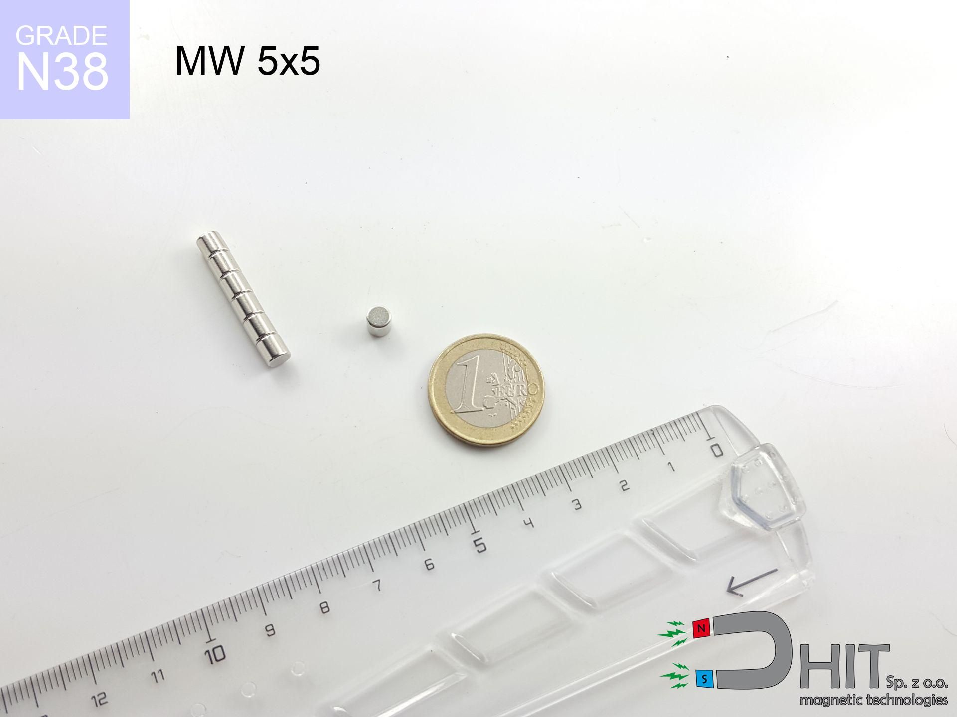
MW 5x5 / N38 - cylindrical magnet
cylindrical magnet
Catalog no 010503
GTIN/EAN: 5906301814979
Diameter Ø
5 mm [±0,1 mm]
Height
5 mm [±0,1 mm]
Weight
0.74 g
Magnetization Direction
↑ axial
Load capacity
0.79 kg / 7.76 N
Magnetic Induction
553.14 mT / 5531 Gs
Coating
[NiCuNi] Nickel
0.394 ZŁ with VAT / pcs + price for transport
0.320 ZŁ net + 23% VAT / pcs
bulk discounts:
Need more?
Pick up the phone and ask
+48 888 99 98 98
or send us a note through
our online form
through our site.
Weight along with form of a magnet can be verified with our
force calculator.
Orders placed before 14:00 will be shipped the same business day.
Technical - MW 5x5 / N38 - cylindrical magnet
Specification / characteristics - MW 5x5 / N38 - cylindrical magnet
| properties | values |
|---|---|
| Cat. no. | 010503 |
| GTIN/EAN | 5906301814979 |
| Production/Distribution | Dhit sp. z o.o. |
| Country of origin | Poland / China / Germany |
| Customs code | 85059029 |
| Diameter Ø | 5 mm [±0,1 mm] |
| Height | 5 mm [±0,1 mm] |
| Weight | 0.74 g |
| Magnetization Direction | ↑ axial |
| Load capacity ~ ? | 0.79 kg / 7.76 N |
| Magnetic Induction ~ ? | 553.14 mT / 5531 Gs |
| Coating | [NiCuNi] Nickel |
| Manufacturing Tolerance | ±0.1 mm |
Magnetic properties of material N38
| properties | values | units |
|---|---|---|
| remenance Br [min. - max.] ? | 12.2-12.6 | kGs |
| remenance Br [min. - max.] ? | 1220-1260 | mT |
| coercivity bHc ? | 10.8-11.5 | kOe |
| coercivity bHc ? | 860-915 | kA/m |
| actual internal force iHc | ≥ 12 | kOe |
| actual internal force iHc | ≥ 955 | kA/m |
| energy density [min. - max.] ? | 36-38 | BH max MGOe |
| energy density [min. - max.] ? | 287-303 | BH max KJ/m |
| max. temperature ? | ≤ 80 | °C |
Physical properties of sintered neodymium magnets Nd2Fe14B at 20°C
| properties | values | units |
|---|---|---|
| Vickers hardness | ≥550 | Hv |
| Density | ≥7.4 | g/cm3 |
| Curie Temperature TC | 312 - 380 | °C |
| Curie Temperature TF | 593 - 716 | °F |
| Specific resistance | 150 | μΩ⋅cm |
| Bending strength | 250 | MPa |
| Compressive strength | 1000~1100 | MPa |
| Thermal expansion parallel (∥) to orientation (M) | (3-4) x 10-6 | °C-1 |
| Thermal expansion perpendicular (⊥) to orientation (M) | -(1-3) x 10-6 | °C-1 |
| Young's modulus | 1.7 x 10⁴ | kg/mm² |
Technical simulation of the product - technical parameters
These data constitute the direct effect of a mathematical calculation. Results are based on models for the material Nd2Fe14B. Real-world performance may differ from theoretical values. Treat these calculations as a supplementary guide when designing systems.
Table 1: Static force (pull vs distance) - power drop
MW 5x5 / N38
| Distance (mm) | Induction (Gauss) / mT | Pull Force (kg/lbs/g/N) | Risk Status |
|---|---|---|---|
| 0 mm |
5523 Gs
552.3 mT
|
0.79 kg / 1.74 lbs
790.0 g / 7.7 N
|
weak grip |
| 1 mm |
3420 Gs
342.0 mT
|
0.30 kg / 0.67 lbs
303.0 g / 3.0 N
|
weak grip |
| 2 mm |
1966 Gs
196.6 mT
|
0.10 kg / 0.22 lbs
100.1 g / 1.0 N
|
weak grip |
| 3 mm |
1155 Gs
115.5 mT
|
0.03 kg / 0.08 lbs
34.5 g / 0.3 N
|
weak grip |
| 5 mm |
469 Gs
46.9 mT
|
0.01 kg / 0.01 lbs
5.7 g / 0.1 N
|
weak grip |
| 10 mm |
101 Gs
10.1 mT
|
0.00 kg / 0.00 lbs
0.3 g / 0.0 N
|
weak grip |
| 15 mm |
36 Gs
3.6 mT
|
0.00 kg / 0.00 lbs
0.0 g / 0.0 N
|
weak grip |
| 20 mm |
17 Gs
1.7 mT
|
0.00 kg / 0.00 lbs
0.0 g / 0.0 N
|
weak grip |
| 30 mm |
6 Gs
0.6 mT
|
0.00 kg / 0.00 lbs
0.0 g / 0.0 N
|
weak grip |
| 50 mm |
1 Gs
0.1 mT
|
0.00 kg / 0.00 lbs
0.0 g / 0.0 N
|
weak grip |
Table 2: Shear hold (wall)
MW 5x5 / N38
| Distance (mm) | Friction coefficient | Pull Force (kg/lbs/g/N) |
|---|---|---|
| 0 mm | Stal (~0.2) |
0.16 kg / 0.35 lbs
158.0 g / 1.5 N
|
| 1 mm | Stal (~0.2) |
0.06 kg / 0.13 lbs
60.0 g / 0.6 N
|
| 2 mm | Stal (~0.2) |
0.02 kg / 0.04 lbs
20.0 g / 0.2 N
|
| 3 mm | Stal (~0.2) |
0.01 kg / 0.01 lbs
6.0 g / 0.1 N
|
| 5 mm | Stal (~0.2) |
0.00 kg / 0.00 lbs
2.0 g / 0.0 N
|
| 10 mm | Stal (~0.2) |
0.00 kg / 0.00 lbs
0.0 g / 0.0 N
|
| 15 mm | Stal (~0.2) |
0.00 kg / 0.00 lbs
0.0 g / 0.0 N
|
| 20 mm | Stal (~0.2) |
0.00 kg / 0.00 lbs
0.0 g / 0.0 N
|
| 30 mm | Stal (~0.2) |
0.00 kg / 0.00 lbs
0.0 g / 0.0 N
|
| 50 mm | Stal (~0.2) |
0.00 kg / 0.00 lbs
0.0 g / 0.0 N
|
Table 3: Vertical assembly (sliding) - behavior on slippery surfaces
MW 5x5 / N38
| Surface type | Friction coefficient / % Mocy | Max load (kg/lbs/g/N) |
|---|---|---|
| Raw steel |
µ = 0.3
30% Nominalnej Siły
|
0.24 kg / 0.52 lbs
237.0 g / 2.3 N
|
| Painted steel (standard) |
µ = 0.2
20% Nominalnej Siły
|
0.16 kg / 0.35 lbs
158.0 g / 1.5 N
|
| Oily/slippery steel |
µ = 0.1
10% Nominalnej Siły
|
0.08 kg / 0.17 lbs
79.0 g / 0.8 N
|
| Magnet with anti-slip rubber |
µ = 0.5
50% Nominalnej Siły
|
0.40 kg / 0.87 lbs
395.0 g / 3.9 N
|
Table 4: Steel thickness (saturation) - power losses
MW 5x5 / N38
| Steel thickness (mm) | % power | Real pull force (kg/lbs/g/N) |
|---|---|---|
| 0.5 mm |
|
0.08 kg / 0.17 lbs
79.0 g / 0.8 N
|
| 1 mm |
|
0.20 kg / 0.44 lbs
197.5 g / 1.9 N
|
| 2 mm |
|
0.40 kg / 0.87 lbs
395.0 g / 3.9 N
|
| 3 mm |
|
0.59 kg / 1.31 lbs
592.5 g / 5.8 N
|
| 5 mm |
|
0.79 kg / 1.74 lbs
790.0 g / 7.7 N
|
| 10 mm |
|
0.79 kg / 1.74 lbs
790.0 g / 7.7 N
|
| 11 mm |
|
0.79 kg / 1.74 lbs
790.0 g / 7.7 N
|
| 12 mm |
|
0.79 kg / 1.74 lbs
790.0 g / 7.7 N
|
Table 5: Thermal stability (material behavior) - resistance threshold
MW 5x5 / N38
| Ambient temp. (°C) | Power loss | Remaining pull (kg/lbs/g/N) | Status |
|---|---|---|---|
| 20 °C | 0.0% |
0.79 kg / 1.74 lbs
790.0 g / 7.7 N
|
OK |
| 40 °C | -2.2% |
0.77 kg / 1.70 lbs
772.6 g / 7.6 N
|
OK |
| 60 °C | -4.4% |
0.76 kg / 1.67 lbs
755.2 g / 7.4 N
|
OK |
| 80 °C | -6.6% |
0.74 kg / 1.63 lbs
737.9 g / 7.2 N
|
|
| 100 °C | -28.8% |
0.56 kg / 1.24 lbs
562.5 g / 5.5 N
|
Table 6: Magnet-Magnet interaction (attraction) - forces in the system
MW 5x5 / N38
| Gap (mm) | Attraction (kg/lbs) (N-S) | Shear Strength (kg/lbs/g/N) | Repulsion (kg/lbs) (N-N) |
|---|---|---|---|
| 0 mm |
3.69 kg / 8.14 lbs
5 990 Gs
|
0.55 kg / 1.22 lbs
554 g / 5.4 N
|
N/A |
| 1 mm |
2.37 kg / 5.23 lbs
8 857 Gs
|
0.36 kg / 0.79 lbs
356 g / 3.5 N
|
2.14 kg / 4.71 lbs
~0 Gs
|
| 2 mm |
1.42 kg / 3.12 lbs
6 841 Gs
|
0.21 kg / 0.47 lbs
212 g / 2.1 N
|
1.27 kg / 2.81 lbs
~0 Gs
|
| 3 mm |
0.82 kg / 1.80 lbs
5 194 Gs
|
0.12 kg / 0.27 lbs
122 g / 1.2 N
|
0.73 kg / 1.62 lbs
~0 Gs
|
| 5 mm |
0.27 kg / 0.60 lbs
2 996 Gs
|
0.04 kg / 0.09 lbs
41 g / 0.4 N
|
0.24 kg / 0.54 lbs
~0 Gs
|
| 10 mm |
0.03 kg / 0.06 lbs
939 Gs
|
0.00 kg / 0.01 lbs
4 g / 0.0 N
|
0.02 kg / 0.05 lbs
~0 Gs
|
| 20 mm |
0.00 kg / 0.00 lbs
202 Gs
|
0.00 kg / 0.00 lbs
0 g / 0.0 N
|
0.00 kg / 0.00 lbs
~0 Gs
|
| 50 mm |
0.00 kg / 0.00 lbs
19 Gs
|
0.00 kg / 0.00 lbs
0 g / 0.0 N
|
0.00 kg / 0.00 lbs
~0 Gs
|
| 60 mm |
0.00 kg / 0.00 lbs
11 Gs
|
0.00 kg / 0.00 lbs
0 g / 0.0 N
|
0.00 kg / 0.00 lbs
~0 Gs
|
| 70 mm |
0.00 kg / 0.00 lbs
7 Gs
|
0.00 kg / 0.00 lbs
0 g / 0.0 N
|
0.00 kg / 0.00 lbs
~0 Gs
|
| 80 mm |
0.00 kg / 0.00 lbs
5 Gs
|
0.00 kg / 0.00 lbs
0 g / 0.0 N
|
0.00 kg / 0.00 lbs
~0 Gs
|
| 90 mm |
0.00 kg / 0.00 lbs
4 Gs
|
0.00 kg / 0.00 lbs
0 g / 0.0 N
|
0.00 kg / 0.00 lbs
~0 Gs
|
| 100 mm |
0.00 kg / 0.00 lbs
3 Gs
|
0.00 kg / 0.00 lbs
0 g / 0.0 N
|
0.00 kg / 0.00 lbs
~0 Gs
|
Table 7: Safety (HSE) (implants) - warnings
MW 5x5 / N38
| Object / Device | Limit (Gauss) / mT | Safe distance |
|---|---|---|
| Pacemaker | 5 Gs (0.5 mT) | 3.5 cm |
| Hearing aid | 10 Gs (1.0 mT) | 2.5 cm |
| Timepiece | 20 Gs (2.0 mT) | 2.0 cm |
| Mobile device | 40 Gs (4.0 mT) | 1.5 cm |
| Car key | 50 Gs (5.0 mT) | 1.5 cm |
| Payment card | 400 Gs (40.0 mT) | 1.0 cm |
| HDD hard drive | 600 Gs (60.0 mT) | 0.5 cm |
Table 8: Collisions (kinetic energy) - warning
MW 5x5 / N38
| Start from (mm) | Speed (km/h) | Energy (J) | Predicted outcome |
|---|---|---|---|
| 10 mm |
32.96 km/h
(9.16 m/s)
|
0.03 J | |
| 30 mm |
57.07 km/h
(15.85 m/s)
|
0.09 J | |
| 50 mm |
73.68 km/h
(20.47 m/s)
|
0.15 J | |
| 100 mm |
104.20 km/h
(28.95 m/s)
|
0.31 J |
Table 9: Corrosion resistance
MW 5x5 / N38
| Technical parameter | Value / Description |
|---|---|
| Coating type | [NiCuNi] Nickel |
| Layer structure | Nickel - Copper - Nickel |
| Layer thickness | 10-20 µm |
| Salt spray test (SST) ? | 24 h |
| Recommended environment | Indoors only (dry) |
Table 10: Construction data (Flux)
MW 5x5 / N38
| Parameter | Value | SI Unit / Description |
|---|---|---|
| Magnetic Flux | 1 120 Mx | 11.2 µWb |
| Pc Coefficient | 0.89 | High (Stable) |
Table 11: Hydrostatics and buoyancy
MW 5x5 / N38
| Environment | Effective steel pull | Effect |
|---|---|---|
| Air (land) | 0.79 kg | Standard |
| Water (riverbed) |
0.90 kg
(+0.11 kg buoyancy gain)
|
+14.5% |
1. Sliding resistance
*Caution: On a vertical wall, the magnet holds just a fraction of its nominal pull.
2. Steel thickness impact
*Thin steel (e.g. computer case) severely limits the holding force.
3. Heat tolerance
*For N38 material, the critical limit is 80°C.
4. Demagnetization curve and operating point (B-H)
chart generated for the permeance coefficient Pc (Permeance Coefficient) = 0.89
The chart above illustrates the magnetic characteristics of the material within the second quadrant of the hysteresis loop. The solid red line represents the demagnetization curve (material potential), while the dashed blue line is the load line based on the magnet's geometry. The Pc (Permeance Coefficient), also known as the load line slope, is a dimensionless value that describes the relationship between the magnet's shape and its magnetic stability. The intersection of these two lines (the black dot) is the operating point — it determines the actual magnetic flux density generated by the magnet in this specific configuration. A higher Pc value means the magnet is more 'slender' (tall relative to its area), resulting in a higher operating point and better resistance to irreversible demagnetization caused by external fields or temperature. A value of 0.42 is relatively low (typical for flat magnets), meaning the operating point is closer to the 'knee' of the curve — caution is advised when operating at temperatures near the maximum limit to avoid strength loss.
Elemental analysis
| iron (Fe) | 64% – 68% |
| neodymium (Nd) | 29% – 32% |
| boron (B) | 1.1% – 1.2% |
| dysprosium (Dy) | 0.5% – 2.0% |
| coating (Ni-Cu-Ni) | < 0.05% |
Ecology and recycling (GPSR)
| recyclability (EoL) | 100% |
| recycled raw materials | ~10% (pre-cons) |
| carbon footprint | low / zredukowany |
| waste code (EWC) | 16 02 16 |
View also proposals

![UI 39x9x7 [BA] - badge holder](https://cdn3.dhit.pl/graphics/products/ui39x9x7-dav.jpg "UI 39x9x7 [BA] - badge holder")


Pros and cons of neodymium magnets.
Benefits
- They have constant strength, and over nearly 10 years their performance decreases symbolically – ~1% (according to theory),
- They retain their magnetic properties even under close interference source,
- The use of an metallic finish of noble metals (nickel, gold, silver) causes the element to present itself better,
- They feature high magnetic induction at the operating surface, which affects their effectiveness,
- Made from properly selected components, these magnets show impressive resistance to high heat, enabling them to function (depending on their shape) at temperatures up to 230°C and above...
- Possibility of precise creating as well as adjusting to specific needs,
- Significant place in electronics industry – they serve a role in hard drives, electric motors, precision medical tools, as well as industrial machines.
- Relatively small size with high pulling force – neodymium magnets offer high power in compact dimensions, which enables their usage in small systems
Disadvantages
- To avoid cracks upon strong impacts, we recommend using special steel housings. Such a solution secures the magnet and simultaneously increases its durability.
- We warn that neodymium magnets can reduce their power at high temperatures. To prevent this, we suggest our specialized [AH] magnets, which work effectively even at 230°C.
- Due to the susceptibility of magnets to corrosion in a humid environment, we recommend using waterproof magnets made of rubber, plastic or other material stable to moisture, in case of application outdoors
- Due to limitations in creating nuts and complicated shapes in magnets, we recommend using a housing - magnetic mechanism.
- Potential hazard to health – tiny shards of magnets pose a threat, if swallowed, which gains importance in the aspect of protecting the youngest. Additionally, small components of these devices are able to disrupt the diagnostic process medical after entering the body.
- With large orders the cost of neodymium magnets can be a barrier,
Holding force characteristics
Detachment force of the magnet in optimal conditions – what contributes to it?
- with the contact of a sheet made of special test steel, guaranteeing maximum field concentration
- whose thickness equals approx. 10 mm
- with a surface free of scratches
- without the slightest clearance between the magnet and steel
- for force applied at a right angle (in the magnet axis)
- at ambient temperature approx. 20 degrees Celsius
Impact of factors on magnetic holding capacity in practice
- Air gap (between the magnet and the metal), since even a tiny clearance (e.g. 0.5 mm) leads to a decrease in lifting capacity by up to 50% (this also applies to varnish, rust or dirt).
- Load vector – maximum parameter is available only during perpendicular pulling. The force required to slide of the magnet along the plate is standardly many times smaller (approx. 1/5 of the lifting capacity).
- Substrate thickness – to utilize 100% power, the steel must be adequately massive. Paper-thin metal limits the attraction force (the magnet "punches through" it).
- Steel grade – ideal substrate is high-permeability steel. Stainless steels may attract less.
- Smoothness – ideal contact is possible only on smooth steel. Rough texture create air cushions, reducing force.
- Temperature – heating the magnet causes a temporary drop of induction. Check the thermal limit for a given model.
Lifting capacity was measured by applying a polished steel plate of optimal thickness (min. 20 mm), under perpendicular detachment force, however under attempts to slide the magnet the holding force is lower. Moreover, even a small distance between the magnet’s surface and the plate reduces the load capacity.
H&S for magnets
Electronic hazard
Very strong magnetic fields can destroy records on payment cards, HDDs, and storage devices. Stay away of at least 10 cm.
Respect the power
Exercise caution. Neodymium magnets act from a long distance and connect with massive power, often quicker than you can react.
Fire warning
Fire warning: Rare earth powder is highly flammable. Do not process magnets in home conditions as this may cause fire.
Precision electronics
Navigation devices and smartphones are highly sensitive to magnetism. Direct contact with a strong magnet can permanently damage the sensors in your phone.
Beware of splinters
Protect your eyes. Magnets can explode upon uncontrolled impact, launching sharp fragments into the air. Eye protection is mandatory.
No play value
These products are not intended for children. Eating a few magnets may result in them pinching intestinal walls, which constitutes a critical condition and necessitates urgent medical intervention.
Pacemakers
Health Alert: Neodymium magnets can deactivate pacemakers and defibrillators. Stay away if you have medical devices.
Operating temperature
Keep cool. NdFeB magnets are susceptible to heat. If you require operation above 80°C, ask us about HT versions (H, SH, UH).
Avoid contact if allergic
Some people have a sensitization to Ni, which is the common plating for neodymium magnets. Prolonged contact can result in skin redness. It is best to use safety gloves.
Crushing force
Mind your fingers. Two large magnets will join immediately with a force of several hundred kilograms, crushing everything in their path. Be careful!
Tabela kosztu i czasu dostawy
Płatność przed wysyłką:

GLS kurier
Przesyłka będzie u Ciebie za 2-3 dni
14.99 ZŁ

InPost Paczkomaty 24/7
Przesyłka będzie u Ciebie za 1-2 dni
12.30 ZŁ
Płatność przy odbiorze (pobranie):
GLS kurier
Przesyłka będzie u Ciebie za 1-2 dni
23.00 ZŁ
Rate the product
Your rating