
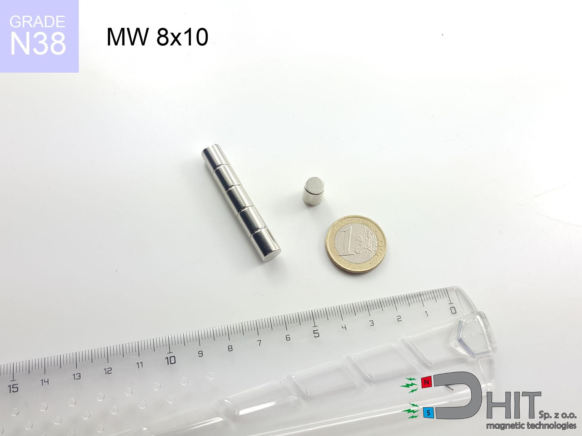
MW 8x10 / N38 - cylindrical magnet
cylindrical magnet
Catalog no 010504
GTIN/EAN: 5906301814993
Diameter Ø
8 mm [±0,1 mm]
Height
10 mm [±0,1 mm]
Weight
3.77 g
Magnetization Direction
↑ axial
Load capacity
1.84 kg / 18.00 N
Magnetic Induction
574.74 mT / 5747 Gs
Coating
[NiCuNi] Nickel
1.501 ZŁ with VAT / pcs + price for transport
1.220 ZŁ net + 23% VAT / pcs
bulk discounts:
Need more?Engineering report for this magnet
Full PDF analysis: pull and shear force, effect of distance, temperature and plate thickness, safety distances and the demagnetization curve.
Pick up the phone and ask
+48 888 99 98 98
or get in touch via
request form
through our site.
Lifting power and shape of a magnet can be tested on our
force calculator.
Same-day shipping for orders placed before 14:00.
Product card - MW 8x10 / N38 - cylindrical magnet
Specification / characteristics - MW 8x10 / N38 - cylindrical magnet
| properties | values |
|---|---|
| Cat. no. | 010504 |
| GTIN/EAN | 5906301814993 |
| Production/Distribution | Dhit sp. z o.o. |
| Country of origin | Poland / China / Germany |
| Customs code | 85059029 |
| Diameter Ø | 8 mm [±0,1 mm] |
| Height | 10 mm [±0,1 mm] |
| Weight | 3.77 g |
| Magnetization Direction | ↑ axial |
| Load capacity ~ ? | 1.84 kg / 18.00 N |
| Magnetic Induction ~ ? | 574.74 mT / 5747 Gs |
| Coating | [NiCuNi] Nickel |
| Manufacturing Tolerance | ±0.1 mm |
Magnetic properties of material N38
| properties | values | units |
|---|---|---|
| remenance Br [min. - max.] ? | 12.2-12.6 | kGs |
| remenance Br [min. - max.] ? | 1220-1260 | mT |
| coercivity bHc ? | 10.8-11.5 | kOe |
| coercivity bHc ? | 860-915 | kA/m |
| actual internal force iHc | ≥ 12 | kOe |
| actual internal force iHc | ≥ 955 | kA/m |
| energy density [min. - max.] ? | 36-38 | BH max MGOe |
| energy density [min. - max.] ? | 287-303 | BH max KJ/m |
| max. temperature ? | ≤ 80 | °C |
Physical properties of sintered neodymium magnets Nd2Fe14B at 20°C
| properties | values | units |
|---|---|---|
| Vickers hardness | ≥550 | Hv |
| Density | ≥7.4 | g/cm3 |
| Curie Temperature TC | 312 - 380 | °C |
| Curie Temperature TF | 593 - 716 | °F |
| Specific resistance | 150 | μΩ⋅cm |
| Bending strength | 250 | MPa |
| Compressive strength | 1000~1100 | MPa |
| Thermal expansion parallel (∥) to orientation (M) | (3-4) x 10-6 | °C-1 |
| Thermal expansion perpendicular (⊥) to orientation (M) | -(1-3) x 10-6 | °C-1 |
| Young's modulus | 1.7 x 10⁴ | kg/mm² |
Engineering simulation of the product - technical parameters
These data represent the direct effect of a engineering simulation. Values are based on models for the class Nd2Fe14B. Actual parameters may deviate from the simulation results. Use these calculations as a reference point for designers.
Table 1: Static pull force (force vs gap) - characteristics
MW 8x10 / N38
| Distance (mm) | Induction (Gauss) / mT | Pull Force (kg/lbs/g/N) | Risk Status |
|---|---|---|---|
| 0 mm |
5742 Gs
574.2 mT
|
1.84 kg / 4.06 pounds
1840.0 g / 18.1 N
|
weak grip |
| 1 mm |
4323 Gs
432.3 mT
|
1.04 kg / 2.30 pounds
1043.0 g / 10.2 N
|
weak grip |
| 2 mm |
3109 Gs
310.9 mT
|
0.54 kg / 1.19 pounds
539.5 g / 5.3 N
|
weak grip |
| 3 mm |
2206 Gs
220.6 mT
|
0.27 kg / 0.60 pounds
271.6 g / 2.7 N
|
weak grip |
| 5 mm |
1149 Gs
114.9 mT
|
0.07 kg / 0.16 pounds
73.7 g / 0.7 N
|
weak grip |
| 10 mm |
323 Gs
32.3 mT
|
0.01 kg / 0.01 pounds
5.8 g / 0.1 N
|
weak grip |
| 15 mm |
131 Gs
13.1 mT
|
0.00 kg / 0.00 pounds
1.0 g / 0.0 N
|
weak grip |
| 20 mm |
66 Gs
6.6 mT
|
0.00 kg / 0.00 pounds
0.2 g / 0.0 N
|
weak grip |
| 30 mm |
24 Gs
2.4 mT
|
0.00 kg / 0.00 pounds
0.0 g / 0.0 N
|
weak grip |
| 50 mm |
6 Gs
0.6 mT
|
0.00 kg / 0.00 pounds
0.0 g / 0.0 N
|
weak grip |
Table 2: Vertical load (wall)
MW 8x10 / N38
| Distance (mm) | Friction coefficient | Pull Force (kg/lbs/g/N) |
|---|---|---|
| 0 mm | Stal (~0.2) |
0.37 kg / 0.81 pounds
368.0 g / 3.6 N
|
| 1 mm | Stal (~0.2) |
0.21 kg / 0.46 pounds
208.0 g / 2.0 N
|
| 2 mm | Stal (~0.2) |
0.11 kg / 0.24 pounds
108.0 g / 1.1 N
|
| 3 mm | Stal (~0.2) |
0.05 kg / 0.12 pounds
54.0 g / 0.5 N
|
| 5 mm | Stal (~0.2) |
0.01 kg / 0.03 pounds
14.0 g / 0.1 N
|
| 10 mm | Stal (~0.2) |
0.00 kg / 0.00 pounds
2.0 g / 0.0 N
|
| 15 mm | Stal (~0.2) |
0.00 kg / 0.00 pounds
0.0 g / 0.0 N
|
| 20 mm | Stal (~0.2) |
0.00 kg / 0.00 pounds
0.0 g / 0.0 N
|
| 30 mm | Stal (~0.2) |
0.00 kg / 0.00 pounds
0.0 g / 0.0 N
|
| 50 mm | Stal (~0.2) |
0.00 kg / 0.00 pounds
0.0 g / 0.0 N
|
Table 3: Wall mounting (sliding) - behavior on slippery surfaces
MW 8x10 / N38
| Surface type | Friction coefficient / % Mocy | Max load (kg/lbs/g/N) |
|---|---|---|
| Raw steel |
µ = 0.3
30% Nominalnej Siły
|
0.55 kg / 1.22 pounds
552.0 g / 5.4 N
|
| Painted steel (standard) |
µ = 0.2
20% Nominalnej Siły
|
0.37 kg / 0.81 pounds
368.0 g / 3.6 N
|
| Oily/slippery steel |
µ = 0.1
10% Nominalnej Siły
|
0.18 kg / 0.41 pounds
184.0 g / 1.8 N
|
| Magnet with anti-slip rubber |
µ = 0.5
50% Nominalnej Siły
|
0.92 kg / 2.03 pounds
920.0 g / 9.0 N
|
Table 4: Steel thickness (substrate influence) - sheet metal selection
MW 8x10 / N38
| Steel thickness (mm) | % power | Real pull force (kg/lbs/g/N) |
|---|---|---|
| 0.5 mm |
|
0.18 kg / 0.41 pounds
184.0 g / 1.8 N
|
| 1 mm |
|
0.46 kg / 1.01 pounds
460.0 g / 4.5 N
|
| 2 mm |
|
0.92 kg / 2.03 pounds
920.0 g / 9.0 N
|
| 3 mm |
|
1.38 kg / 3.04 pounds
1380.0 g / 13.5 N
|
| 5 mm |
|
1.84 kg / 4.06 pounds
1840.0 g / 18.1 N
|
| 10 mm |
|
1.84 kg / 4.06 pounds
1840.0 g / 18.1 N
|
| 11 mm |
|
1.84 kg / 4.06 pounds
1840.0 g / 18.1 N
|
| 12 mm |
|
1.84 kg / 4.06 pounds
1840.0 g / 18.1 N
|
Table 5: Thermal resistance (material behavior) - power drop
MW 8x10 / N38
| Ambient temp. (°C) | Power loss | Remaining pull (kg/lbs/g/N) | Status |
|---|---|---|---|
| 20 °C | 0.0% |
1.84 kg / 4.06 pounds
1840.0 g / 18.1 N
|
OK |
| 40 °C | -2.2% |
1.80 kg / 3.97 pounds
1799.5 g / 17.7 N
|
OK |
| 60 °C | -4.4% |
1.76 kg / 3.88 pounds
1759.0 g / 17.3 N
|
OK |
| 80 °C | -6.6% |
1.72 kg / 3.79 pounds
1718.6 g / 16.9 N
|
|
| 100 °C | -28.8% |
1.31 kg / 2.89 pounds
1310.1 g / 12.9 N
|
Table 6: Magnet-Magnet interaction (repulsion) - field range
MW 8x10 / N38
| Gap (mm) | Attraction (kg/lbs) (N-S) | Sliding Force (kg/lbs/g/N) | Repulsion (kg/lbs) (N-N) |
|---|---|---|---|
| 0 mm |
10.22 kg / 22.52 pounds
6 064 Gs
|
1.53 kg / 3.38 pounds
1532 g / 15.0 N
|
N/A |
| 1 mm |
7.82 kg / 17.25 pounds
10 050 Gs
|
1.17 kg / 2.59 pounds
1174 g / 11.5 N
|
7.04 kg / 15.52 pounds
~0 Gs
|
| 2 mm |
5.79 kg / 12.77 pounds
8 646 Gs
|
0.87 kg / 1.92 pounds
869 g / 8.5 N
|
5.21 kg / 11.49 pounds
~0 Gs
|
| 3 mm |
4.19 kg / 9.25 pounds
7 358 Gs
|
0.63 kg / 1.39 pounds
629 g / 6.2 N
|
3.77 kg / 8.32 pounds
~0 Gs
|
| 5 mm |
2.13 kg / 4.69 pounds
5 238 Gs
|
0.32 kg / 0.70 pounds
319 g / 3.1 N
|
1.91 kg / 4.22 pounds
~0 Gs
|
| 10 mm |
0.41 kg / 0.90 pounds
2 299 Gs
|
0.06 kg / 0.14 pounds
61 g / 0.6 N
|
0.37 kg / 0.81 pounds
~0 Gs
|
| 20 mm |
0.03 kg / 0.07 pounds
646 Gs
|
0.00 kg / 0.01 pounds
5 g / 0.0 N
|
0.03 kg / 0.06 pounds
~0 Gs
|
| 50 mm |
0.00 kg / 0.00 pounds
76 Gs
|
0.00 kg / 0.00 pounds
0 g / 0.0 N
|
0.00 kg / 0.00 pounds
~0 Gs
|
| 60 mm |
0.00 kg / 0.00 pounds
47 Gs
|
0.00 kg / 0.00 pounds
0 g / 0.0 N
|
0.00 kg / 0.00 pounds
~0 Gs
|
| 70 mm |
0.00 kg / 0.00 pounds
31 Gs
|
0.00 kg / 0.00 pounds
0 g / 0.0 N
|
0.00 kg / 0.00 pounds
~0 Gs
|
| 80 mm |
0.00 kg / 0.00 pounds
22 Gs
|
0.00 kg / 0.00 pounds
0 g / 0.0 N
|
0.00 kg / 0.00 pounds
~0 Gs
|
| 90 mm |
0.00 kg / 0.00 pounds
16 Gs
|
0.00 kg / 0.00 pounds
0 g / 0.0 N
|
0.00 kg / 0.00 pounds
~0 Gs
|
| 100 mm |
0.00 kg / 0.00 pounds
12 Gs
|
0.00 kg / 0.00 pounds
0 g / 0.0 N
|
0.00 kg / 0.00 pounds
~0 Gs
|
Table 7: Safety (HSE) (electronics) - precautionary measures
MW 8x10 / N38
| Object / Device | Limit (Gauss) / mT | Safe distance |
|---|---|---|
| Pacemaker | 5 Gs (0.5 mT) | 5.5 cm |
| Hearing aid | 10 Gs (1.0 mT) | 4.5 cm |
| Mechanical watch | 20 Gs (2.0 mT) | 3.5 cm |
| Mobile device | 40 Gs (4.0 mT) | 2.5 cm |
| Remote | 50 Gs (5.0 mT) | 2.5 cm |
| Payment card | 400 Gs (40.0 mT) | 1.0 cm |
| HDD hard drive | 600 Gs (60.0 mT) | 1.0 cm |
Table 8: Impact energy (cracking risk) - warning
MW 8x10 / N38
| Start from (mm) | Speed (km/h) | Energy (J) | Predicted outcome |
|---|---|---|---|
| 10 mm |
22.32 km/h
(6.20 m/s)
|
0.07 J | |
| 30 mm |
38.59 km/h
(10.72 m/s)
|
0.22 J | |
| 50 mm |
49.82 km/h
(13.84 m/s)
|
0.36 J | |
| 100 mm |
70.46 km/h
(19.57 m/s)
|
0.72 J |
Table 9: Anti-corrosion coating durability
MW 8x10 / N38
| Technical parameter | Value / Description |
|---|---|
| Coating type | [NiCuNi] Nickel |
| Layer structure | Nickel - Copper - Nickel |
| Layer thickness | 10-20 µm |
| Salt spray test (SST) ? | 24 h |
| Recommended environment | Indoors only (dry) |
Table 10: Construction data (Pc)
MW 8x10 / N38
| Parameter | Value | SI Unit / Description |
|---|---|---|
| Magnetic Flux | 3 040 Mx | 30.4 µWb |
| Pc Coefficient | 1.00 | High (Stable) |
Table 11: Physics of underwater searching
MW 8x10 / N38
| Environment | Effective steel pull | Effect |
|---|---|---|
| Air (land) | 1.84 kg | Standard |
| Water (riverbed) |
2.11 kg
(+0.27 kg buoyancy gain)
|
+14.5% |
1. Vertical hold
*Note: On a vertical surface, the magnet retains merely approx. 20-30% of its perpendicular strength.
2. Efficiency vs thickness
*Thin metal sheet (e.g. 0.5mm PC case) significantly limits the holding force.
3. Thermal stability
*For standard magnets, the max working temp is 80°C.
4. Demagnetization curve and operating point (B-H)
chart generated for the permeance coefficient Pc (Permeance Coefficient) = 1.00
This simulation demonstrates the magnetic stability of the selected magnet under specific geometric conditions. The solid red line represents the demagnetization curve (material potential), while the dashed blue line is the load line based on the magnet's geometry. The Pc (Permeance Coefficient), also known as the load line slope, is a dimensionless value that describes the relationship between the magnet's shape and its magnetic stability. The intersection of these two lines (the black dot) is the operating point — it determines the actual magnetic flux density generated by the magnet in this specific configuration. A higher Pc value means the magnet is more 'slender' (tall relative to its area), resulting in a higher operating point and better resistance to irreversible demagnetization caused by external fields or temperature. A value of 0.42 is relatively low (typical for flat magnets), meaning the operating point is closer to the 'knee' of the curve — caution is advised when operating at temperatures near the maximum limit to avoid strength loss.
Elemental analysis
| iron (Fe) | 64% – 68% |
| neodymium (Nd) | 29% – 32% |
| boron (B) | 1.1% – 1.2% |
| dysprosium (Dy) | 0.5% – 2.0% |
| coating (Ni-Cu-Ni) | < 0.05% |
Sustainability
| recyclability (EoL) | 100% |
| recycled raw materials | ~10% (pre-cons) |
| carbon footprint | low / zredukowany |
| waste code (EWC) | 16 02 16 |
Other offers
![SM 32x325 [2xM8] / N42 - magnetic separator](https://cdn3.dhit.pl/graphics/products/sm-32x325-2xm8-fog.jpg "SM 32x325 [2xM8] / N42 - magnetic separator")

![SM 32x500 [2xM8] / N52 - magnetic separator](https://cdn3.dhit.pl/graphics/products/sm-32x500-2xm8-rub.jpg "SM 32x500 [2xM8] / N52 - magnetic separator")

Pros as well as cons of rare earth magnets.
Strengths
- They retain attractive force for almost ten years – the drop is just ~1% (in theory),
- They retain their magnetic properties even under external field action,
- The use of an metallic layer of noble metals (nickel, gold, silver) causes the element to look better,
- Magnetic induction on the working layer of the magnet remains exceptional,
- Made from properly selected components, these magnets show impressive resistance to high heat, enabling them to function (depending on their form) at temperatures up to 230°C and above...
- Possibility of precise modeling and optimizing to defined conditions,
- Huge importance in electronics industry – they find application in magnetic memories, drive modules, medical devices, as well as industrial machines.
- Relatively small size with high pulling force – neodymium magnets offer strong magnetic field in tiny dimensions, which makes them useful in compact constructions
Weaknesses
- They are prone to damage upon too strong impacts. To avoid cracks, it is worth protecting magnets using a steel holder. Such protection not only shields the magnet but also increases its resistance to damage
- Neodymium magnets demagnetize when exposed to high temperatures. After reaching 80°C, many of them experience permanent weakening of strength (a factor is the shape as well as dimensions of the magnet). We offer magnets specially adapted to work at temperatures up to 230°C marked [AH], which are very resistant to heat
- They oxidize in a humid environment - during use outdoors we recommend using waterproof magnets e.g. in rubber, plastic
- We suggest cover - magnetic mechanism, due to difficulties in producing threads inside the magnet and complicated forms.
- Potential hazard related to microscopic parts of magnets pose a threat, if swallowed, which becomes key in the context of child health protection. Furthermore, small components of these products can disrupt the diagnostic process medical after entering the body.
- With large orders the cost of neodymium magnets can be a barrier,
Pull force analysis
Maximum lifting capacity of the magnet – what contributes to it?
- on a base made of mild steel, effectively closing the magnetic field
- possessing a massiveness of at least 10 mm to ensure full flux closure
- with a plane perfectly flat
- with direct contact (no coatings)
- during pulling in a direction vertical to the plane
- at conditions approx. 20°C
Key elements affecting lifting force
- Distance (between the magnet and the plate), as even a microscopic clearance (e.g. 0.5 mm) results in a reduction in lifting capacity by up to 50% (this also applies to paint, corrosion or debris).
- Load vector – maximum parameter is obtained only during pulling at a 90° angle. The shear force of the magnet along the surface is usually many times smaller (approx. 1/5 of the lifting capacity).
- Wall thickness – thin material does not allow full use of the magnet. Magnetic flux passes through the material instead of generating force.
- Material composition – not every steel reacts the same. High carbon content weaken the interaction with the magnet.
- Base smoothness – the more even the surface, the better the adhesion and higher the lifting capacity. Unevenness creates an air distance.
- Thermal conditions – NdFeB sinters have a negative temperature coefficient. When it is hot they are weaker, and in frost gain strength (up to a certain limit).
Lifting capacity testing was conducted on plates with a smooth surface of suitable thickness, under a perpendicular pulling force, however under attempts to slide the magnet the load capacity is reduced by as much as 75%. In addition, even a slight gap between the magnet’s surface and the plate decreases the lifting capacity.
Precautions when working with neodymium magnets
Metal Allergy
Medical facts indicate that nickel (standard magnet coating) is a common allergen. If you have an allergy, prevent touching magnets with bare hands and choose encased magnets.
Pacemakers
Medical warning: Strong magnets can deactivate heart devices and defibrillators. Stay away if you have medical devices.
Protect data
Avoid bringing magnets near a purse, computer, or TV. The magnetic field can irreversibly ruin these devices and erase data from cards.
Dust explosion hazard
Fire hazard: Neodymium dust is explosive. Do not process magnets in home conditions as this risks ignition.
Choking Hazard
Absolutely store magnets out of reach of children. Choking hazard is significant, and the consequences of magnets connecting inside the body are tragic.
Pinching danger
Risk of injury: The pulling power is so great that it can result in hematomas, pinching, and even bone fractures. Protective gloves are recommended.
Precision electronics
A powerful magnetic field interferes with the functioning of compasses in phones and navigation systems. Keep magnets close to a device to avoid damaging the sensors.
Caution required
Use magnets consciously. Their huge power can shock even experienced users. Be vigilant and do not underestimate their power.
Operating temperature
Regular neodymium magnets (grade N) lose magnetization when the temperature exceeds 80°C. This process is irreversible.
Shattering risk
Neodymium magnets are ceramic materials, which means they are fragile like glass. Impact of two magnets will cause them cracking into shards.
Tabela kosztu i czasu dostawy
Płatność przed wysyłką:

GLS kurier
Przesyłka będzie u Ciebie za 2-3 dni
14.99 ZŁ

InPost Paczkomaty 24/7
Przesyłka będzie u Ciebie za 1-2 dni
12.30 ZŁ
Płatność przy odbiorze (pobranie):
GLS kurier
Przesyłka będzie u Ciebie za 1-2 dni
23.00 ZŁ
Rate the product
Your rating