

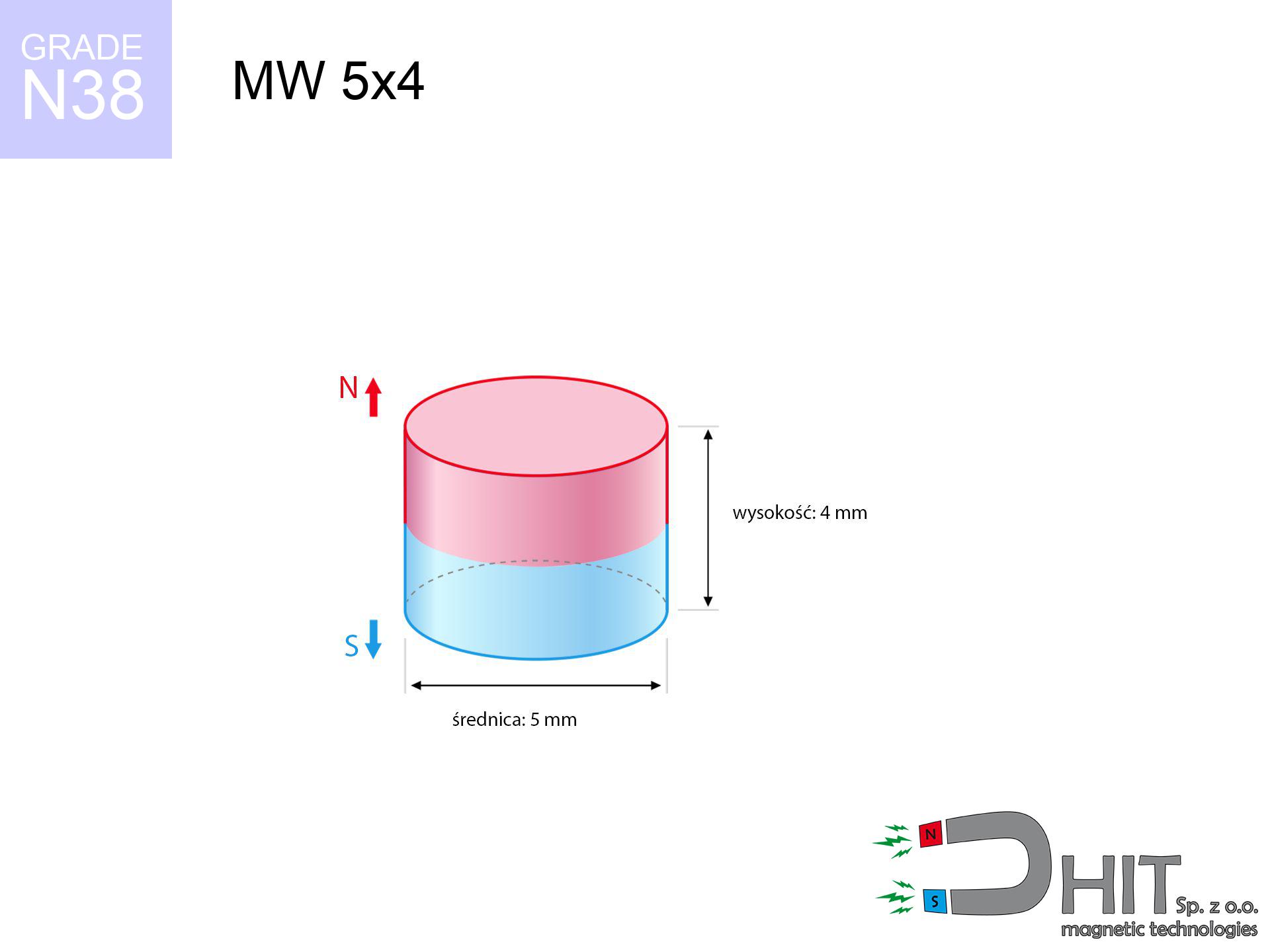
MW 5x4 / N38 - cylindrical magnet
cylindrical magnet
Catalog no 010089
GTIN/EAN: 5906301810889
Diameter Ø
5 mm [±0,1 mm]
Height
4 mm [±0,1 mm]
Weight
0.59 g
Magnetization Direction
↑ axial
Load capacity
0.84 kg / 8.24 N
Magnetic Induction
524.45 mT / 5244 Gs
Coating
[NiCuNi] Nickel
0.369 ZŁ with VAT / pcs + price for transport
0.300 ZŁ net + 23% VAT / pcs
bulk discounts:
Need more?
Contact us by phone
+48 22 499 98 98
if you prefer send us a note through
request form
the contact page.
Force and appearance of a magnet can be tested with our
modular calculator.
Order by 14:00 and we’ll ship today!
Technical details - MW 5x4 / N38 - cylindrical magnet
Specification / characteristics - MW 5x4 / N38 - cylindrical magnet
| properties | values |
|---|---|
| Cat. no. | 010089 |
| GTIN/EAN | 5906301810889 |
| Production/Distribution | Dhit sp. z o.o. |
| Country of origin | Poland / China / Germany |
| Customs code | 85059029 |
| Diameter Ø | 5 mm [±0,1 mm] |
| Height | 4 mm [±0,1 mm] |
| Weight | 0.59 g |
| Magnetization Direction | ↑ axial |
| Load capacity ~ ? | 0.84 kg / 8.24 N |
| Magnetic Induction ~ ? | 524.45 mT / 5244 Gs |
| Coating | [NiCuNi] Nickel |
| Manufacturing Tolerance | ±0.1 mm |
Magnetic properties of material N38
| properties | values | units |
|---|---|---|
| remenance Br [min. - max.] ? | 12.2-12.6 | kGs |
| remenance Br [min. - max.] ? | 1220-1260 | mT |
| coercivity bHc ? | 10.8-11.5 | kOe |
| coercivity bHc ? | 860-915 | kA/m |
| actual internal force iHc | ≥ 12 | kOe |
| actual internal force iHc | ≥ 955 | kA/m |
| energy density [min. - max.] ? | 36-38 | BH max MGOe |
| energy density [min. - max.] ? | 287-303 | BH max KJ/m |
| max. temperature ? | ≤ 80 | °C |
Physical properties of sintered neodymium magnets Nd2Fe14B at 20°C
| properties | values | units |
|---|---|---|
| Vickers hardness | ≥550 | Hv |
| Density | ≥7.4 | g/cm3 |
| Curie Temperature TC | 312 - 380 | °C |
| Curie Temperature TF | 593 - 716 | °F |
| Specific resistance | 150 | μΩ⋅cm |
| Bending strength | 250 | MPa |
| Compressive strength | 1000~1100 | MPa |
| Thermal expansion parallel (∥) to orientation (M) | (3-4) x 10-6 | °C-1 |
| Thermal expansion perpendicular (⊥) to orientation (M) | -(1-3) x 10-6 | °C-1 |
| Young's modulus | 1.7 x 10⁴ | kg/mm² |
Technical analysis of the magnet - report
These values represent the outcome of a mathematical simulation. Results rely on algorithms for the material Nd2Fe14B. Actual conditions may differ from theoretical values. Please consider these calculations as a reference point during assembly planning.
Table 1: Static pull force (force vs gap) - interaction chart
MW 5x4 / N38
| Distance (mm) | Induction (Gauss) / mT | Pull Force (kg/lbs/g/N) | Risk Status |
|---|---|---|---|
| 0 mm |
5236 Gs
523.6 mT
|
0.84 kg / 1.85 lbs
840.0 g / 8.2 N
|
low risk |
| 1 mm |
3243 Gs
324.3 mT
|
0.32 kg / 0.71 lbs
322.1 g / 3.2 N
|
low risk |
| 2 mm |
1850 Gs
185.0 mT
|
0.10 kg / 0.23 lbs
104.8 g / 1.0 N
|
low risk |
| 3 mm |
1076 Gs
107.6 mT
|
0.04 kg / 0.08 lbs
35.5 g / 0.3 N
|
low risk |
| 5 mm |
428 Gs
42.8 mT
|
0.01 kg / 0.01 lbs
5.6 g / 0.1 N
|
low risk |
| 10 mm |
89 Gs
8.9 mT
|
0.00 kg / 0.00 lbs
0.2 g / 0.0 N
|
low risk |
| 15 mm |
31 Gs
3.1 mT
|
0.00 kg / 0.00 lbs
0.0 g / 0.0 N
|
low risk |
| 20 mm |
15 Gs
1.5 mT
|
0.00 kg / 0.00 lbs
0.0 g / 0.0 N
|
low risk |
| 30 mm |
5 Gs
0.5 mT
|
0.00 kg / 0.00 lbs
0.0 g / 0.0 N
|
low risk |
| 50 mm |
1 Gs
0.1 mT
|
0.00 kg / 0.00 lbs
0.0 g / 0.0 N
|
low risk |
Table 2: Vertical capacity (wall)
MW 5x4 / N38
| Distance (mm) | Friction coefficient | Pull Force (kg/lbs/g/N) |
|---|---|---|
| 0 mm | Stal (~0.2) |
0.17 kg / 0.37 lbs
168.0 g / 1.6 N
|
| 1 mm | Stal (~0.2) |
0.06 kg / 0.14 lbs
64.0 g / 0.6 N
|
| 2 mm | Stal (~0.2) |
0.02 kg / 0.04 lbs
20.0 g / 0.2 N
|
| 3 mm | Stal (~0.2) |
0.01 kg / 0.02 lbs
8.0 g / 0.1 N
|
| 5 mm | Stal (~0.2) |
0.00 kg / 0.00 lbs
2.0 g / 0.0 N
|
| 10 mm | Stal (~0.2) |
0.00 kg / 0.00 lbs
0.0 g / 0.0 N
|
| 15 mm | Stal (~0.2) |
0.00 kg / 0.00 lbs
0.0 g / 0.0 N
|
| 20 mm | Stal (~0.2) |
0.00 kg / 0.00 lbs
0.0 g / 0.0 N
|
| 30 mm | Stal (~0.2) |
0.00 kg / 0.00 lbs
0.0 g / 0.0 N
|
| 50 mm | Stal (~0.2) |
0.00 kg / 0.00 lbs
0.0 g / 0.0 N
|
Table 3: Vertical assembly (shearing) - behavior on slippery surfaces
MW 5x4 / N38
| Surface type | Friction coefficient / % Mocy | Max load (kg/lbs/g/N) |
|---|---|---|
| Raw steel |
µ = 0.3
30% Nominalnej Siły
|
0.25 kg / 0.56 lbs
252.0 g / 2.5 N
|
| Painted steel (standard) |
µ = 0.2
20% Nominalnej Siły
|
0.17 kg / 0.37 lbs
168.0 g / 1.6 N
|
| Oily/slippery steel |
µ = 0.1
10% Nominalnej Siły
|
0.08 kg / 0.19 lbs
84.0 g / 0.8 N
|
| Magnet with anti-slip rubber |
µ = 0.5
50% Nominalnej Siły
|
0.42 kg / 0.93 lbs
420.0 g / 4.1 N
|
Table 4: Material efficiency (substrate influence) - power losses
MW 5x4 / N38
| Steel thickness (mm) | % power | Real pull force (kg/lbs/g/N) |
|---|---|---|
| 0.5 mm |
|
0.08 kg / 0.19 lbs
84.0 g / 0.8 N
|
| 1 mm |
|
0.21 kg / 0.46 lbs
210.0 g / 2.1 N
|
| 2 mm |
|
0.42 kg / 0.93 lbs
420.0 g / 4.1 N
|
| 3 mm |
|
0.63 kg / 1.39 lbs
630.0 g / 6.2 N
|
| 5 mm |
|
0.84 kg / 1.85 lbs
840.0 g / 8.2 N
|
| 10 mm |
|
0.84 kg / 1.85 lbs
840.0 g / 8.2 N
|
| 11 mm |
|
0.84 kg / 1.85 lbs
840.0 g / 8.2 N
|
| 12 mm |
|
0.84 kg / 1.85 lbs
840.0 g / 8.2 N
|
Table 5: Thermal resistance (material behavior) - resistance threshold
MW 5x4 / N38
| Ambient temp. (°C) | Power loss | Remaining pull (kg/lbs/g/N) | Status |
|---|---|---|---|
| 20 °C | 0.0% |
0.84 kg / 1.85 lbs
840.0 g / 8.2 N
|
OK |
| 40 °C | -2.2% |
0.82 kg / 1.81 lbs
821.5 g / 8.1 N
|
OK |
| 60 °C | -4.4% |
0.80 kg / 1.77 lbs
803.0 g / 7.9 N
|
OK |
| 80 °C | -6.6% |
0.78 kg / 1.73 lbs
784.6 g / 7.7 N
|
|
| 100 °C | -28.8% |
0.60 kg / 1.32 lbs
598.1 g / 5.9 N
|
Table 6: Magnet-Magnet interaction (attraction) - forces in the system
MW 5x4 / N38
| Gap (mm) | Attraction (kg/lbs) (N-S) | Lateral Force (kg/lbs/g/N) | Repulsion (kg/lbs) (N-N) |
|---|---|---|---|
| 0 mm |
3.32 kg / 7.32 lbs
5 894 Gs
|
0.50 kg / 1.10 lbs
498 g / 4.9 N
|
N/A |
| 1 mm |
2.14 kg / 4.72 lbs
8 408 Gs
|
0.32 kg / 0.71 lbs
321 g / 3.1 N
|
1.93 kg / 4.24 lbs
~0 Gs
|
| 2 mm |
1.27 kg / 2.81 lbs
6 486 Gs
|
0.19 kg / 0.42 lbs
191 g / 1.9 N
|
1.15 kg / 2.53 lbs
~0 Gs
|
| 3 mm |
0.73 kg / 1.61 lbs
4 909 Gs
|
0.11 kg / 0.24 lbs
109 g / 1.1 N
|
0.66 kg / 1.45 lbs
~0 Gs
|
| 5 mm |
0.24 kg / 0.53 lbs
2 805 Gs
|
0.04 kg / 0.08 lbs
36 g / 0.4 N
|
0.21 kg / 0.47 lbs
~0 Gs
|
| 10 mm |
0.02 kg / 0.05 lbs
857 Gs
|
0.00 kg / 0.01 lbs
3 g / 0.0 N
|
0.02 kg / 0.04 lbs
~0 Gs
|
| 20 mm |
0.00 kg / 0.00 lbs
177 Gs
|
0.00 kg / 0.00 lbs
0 g / 0.0 N
|
0.00 kg / 0.00 lbs
~0 Gs
|
| 50 mm |
0.00 kg / 0.00 lbs
16 Gs
|
0.00 kg / 0.00 lbs
0 g / 0.0 N
|
0.00 kg / 0.00 lbs
~0 Gs
|
| 60 mm |
0.00 kg / 0.00 lbs
9 Gs
|
0.00 kg / 0.00 lbs
0 g / 0.0 N
|
0.00 kg / 0.00 lbs
~0 Gs
|
| 70 mm |
0.00 kg / 0.00 lbs
6 Gs
|
0.00 kg / 0.00 lbs
0 g / 0.0 N
|
0.00 kg / 0.00 lbs
~0 Gs
|
| 80 mm |
0.00 kg / 0.00 lbs
4 Gs
|
0.00 kg / 0.00 lbs
0 g / 0.0 N
|
0.00 kg / 0.00 lbs
~0 Gs
|
| 90 mm |
0.00 kg / 0.00 lbs
3 Gs
|
0.00 kg / 0.00 lbs
0 g / 0.0 N
|
0.00 kg / 0.00 lbs
~0 Gs
|
| 100 mm |
0.00 kg / 0.00 lbs
2 Gs
|
0.00 kg / 0.00 lbs
0 g / 0.0 N
|
0.00 kg / 0.00 lbs
~0 Gs
|
Table 7: Hazards (implants) - precautionary measures
MW 5x4 / N38
| Object / Device | Limit (Gauss) / mT | Safe distance |
|---|---|---|
| Pacemaker | 5 Gs (0.5 mT) | 3.0 cm |
| Hearing aid | 10 Gs (1.0 mT) | 2.5 cm |
| Timepiece | 20 Gs (2.0 mT) | 2.0 cm |
| Mobile device | 40 Gs (4.0 mT) | 1.5 cm |
| Car key | 50 Gs (5.0 mT) | 1.5 cm |
| Payment card | 400 Gs (40.0 mT) | 1.0 cm |
| HDD hard drive | 600 Gs (60.0 mT) | 0.5 cm |
Table 8: Dynamics (kinetic energy) - collision effects
MW 5x4 / N38
| Start from (mm) | Speed (km/h) | Energy (J) | Predicted outcome |
|---|---|---|---|
| 10 mm |
38.06 km/h
(10.57 m/s)
|
0.03 J | |
| 30 mm |
65.91 km/h
(18.31 m/s)
|
0.10 J | |
| 50 mm |
85.09 km/h
(23.64 m/s)
|
0.16 J | |
| 100 mm |
120.34 km/h
(33.43 m/s)
|
0.33 J |
Table 9: Corrosion resistance
MW 5x4 / N38
| Technical parameter | Value / Description |
|---|---|
| Coating type | [NiCuNi] Nickel |
| Layer structure | Nickel - Copper - Nickel |
| Layer thickness | 10-20 µm |
| Salt spray test (SST) ? | 24 h |
| Recommended environment | Indoors only (dry) |
Table 10: Electrical data (Flux)
MW 5x4 / N38
| Parameter | Value | SI Unit / Description |
|---|---|---|
| Magnetic Flux | 1 046 Mx | 10.5 µWb |
| Pc Coefficient | 0.79 | High (Stable) |
Table 11: Hydrostatics and buoyancy
MW 5x4 / N38
| Environment | Effective steel pull | Effect |
|---|---|---|
| Air (land) | 0.84 kg | Standard |
| Water (riverbed) |
0.96 kg
(+0.12 kg buoyancy gain)
|
+14.5% |
1. Sliding resistance
*Caution: On a vertical wall, the magnet holds only a fraction of its perpendicular strength.
2. Steel thickness impact
*Thin metal sheet (e.g. 0.5mm PC case) drastically limits the holding force.
3. Thermal stability
*For N38 grade, the max working temp is 80°C.
4. Demagnetization curve and operating point (B-H)
chart generated for the permeance coefficient Pc (Permeance Coefficient) = 0.79
The chart above illustrates the magnetic characteristics of the material within the second quadrant of the hysteresis loop. The solid red line represents the demagnetization curve (material potential), while the dashed blue line is the load line based on the magnet's geometry. The Pc (Permeance Coefficient), also known as the load line slope, is a dimensionless value that describes the relationship between the magnet's shape and its magnetic stability. The intersection of these two lines (the black dot) is the operating point — it determines the actual magnetic flux density generated by the magnet in this specific configuration. A higher Pc value means the magnet is more 'slender' (tall relative to its area), resulting in a higher operating point and better resistance to irreversible demagnetization caused by external fields or temperature. A value of 0.42 is relatively low (typical for flat magnets), meaning the operating point is closer to the 'knee' of the curve — caution is advised when operating at temperatures near the maximum limit to avoid strength loss.
Elemental analysis
| iron (Fe) | 64% – 68% |
| neodymium (Nd) | 29% – 32% |
| boron (B) | 1.1% – 1.2% |
| dysprosium (Dy) | 0.5% – 2.0% |
| coating (Ni-Cu-Ni) | < 0.05% |
Environmental data
| recyclability (EoL) | 100% |
| recycled raw materials | ~10% (pre-cons) |
| carbon footprint | low / zredukowany |
| waste code (EWC) | 16 02 16 |
View more deals

![UI 45x13x6 [Z323] / N38 - badge holder](https://cdn3.dhit.pl/graphics/products/ui45x13x6-z323-fap.jpg "UI 45x13x6 [Z323] / N38 - badge holder")


Advantages and disadvantages of neodymium magnets.
Pros
- They have constant strength, and over more than 10 years their attraction force decreases symbolically – ~1% (in testing),
- Magnets very well resist against demagnetization caused by foreign field sources,
- By applying a decorative coating of nickel, the element has an modern look,
- They are known for high magnetic induction at the operating surface, which improves attraction properties,
- Due to their durability and thermal resistance, neodymium magnets are capable of operate (depending on the shape) even at high temperatures reaching 230°C or more...
- Thanks to flexibility in forming and the capacity to adapt to complex applications,
- Fundamental importance in high-tech industry – they are used in hard drives, electric motors, medical devices, and technologically advanced constructions.
- Compactness – despite small sizes they offer powerful magnetic field, making them ideal for precision applications
Cons
- To avoid cracks upon strong impacts, we suggest using special steel housings. Such a solution secures the magnet and simultaneously increases its durability.
- Neodymium magnets lose power when exposed to high temperatures. After reaching 80°C, many of them experience permanent weakening of power (a factor is the shape and dimensions of the magnet). We offer magnets specially adapted to work at temperatures up to 230°C marked [AH], which are very resistant to heat
- They oxidize in a humid environment. For use outdoors we recommend using waterproof magnets e.g. in rubber, plastic
- Limited possibility of making threads in the magnet and complex forms - preferred is a housing - magnetic holder.
- Health risk related to microscopic parts of magnets can be dangerous, in case of ingestion, which gains importance in the context of child safety. Furthermore, small components of these magnets are able to complicate diagnosis medical in case of swallowing.
- Higher cost of purchase is one of the disadvantages compared to ceramic magnets, especially in budget applications
Holding force characteristics
Maximum holding power of the magnet – what it depends on?
- with the contact of a sheet made of special test steel, ensuring full magnetic saturation
- possessing a thickness of at least 10 mm to avoid saturation
- with a surface free of scratches
- with direct contact (no coatings)
- under vertical force vector (90-degree angle)
- at room temperature
What influences lifting capacity in practice
- Space between surfaces – even a fraction of a millimeter of distance (caused e.g. by veneer or unevenness) drastically reduces the pulling force, often by half at just 0.5 mm.
- Force direction – note that the magnet holds strongest perpendicularly. Under shear forces, the capacity drops drastically, often to levels of 20-30% of the maximum value.
- Metal thickness – thin material does not allow full use of the magnet. Part of the magnetic field penetrates through instead of generating force.
- Material composition – not every steel reacts the same. High carbon content weaken the attraction effect.
- Base smoothness – the smoother and more polished the surface, the better the adhesion and higher the lifting capacity. Roughness creates an air distance.
- Temperature influence – hot environment weakens magnetic field. Too high temperature can permanently damage the magnet.
Holding force was checked on the plate surface of 20 mm thickness, when the force acted perpendicularly, however under attempts to slide the magnet the lifting capacity is smaller. Moreover, even a small distance between the magnet’s surface and the plate decreases the holding force.
Precautions when working with neodymium magnets
Immense force
Handle magnets with awareness. Their powerful strength can shock even experienced users. Stay alert and respect their power.
Protective goggles
Watch out for shards. Magnets can fracture upon uncontrolled impact, ejecting shards into the air. We recommend safety glasses.
Crushing risk
Big blocks can break fingers instantly. Under no circumstances put your hand between two attracting surfaces.
Choking Hazard
Only for adults. Tiny parts pose a choking risk, leading to intestinal necrosis. Keep out of reach of children and animals.
Allergic reactions
Nickel alert: The Ni-Cu-Ni coating consists of nickel. If skin irritation occurs, immediately stop handling magnets and use protective gear.
GPS Danger
Navigation devices and mobile phones are highly susceptible to magnetic fields. Direct contact with a powerful NdFeB magnet can decalibrate the sensors in your phone.
Mechanical processing
Machining of neodymium magnets carries a risk of fire risk. Neodymium dust oxidizes rapidly with oxygen and is hard to extinguish.
Implant safety
People with a ICD must maintain an large gap from magnets. The magnetic field can stop the functioning of the life-saving device.
Data carriers
Very strong magnetic fields can corrupt files on credit cards, HDDs, and storage devices. Keep a distance of min. 10 cm.
Maximum temperature
Regular neodymium magnets (N-type) undergo demagnetization when the temperature goes above 80°C. This process is irreversible.
Tabela kosztu i czasu dostawy
Płatność przed wysyłką:

GLS kurier
Przesyłka będzie u Ciebie za 2-3 dni
14.99 ZŁ

InPost Paczkomaty 24/7
Przesyłka będzie u Ciebie za 1-2 dni
12.30 ZŁ
Płatność przy odbiorze (pobranie):
GLS kurier
Przesyłka będzie u Ciebie za 1-2 dni
23.00 ZŁ
Rate the product
Your rating