

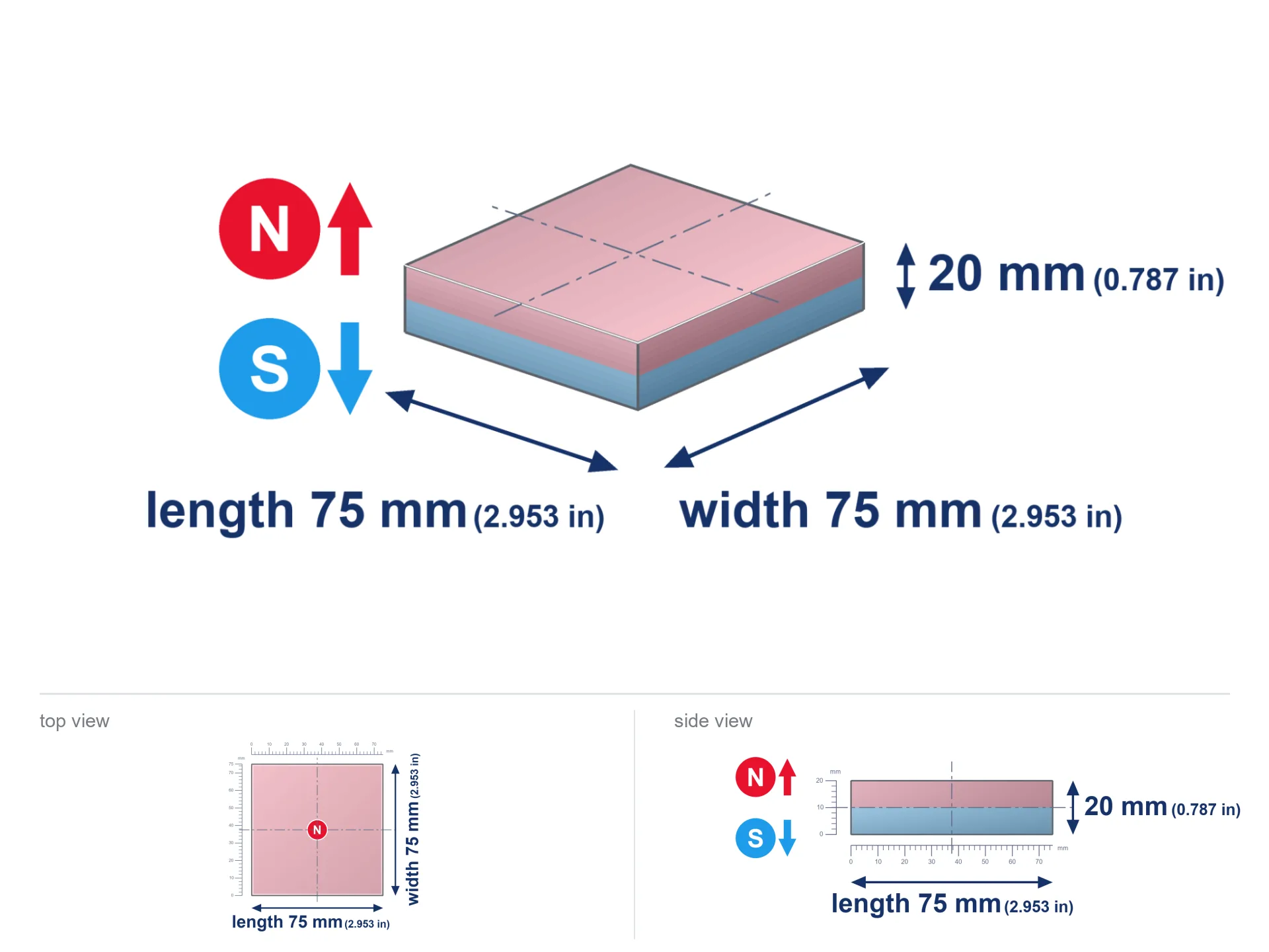
MPL 75x75x20 / N38 - lamellar magnet
lamellar magnet
Catalog no 020587
GTIN/EAN: 5906301815808
- length
- 75 mm [±0,1 mm]
- Width
- 75 mm [±0,1 mm]
- Height
- 20 mm [±0,1 mm]
- Weight
- 843.75 g
- Magnetization Direction
- ↑ axial
- Coating
- [NiCuNi] Nickel
How we measure these parameters — certificates and measurements
259.07 zł net / pcs
318.66 zł with VAT (23% VAT) / pcs
bulk discounts:
Need more?Frequently asked questions
What pull rating should I choose for a workshop block magnet?
Are block neodymium magnets available in more durable versions?
How should I choose block magnets for mounting a structure?
Engineering report for this magnet
Full PDF analysis: pull and shear force, effect of distance, temperature and plate thickness, safety distances and the demagnetization curve.
Call us now
+48 888 99 98 98
alternatively let us know using
contact form
the contact section.
Specifications and structure of a neodymium magnet can be estimated using our
power calculator.
Order by 14:00 and we’ll ship today!
Technical specification - MPL 75x75x20 / N38 - lamellar magnet
Specification / characteristics - MPL 75x75x20 / N38 - lamellar magnet
| properties | values |
|---|---|
| Cat. no. | 020587 |
| GTIN/EAN | 5906301815808 |
| Distributor | Dhit sp. z o.o. |
| Country of origin | Poland / China / Germany |
| Customs code | 85059029 |
| length | 75 mm [±0,1 mm] |
| Width | 75 mm [±0,1 mm] |
| Height | 20 mm [±0,1 mm] |
| Weight | 843.75 g |
| Magnetization Direction | ↑ axial |
| Load capacity ~ ? | 120.18 kg / 1178.56 N |
| Magnetic Induction ~ ? | 267.76 mT / 2678 Gs |
| Coating | [NiCuNi] Nickel |
| Manufacturing Tolerance | ±0.1 mm |
Magnetic properties of material N38
| properties | values | units |
|---|---|---|
| Remanence Br ? | 12.2-12.6 | kGs |
| Remanence Br ? | 1220-1260 | mT |
| Coercivity bHc ? | 10.8-11.5 | kOe |
| Coercivity bHc ? | 860-915 | kA/m |
| Intrinsic coercivity iHc | ≥ 12 | kOe |
| Intrinsic coercivity iHc | ≥ 955 | kA/m |
| Energy product BHmax ? | 36-38 | BH max MGOe |
| Energy product BHmax ? | 287-303 | BH max KJ/m |
| Maximum working temperature ? | ≤ 80 | °C |
Physical properties of sintered neodymium magnets Nd2Fe14B at 20°C
| properties | values | units |
|---|---|---|
| Vickers hardness | ≥550 | Hv |
| Density | ≥7.4 | g/cm3 |
| Curie Temperature TC | 310 | °C |
| Curie Temperature TF | 590 | °F |
| Specific resistance | 150 | μΩ⋅cm |
| Bending strength | 250 | MPa |
| Compressive strength | 1000~1100 | MPa |
| Thermal expansion parallel (∥) to orientation (M) | (3-4) x 10-6 | °C-1 |
| Thermal expansion perpendicular (⊥) to orientation (M) | -(1-3) x 10-6 | °C-1 |
| Young's modulus | 1.7 x 10⁴ | kg/mm² |
Technical analysis of the assembly - report
Presented data are the outcome of a mathematical analysis. Results rely on algorithms for the material Nd2Fe14B. Operational performance may differ from theoretical values. Treat these calculations as a reference point during assembly planning.
Table 1: Static pull force (pull vs distance) - interaction chart
MPL 75x75x20 / N38
| Distance (mm) | Induction (Gauss) / mT | Pull Force (kg/lbs/g/N) | Risk Status |
|---|---|---|---|
| 0 mm |
2677 Gs
267.7 mT
|
120.18 kg / 264.95 LBS
120180.0 g / 1179.0 N
|
dangerous! |
| 1 mm |
2636 Gs
263.6 mT
|
116.48 kg / 256.80 LBS
116482.6 g / 1142.7 N
|
dangerous! |
| 2 mm |
2591 Gs
259.1 mT
|
112.56 kg / 248.16 LBS
112563.5 g / 1104.2 N
|
dangerous! |
| 3 mm |
2544 Gs
254.4 mT
|
108.49 kg / 239.19 LBS
108494.9 g / 1064.3 N
|
dangerous! |
| 5 mm |
2443 Gs
244.3 mT
|
100.05 kg / 220.57 LBS
100049.7 g / 981.5 N
|
dangerous! |
| 10 mm |
2165 Gs
216.5 mT
|
78.61 kg / 173.29 LBS
78605.1 g / 771.1 N
|
dangerous! |
| 15 mm |
1877 Gs
187.7 mT
|
59.05 kg / 130.18 LBS
59049.0 g / 579.3 N
|
dangerous! |
| 20 mm |
1601 Gs
160.1 mT
|
42.96 kg / 94.71 LBS
42960.5 g / 421.4 N
|
dangerous! |
| 30 mm |
1135 Gs
113.5 mT
|
21.59 kg / 47.59 LBS
21585.3 g / 211.8 N
|
dangerous! |
| 50 mm |
566 Gs
56.6 mT
|
5.37 kg / 11.84 LBS
5369.5 g / 52.7 N
|
medium risk |
Table 2: Shear hold (wall)
MPL 75x75x20 / N38
| Distance (mm) | Friction coefficient | Pull Force (kg/lbs/g/N) |
|---|---|---|
| 0 mm | Raw steel (µ ≈ 0.2) |
24.04 kg / 52.99 LBS
24036.0 g / 235.8 N
|
| 1 mm | Raw steel (µ ≈ 0.2) |
23.30 kg / 51.36 LBS
23296.0 g / 228.5 N
|
| 2 mm | Raw steel (µ ≈ 0.2) |
22.51 kg / 49.63 LBS
22512.0 g / 220.8 N
|
| 3 mm | Raw steel (µ ≈ 0.2) |
21.70 kg / 47.84 LBS
21698.0 g / 212.9 N
|
| 5 mm | Raw steel (µ ≈ 0.2) |
20.01 kg / 44.11 LBS
20010.0 g / 196.3 N
|
| 10 mm | Raw steel (µ ≈ 0.2) |
15.72 kg / 34.66 LBS
15722.0 g / 154.2 N
|
| 15 mm | Raw steel (µ ≈ 0.2) |
11.81 kg / 26.04 LBS
11810.0 g / 115.9 N
|
| 20 mm | Raw steel (µ ≈ 0.2) |
8.59 kg / 18.94 LBS
8592.0 g / 84.3 N
|
| 30 mm | Raw steel (µ ≈ 0.2) |
4.32 kg / 9.52 LBS
4318.0 g / 42.4 N
|
| 50 mm | Raw steel (µ ≈ 0.2) |
1.07 kg / 2.37 LBS
1074.0 g / 10.5 N
|
Table 3: Wall mounting (shearing) - vertical pull
MPL 75x75x20 / N38
| Surface type | Friction coefficient / % | Max load (kg/lbs/g/N) |
|---|---|---|
| Raw steel |
µ = 0.3
30% of nominal force
|
36.05 kg / 79.49 LBS
36054.0 g / 353.7 N
|
| Painted steel (standard) |
µ = 0.2
20% of nominal force
|
24.04 kg / 52.99 LBS
24036.0 g / 235.8 N
|
| Oily/slippery steel |
µ = 0.1
10% of nominal force
|
12.02 kg / 26.50 LBS
12018.0 g / 117.9 N
|
| Magnet with anti-slip rubber |
µ = 0.5
50% of nominal force
|
60.09 kg / 132.48 LBS
60090.0 g / 589.5 N
|
Table 4: Steel thickness (saturation) - sheet metal selection
MPL 75x75x20 / N38
| Steel thickness (mm) | % power | Real pull force (kg/lbs/g/N) |
|---|---|---|
| 0.5 mm |
|
4.01 kg / 8.83 LBS
4006.0 g / 39.3 N
|
| 1 mm |
|
10.01 kg / 22.08 LBS
10015.0 g / 98.2 N
|
| 2 mm |
|
20.03 kg / 44.16 LBS
20030.0 g / 196.5 N
|
| 3 mm |
|
30.05 kg / 66.24 LBS
30045.0 g / 294.7 N
|
| 5 mm |
|
50.08 kg / 110.40 LBS
50075.0 g / 491.2 N
|
| 10 mm |
|
100.15 kg / 220.79 LBS
100150.0 g / 982.5 N
|
| 11 mm |
|
110.16 kg / 242.87 LBS
110165.0 g / 1080.7 N
|
| 12 mm |
|
120.18 kg / 264.95 LBS
120180.0 g / 1179.0 N
|
Table 5: Working in heat (material behavior) - power drop
MPL 75x75x20 / N38
| Magnet temperature (°C) | Force change relative to 20°C | Remaining pull (kg/lbs/g/N) | Status |
|---|---|---|---|
| 20 °C | 0.0% |
120.18 kg / 264.95 LBS
120180.0 g / 1179.0 N
|
Estimate |
| 40 °C | -4.4% |
114.95 kg / 253.42 LBS
114950.2 g / 1127.7 N
|
Estimate |
| 60 °C | -8.6% |
109.84 kg / 242.15 LBS
109836.8 g / 1077.5 N
|
Estimate |
| 80 °C | -12.8% |
104.84 kg / 231.13 LBS
104839.7 g / 1028.5 N
|
Material limit |
| 100 °C | — | — | Out of range — no model |
Table 6: Two magnets (attraction) - field collision
MPL 75x75x20 / N38
| Gap (mm) | Attraction (kg/lbs) (N-S) | Shear Strength (kg/lbs/g/N) | Repulsion (kg/lbs) (N-N) |
|---|---|---|---|
| 0 mm |
248.60 kg / 548.07 LBS
4 278 Gs
|
37.29 kg / 82.21 LBS
37290 g / 365.8 N
|
N/A |
| 1 mm |
244.87 kg / 539.84 LBS
5 315 Gs
|
36.73 kg / 80.98 LBS
36730 g / 360.3 N
|
220.38 kg / 485.86 LBS
~0 Gs
|
| 2 mm |
240.95 kg / 531.21 LBS
5 272 Gs
|
36.14 kg / 79.68 LBS
36143 g / 354.6 N
|
216.86 kg / 478.09 LBS
~0 Gs
|
| 3 mm |
236.94 kg / 522.37 LBS
5 228 Gs
|
35.54 kg / 78.36 LBS
35542 g / 348.7 N
|
213.25 kg / 470.13 LBS
~0 Gs
|
| 5 mm |
228.67 kg / 504.14 LBS
5 136 Gs
|
34.30 kg / 75.62 LBS
34301 g / 336.5 N
|
205.81 kg / 453.72 LBS
~0 Gs
|
| 10 mm |
206.96 kg / 456.27 LBS
4 886 Gs
|
31.04 kg / 68.44 LBS
31044 g / 304.5 N
|
186.26 kg / 410.64 LBS
~0 Gs
|
| 20 mm |
162.60 kg / 358.47 LBS
4 331 Gs
|
24.39 kg / 53.77 LBS
24390 g / 239.3 N
|
146.34 kg / 322.63 LBS
~0 Gs
|
| 50 mm |
63.34 kg / 139.64 LBS
2 703 Gs
|
9.50 kg / 20.95 LBS
9501 g / 93.2 N
|
57.01 kg / 125.68 LBS
~0 Gs
|
| 60 mm |
44.65 kg / 98.44 LBS
2 269 Gs
|
6.70 kg / 14.77 LBS
6698 g / 65.7 N
|
40.19 kg / 88.59 LBS
~0 Gs
|
| 70 mm |
31.36 kg / 69.13 LBS
1 902 Gs
|
4.70 kg / 10.37 LBS
4703 g / 46.1 N
|
28.22 kg / 62.22 LBS
~0 Gs
|
| 80 mm |
22.05 kg / 48.62 LBS
1 595 Gs
|
3.31 kg / 7.29 LBS
3308 g / 32.5 N
|
19.85 kg / 43.76 LBS
~0 Gs
|
| 90 mm |
15.59 kg / 34.37 LBS
1 341 Gs
|
2.34 kg / 5.16 LBS
2339 g / 22.9 N
|
14.03 kg / 30.94 LBS
~0 Gs
|
| 100 mm |
11.11 kg / 24.49 LBS
1 132 Gs
|
1.67 kg / 3.67 LBS
1666 g / 16.3 N
|
10.00 kg / 22.04 LBS
~0 Gs
|
Table 7: Axial field levels — not safety zones
MPL 75x75x20 / N38
| Field level (Gs) | mT | Model distance (cm) |
|---|---|---|
| < 5 Gs | < 0.5 mT | 34.5 cm |
| < 10 Gs | < 1.0 mT | 27.0 cm |
| < 20 Gs | < 2.0 mT | 21.0 cm |
| < 40 Gs | < 4.0 mT | 16.5 cm |
| < 50 Gs | < 5.0 mT | 15.0 cm |
| < 400 Gs | < 40.0 mT | 6.5 cm |
| < 600 Gs | < 60.0 mT | 5.0 cm |
Table 8: Collisions (cracking risk) - warning
MPL 75x75x20 / N38
| Start from (mm) | Speed (km/h) | Energy (J) | Predicted outcome |
|---|---|---|---|
| 10 mm |
17.35 km/h
(4.82 m/s)
|
9.80 J | |
| 30 mm |
23.97 km/h
(6.66 m/s)
|
18.71 J | |
| 50 mm |
25.39 km/h
(7.05 m/s)
|
20.98 J | |
| 100 mm |
25.87 km/h
(7.19 m/s)
|
21.79 J |
Table 9: Anti-corrosion coating durability
MPL 75x75x20 / N38
| Technical parameter | Value / Description |
|---|---|
| Coating type | [NiCuNi] Nickel |
| Layer structure | Nickel - Copper - Nickel |
| Layer thickness | 10-20 µm |
| Salt spray test (SST) ? | 24 h |
| Recommended environment | Indoors only (dry) |
Table 10: Electrical data (Flux)
MPL 75x75x20 / N38
| Parameter | Value | SI Unit / Description |
|---|---|---|
| Magnetic Flux | 167 290 Mx | 1672.9 µWb |
| Pc Coefficient | 0.33 | Low (Flat) |
Table 11: Physics of underwater searching
MPL 75x75x20 / N38
| Environment | Effective steel pull | Effect |
|---|---|---|
| Air (land) | 120.18 kg | Standard |
| Water (riverbed) |
137.61 kg
(+17.43 kg buoyancy gain)
|
+14.5% |
1. Sliding resistance
*Caution: On a vertical wall, the magnet retains merely approx. 20-30% of its perpendicular strength.
2. Plate thickness effect
*Thin metal sheet (e.g. computer case) drastically reduces the holding force.
3. Heat tolerance
N38: the maximum material working temperature is 80°C. Permitted conditions also depend on the shape and magnetic circuit.
4. Demagnetization curve and operating point (B-H)
chart generated for the permeance coefficient Pc (Permeance Coefficient) = 0.33
The chart above illustrates the magnetic characteristics of the material within the second quadrant of the hysteresis loop. The solid red line represents the demagnetization curve (material potential), while the dashed blue line is the load line based on the magnet's geometry. The Pc (Permeance Coefficient), also known as the load line slope, is a dimensionless value that describes the relationship between the magnet's shape and its magnetic stability. The intersection of these two lines (the black dot) is the operating point — it determines the actual magnetic flux density generated by the magnet in this specific configuration. A higher Pc value means the magnet is more 'slender' (tall relative to its area), resulting in a higher operating point and better resistance to irreversible demagnetization caused by external fields or temperature. A value of 0.42 is relatively low (typical for flat magnets), meaning the operating point is closer to the 'knee' of the curve — caution is advised when operating at temperatures near the maximum limit to avoid strength loss.
Chemical composition
| iron (Fe) | 64% – 68% |
| neodymium (Nd) | 29% – 32% |
| boron (B) | 1.1% – 1.2% |
| dysprosium (Dy) | 0.5% – 2.0% |
| coating (Ni-Cu-Ni) | < 0.05% |
Sustainability
| recyclability (EoL) | 100% |
| recycled raw materials | ~10% (pre-cons) |
| carbon footprint | low / zredukowany |
| waste code (EWC) | 16 02 16 |
Other offers

Advantages as well as disadvantages of Nd2Fe14B magnets.
Strengths
- They do not lose strength, even after approximately ten years – the drop in strength is only ~1% (theoretically),
- Magnets perfectly protect themselves against demagnetization caused by ambient magnetic noise,
- By using a lustrous coating of silver, the element acquires an aesthetic look,
- Magnetic induction on the working part of the magnet remains exceptional,
- Thanks to resistance to high temperature, they are able to function (depending on the form) even at temperatures up to 230°C and higher...
- In view of the option of flexible forming and adaptation to specialized needs, magnetic components can be manufactured in a variety of shapes and sizes, which expands the range of possible applications,
- Fundamental importance in modern industrial fields – they find application in computer drives, drive modules, diagnostic systems, and modern systems.
- Relatively small size with high pulling force – neodymium magnets offer strong magnetic field in tiny dimensions, which enables their usage in compact constructions
Cons
- Brittleness is one of their disadvantages. Upon intense impact they can break. We advise keeping them in a strong case, which not only protects them against impacts but also increases their durability
- Do not exceed this material temperature limit: 80°C. Overheating may permanently weaken the magnet.
- Due to the susceptibility of magnets to corrosion in a humid environment, we advise using waterproof magnets made of rubber, plastic or other material immune to moisture, in case of application outdoors
- Limited possibility of creating nuts in the magnet and complex forms - recommended is cover - magnet mounting.
- Health risk resulting from small fragments of magnets can be dangerous, in case of ingestion, which becomes key in the aspect of protecting the youngest. It is also worth noting that small components of these products are able to complicate diagnosis medical after entering the body.
- High unit price – neodymium magnets have a higher price than other types of magnets (e.g. ferrite), which increases costs of application in large quantities
Holding force characteristics
Maximum lifting capacity of the magnet – what affects it?
- with the application of a yoke made of low-carbon steel, ensuring maximum field concentration
- with a thickness minimum 10 mm
- with a plane cleaned and smooth
- with total lack of distance (without paint)
- during detachment in a direction perpendicular to the mounting surface
- at ambient temperature approx. 20 degrees Celsius
Practical lifting capacity: influencing factors
- Distance – the presence of foreign body (rust, dirt, gap) interrupts the magnetic circuit, which lowers power rapidly (even by 50% at 0.5 mm).
- Load vector – highest force is available only during pulling at a 90° angle. The shear force of the magnet along the plate is standardly many times smaller (approx. 1/5 of the lifting capacity).
- Wall thickness – thin material does not allow full use of the magnet. Magnetic flux passes through the material instead of converting into lifting capacity.
- Material type – the best choice is high-permeability steel. Stainless steels may generate lower lifting capacity.
- Surface condition – ground elements guarantee perfect abutment, which increases field saturation. Uneven metal weaken the grip.
- Temperature – temperature increase results in weakening of force. Check the thermal limit for a given model.
Holding force was measured on the plate surface of 20 mm thickness, when a perpendicular force was applied, whereas under shearing force the holding force is lower. Additionally, even a slight gap between the magnet’s surface and the plate decreases the lifting capacity.
Precautions when working with NdFeB magnets
Crushing risk
Mind your fingers. Two powerful magnets will snap together instantly with a force of several hundred kilograms, destroying everything in their path. Be careful!
Choking Hazard
Always store magnets out of reach of children. Ingestion danger is significant, and the consequences of magnets clamping inside the body are fatal.
Electronic hazard
Powerful magnetic fields can erase data on payment cards, hard drives, and other magnetic media. Keep a distance of at least 10 cm.
Life threat
Patients with a ICD have to keep an absolute distance from magnets. The magnetic field can disrupt the functioning of the implant.
Magnetic interference
Navigation devices and smartphones are extremely sensitive to magnetic fields. Direct contact with a powerful NdFeB magnet can permanently damage the sensors in your phone.
Dust is flammable
Powder created during machining of magnets is flammable. Do not drill into magnets without proper cooling and knowledge.
Respect the power
Exercise caution. Neodymium magnets attract from a distance and connect with huge force, often quicker than you can react.
Risk of cracking
Watch out for shards. Magnets can fracture upon violent connection, launching sharp fragments into the air. Wear goggles.
Sensitization to coating
Certain individuals experience a sensitization to nickel, which is the common plating for NdFeB magnets. Prolonged contact might lead to an allergic reaction. We recommend use protective gloves.
Heat warning
Do not exceed the maximum operating temperature stated in the specifications of the particular product. The limit depends on the material, geometry and operating arrangement; there is no single threshold for all neodymium magnets. Overheating can permanently weaken a magnet.
Tabela kosztu i czasu dostawy
Płatność przed wysyłką:

GLS kurier
Przesyłka będzie u Ciebie za 2-3 dni
14.99 ZŁ

InPost Paczkomaty 24/7
Przesyłka będzie u Ciebie za 1-2 dni
12.30 ZŁ
Płatność przy odbiorze (pobranie):
GLS kurier
Przesyłka będzie u Ciebie za 1-2 dni
23.00 ZŁ