

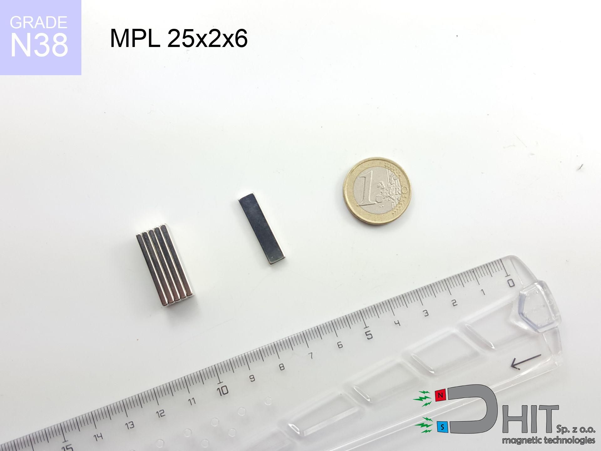
MPL 25x2x6 / N38 - lamellar magnet
lamellar magnet
Catalog no 020509
- length
- 25 mm [±0,1 mm]
- Width
- 2 mm [±0,1 mm]
- Height
- 6 mm [±0,1 mm]
- Weight
- 2.25 g
- Magnetization Direction
- ↑ axial
- Coating
- [NiCuNi] Nickel
How we measure these parameters — certificates and measurements
0.580 zł net / pcs
0.713 zł with VAT (23% VAT) / pcs
bulk discounts:
Need more?Frequently asked questions
What pull rating should I choose for a workshop block magnet?
Are block neodymium magnets available in more durable versions?
How should I choose block magnets for mounting a structure?
Engineering report for this magnet
Full PDF analysis: pull and shear force, effect of distance, temperature and plate thickness, safety distances and the demagnetization curve.
Call us now
+48 888 99 98 98
alternatively let us know using
contact form
the contact section.
Specifications and structure of a neodymium magnet can be estimated using our
power calculator.
Order by 14:00 and we’ll ship today!
Technical - MPL 25x2x6 / N38 - lamellar magnet
Specification / characteristics - MPL 25x2x6 / N38 - lamellar magnet
| properties | values |
|---|---|
| Cat. no. | 020509 |
| Production/Distribution | Dhit sp. z o.o. |
| Country of origin | Poland / China / Germany |
| Customs code | 85059029 |
| length | 25 mm [±0,1 mm] |
| Width | 2 mm [±0,1 mm] |
| Height | 6 mm [±0,1 mm] |
| Weight | 2.25 g |
| Magnetization Direction | ↑ axial |
| Load capacity ~ ? | 2.33 kg / 22.82 N |
| Magnetic Induction ~ ? | 558.90 mT / 5589 Gs |
| Coating | [NiCuNi] Nickel |
| Manufacturing Tolerance | ±0.1 mm |
Magnetic properties of material N38
| properties | values | units |
|---|---|---|
| Remanence Br ? | 12.2-12.6 | kGs |
| Remanence Br ? | 1220-1260 | mT |
| Coercivity bHc ? | 10.8-11.5 | kOe |
| Coercivity bHc ? | 860-915 | kA/m |
| Intrinsic coercivity iHc | ≥ 12 | kOe |
| Intrinsic coercivity iHc | ≥ 955 | kA/m |
| Energy product BHmax ? | 36-38 | BH max MGOe |
| Energy product BHmax ? | 287-303 | BH max KJ/m |
| Maximum working temperature ? | ≤ 80 | °C |
Physical properties of sintered neodymium magnets Nd2Fe14B at 20°C
| properties | values | units |
|---|---|---|
| Vickers hardness | ≥550 | Hv |
| Density | ≥7.4 | g/cm3 |
| Curie Temperature TC | 310 | °C |
| Curie Temperature TF | 590 | °F |
| Specific resistance | 150 | μΩ⋅cm |
| Bending strength | 250 | MPa |
| Compressive strength | 1000~1100 | MPa |
| Thermal expansion parallel (∥) to orientation (M) | (3-4) x 10-6 | °C-1 |
| Thermal expansion perpendicular (⊥) to orientation (M) | -(1-3) x 10-6 | °C-1 |
| Young's modulus | 1.7 x 10⁴ | kg/mm² |
Technical modeling of the magnet - technical parameters
These information constitute the direct effect of a engineering calculation. Values are based on algorithms for the class Nd2Fe14B. Real-world performance may differ. Treat these calculations as a supplementary guide for designers.
Table 1: Static pull force (pull vs distance) - interaction chart
MPL 25x2x6 / N38
| Distance (mm) | Induction (Gauss) / mT | Pull Force (kg/lbs/g/N) | Risk Status |
|---|---|---|---|
| 0 mm |
5574 Gs
557.4 mT
|
2.33 kg / 5.14 LBS
2330.0 g / 22.9 N
|
strong |
| 1 mm |
2599 Gs
259.9 mT
|
0.51 kg / 1.12 LBS
506.6 g / 5.0 N
|
safe |
| 2 mm |
1392 Gs
139.2 mT
|
0.15 kg / 0.32 LBS
145.3 g / 1.4 N
|
safe |
| 3 mm |
879 Gs
87.9 mT
|
0.06 kg / 0.13 LBS
58.0 g / 0.6 N
|
safe |
| 5 mm |
454 Gs
45.4 mT
|
0.02 kg / 0.03 LBS
15.5 g / 0.2 N
|
safe |
| 10 mm |
155 Gs
15.5 mT
|
0.00 kg / 0.00 LBS
1.8 g / 0.0 N
|
safe |
| 15 mm |
72 Gs
7.2 mT
|
0.00 kg / 0.00 LBS
0.4 g / 0.0 N
|
safe |
| 20 mm |
39 Gs
3.9 mT
|
0.00 kg / 0.00 LBS
0.1 g / 0.0 N
|
safe |
| 30 mm |
15 Gs
1.5 mT
|
0.00 kg / 0.00 LBS
0.0 g / 0.0 N
|
safe |
| 50 mm |
4 Gs
0.4 mT
|
0.00 kg / 0.00 LBS
0.0 g / 0.0 N
|
safe |
Table 2: Slippage load (wall)
MPL 25x2x6 / N38
| Distance (mm) | Friction coefficient | Pull Force (kg/lbs/g/N) |
|---|---|---|
| 0 mm | Raw steel (µ ≈ 0.2) |
0.47 kg / 1.03 LBS
466.0 g / 4.6 N
|
| 1 mm | Raw steel (µ ≈ 0.2) |
0.10 kg / 0.22 LBS
102.0 g / 1.0 N
|
| 2 mm | Raw steel (µ ≈ 0.2) |
0.03 kg / 0.07 LBS
30.0 g / 0.3 N
|
| 3 mm | Raw steel (µ ≈ 0.2) |
0.01 kg / 0.03 LBS
12.0 g / 0.1 N
|
| 5 mm | Raw steel (µ ≈ 0.2) |
0.00 kg / 0.01 LBS
4.0 g / 0.0 N
|
| 10 mm | Raw steel (µ ≈ 0.2) |
0.00 kg / 0.00 LBS
0.0 g / 0.0 N
|
| 15 mm | Raw steel (µ ≈ 0.2) |
0.00 kg / 0.00 LBS
0.0 g / 0.0 N
|
| 20 mm | Raw steel (µ ≈ 0.2) |
0.00 kg / 0.00 LBS
0.0 g / 0.0 N
|
| 30 mm | Raw steel (µ ≈ 0.2) |
0.00 kg / 0.00 LBS
0.0 g / 0.0 N
|
| 50 mm | Raw steel (µ ≈ 0.2) |
0.00 kg / 0.00 LBS
0.0 g / 0.0 N
|
Table 3: Wall mounting (shearing) - behavior on slippery surfaces
MPL 25x2x6 / N38
| Surface type | Friction coefficient / % | Max load (kg/lbs/g/N) |
|---|---|---|
| Raw steel |
µ = 0.3
30% of nominal force
|
0.70 kg / 1.54 LBS
699.0 g / 6.9 N
|
| Painted steel (standard) |
µ = 0.2
20% of nominal force
|
0.47 kg / 1.03 LBS
466.0 g / 4.6 N
|
| Oily/slippery steel |
µ = 0.1
10% of nominal force
|
0.23 kg / 0.51 LBS
233.0 g / 2.3 N
|
| Magnet with anti-slip rubber |
µ = 0.5
50% of nominal force
|
1.17 kg / 2.57 LBS
1165.0 g / 11.4 N
|
Table 4: Steel thickness (saturation) - sheet metal selection
MPL 25x2x6 / N38
| Steel thickness (mm) | % power | Real pull force (kg/lbs/g/N) |
|---|---|---|
| 0.5 mm |
|
0.23 kg / 0.51 LBS
233.0 g / 2.3 N
|
| 1 mm |
|
0.58 kg / 1.28 LBS
582.5 g / 5.7 N
|
| 2 mm |
|
1.17 kg / 2.57 LBS
1165.0 g / 11.4 N
|
| 3 mm |
|
1.75 kg / 3.85 LBS
1747.5 g / 17.1 N
|
| 5 mm |
|
2.33 kg / 5.14 LBS
2330.0 g / 22.9 N
|
| 10 mm |
|
2.33 kg / 5.14 LBS
2330.0 g / 22.9 N
|
| 11 mm |
|
2.33 kg / 5.14 LBS
2330.0 g / 22.9 N
|
| 12 mm |
|
2.33 kg / 5.14 LBS
2330.0 g / 22.9 N
|
Table 5: Thermal stability (stability) - power drop
MPL 25x2x6 / N38
| Magnet temperature (°C) | Force change relative to 20°C | Remaining pull (kg/lbs/g/N) | Status |
|---|---|---|---|
| 20 °C | 0.0% |
2.33 kg / 5.14 LBS
2330.0 g / 22.9 N
|
Estimate |
| 40 °C | -4.4% |
2.23 kg / 4.91 LBS
2228.6 g / 21.9 N
|
Estimate |
| 60 °C | -8.6% |
2.13 kg / 4.69 LBS
2129.5 g / 20.9 N
|
Estimate |
| 80 °C | -12.8% |
2.03 kg / 4.48 LBS
2032.6 g / 19.9 N
|
Material limit |
| 100 °C | — | — | Out of range — no model |
Table 6: Two magnets (attraction) - field range
MPL 25x2x6 / N38
| Gap (mm) | Attraction (kg/lbs) (N-S) | Sliding Force (kg/lbs/g/N) | Repulsion (kg/lbs) (N-N) |
|---|---|---|---|
| 0 mm |
9.58 kg / 21.12 LBS
5 924 Gs
|
1.44 kg / 3.17 LBS
1437 g / 14.1 N
|
N/A |
| 1 mm |
4.52 kg / 9.97 LBS
7 659 Gs
|
0.68 kg / 1.49 LBS
678 g / 6.7 N
|
4.07 kg / 8.97 LBS
~0 Gs
|
| 2 mm |
2.08 kg / 4.59 LBS
5 198 Gs
|
0.31 kg / 0.69 LBS
312 g / 3.1 N
|
1.87 kg / 4.13 LBS
~0 Gs
|
| 3 mm |
1.06 kg / 2.34 LBS
3 708 Gs
|
0.16 kg / 0.35 LBS
159 g / 1.6 N
|
0.95 kg / 2.10 LBS
~0 Gs
|
| 5 mm |
0.37 kg / 0.81 LBS
2 179 Gs
|
0.05 kg / 0.12 LBS
55 g / 0.5 N
|
0.33 kg / 0.73 LBS
~0 Gs
|
| 10 mm |
0.06 kg / 0.14 LBS
909 Gs
|
0.01 kg / 0.02 LBS
10 g / 0.1 N
|
0.06 kg / 0.13 LBS
~0 Gs
|
| 20 mm |
0.01 kg / 0.02 LBS
311 Gs
|
0.00 kg / 0.00 LBS
1 g / 0.0 N
|
0.00 kg / 0.00 LBS
~0 Gs
|
| 50 mm |
0.00 kg / 0.00 LBS
46 Gs
|
0.00 kg / 0.00 LBS
0 g / 0.0 N
|
0.00 kg / 0.00 LBS
~0 Gs
|
| 60 mm |
0.00 kg / 0.00 LBS
29 Gs
|
0.00 kg / 0.00 LBS
0 g / 0.0 N
|
0.00 kg / 0.00 LBS
~0 Gs
|
| 70 mm |
0.00 kg / 0.00 LBS
20 Gs
|
0.00 kg / 0.00 LBS
0 g / 0.0 N
|
0.00 kg / 0.00 LBS
~0 Gs
|
| 80 mm |
0.00 kg / 0.00 LBS
14 Gs
|
0.00 kg / 0.00 LBS
0 g / 0.0 N
|
0.00 kg / 0.00 LBS
~0 Gs
|
| 90 mm |
0.00 kg / 0.00 LBS
10 Gs
|
0.00 kg / 0.00 LBS
0 g / 0.0 N
|
0.00 kg / 0.00 LBS
~0 Gs
|
| 100 mm |
0.00 kg / 0.00 LBS
8 Gs
|
0.00 kg / 0.00 LBS
0 g / 0.0 N
|
0.00 kg / 0.00 LBS
~0 Gs
|
Table 7: Axial field levels — not safety zones
MPL 25x2x6 / N38
| Field level (Gs) | mT | Model distance (cm) |
|---|---|---|
| < 5 Gs | < 0.5 mT | 5.0 cm |
| < 10 Gs | < 1.0 mT | 3.5 cm |
| < 20 Gs | < 2.0 mT | 3.0 cm |
| < 40 Gs | < 4.0 mT | 2.0 cm |
| < 50 Gs | < 5.0 mT | 2.0 cm |
| < 400 Gs | < 40.0 mT | 1.0 cm |
| < 600 Gs | < 60.0 mT | 0.5 cm |
Table 8: Dynamics (kinetic energy) - warning
MPL 25x2x6 / N38
| Start from (mm) | Speed (km/h) | Energy (J) | Predicted outcome |
|---|---|---|---|
| 10 mm |
13.77 km/h
(3.83 m/s)
|
0.02 J | |
| 30 mm |
13.80 km/h
(3.83 m/s)
|
0.02 J | |
| 50 mm |
13.80 km/h
(3.83 m/s)
|
0.02 J | |
| 100 mm |
13.80 km/h
(3.83 m/s)
|
0.02 J |
Table 9: Surface protection spec
MPL 25x2x6 / N38
| Technical parameter | Value / Description |
|---|---|
| Coating type | [NiCuNi] Nickel |
| Layer structure | Nickel - Copper - Nickel |
| Layer thickness | 10-20 µm |
| Salt spray test (SST) ? | 24 h |
| Recommended environment | Indoors only (dry) |
Table 10: Electrical data (Flux)
MPL 25x2x6 / N38
| Parameter | Value | SI Unit / Description |
|---|---|---|
| Magnetic Flux | 2 608 Mx | 26.1 µWb |
| Pc Coefficient | 0.76 | High (Stable) |
Table 11: Submerged application
MPL 25x2x6 / N38
| Environment | Effective steel pull | Effect |
|---|---|---|
| Air (land) | 2.33 kg | Standard |
| Water (riverbed) |
2.67 kg
(+0.34 kg buoyancy gain)
|
+14.5% |
1. Shear force
*Warning: On a vertical surface, the magnet holds just ~20% of its perpendicular strength.
2. Efficiency vs thickness
*Thin metal sheet (e.g. computer case) drastically weakens the holding force.
3. Thermal stability
N38: the maximum material working temperature is 80°C. Permitted conditions also depend on the shape and magnetic circuit.
4. Demagnetization curve and operating point (B-H)
chart generated for the permeance coefficient Pc (Permeance Coefficient) = 0.76
This simulation demonstrates the magnetic stability of the selected magnet under specific geometric conditions. The solid red line represents the demagnetization curve (material potential), while the dashed blue line is the load line based on the magnet's geometry. The Pc (Permeance Coefficient), also known as the load line slope, is a dimensionless value that describes the relationship between the magnet's shape and its magnetic stability. The intersection of these two lines (the black dot) is the operating point — it determines the actual magnetic flux density generated by the magnet in this specific configuration. A higher Pc value means the magnet is more 'slender' (tall relative to its area), resulting in a higher operating point and better resistance to irreversible demagnetization caused by external fields or temperature. A value of 0.42 is relatively low (typical for flat magnets), meaning the operating point is closer to the 'knee' of the curve — caution is advised when operating at temperatures near the maximum limit to avoid strength loss.
Material specification
| iron (Fe) | 64% – 68% |
| neodymium (Nd) | 29% – 32% |
| boron (B) | 1.1% – 1.2% |
| dysprosium (Dy) | 0.5% – 2.0% |
| coating (Ni-Cu-Ni) | < 0.05% |
Environmental data
| recyclability (EoL) | 100% |
| recycled raw materials | ~10% (pre-cons) |
| carbon footprint | low / zredukowany |
| waste code (EWC) | 16 02 16 |
Other deals
![UI 45x13x6 [Z323] / N38 - badge holder](https://cdn3.dhit.pl/graphics/products/ui45x13x6-z323-fap.jpg "UI 45x13x6 [Z323] / N38 - badge holder")


Advantages as well as disadvantages of rare earth magnets.
Strengths
- They do not lose magnetism, even over nearly ten years – the reduction in lifting capacity is only ~1% (based on measurements),
- They are noted for resistance to demagnetization induced by external field influence,
- A magnet with a smooth nickel surface has better aesthetics,
- The surface of neodymium magnets generates a concentrated magnetic field – this is a key feature,
- Due to their durability and thermal resistance, neodymium magnets can operate (depending on the shape) even at high temperatures reaching 230°C or more...
- Considering the ability of precise molding and adaptation to individualized projects, NdFeB magnets can be modeled in a wide range of shapes and sizes, which increases their versatility,
- Significant place in innovative solutions – they are commonly used in mass storage devices, motor assemblies, diagnostic systems, also modern systems.
- Thanks to efficiency per cm³, small magnets offer high operating force, occupying minimum space,
Weaknesses
- At very strong impacts they can break, therefore we recommend placing them in steel cases. A metal housing provides additional protection against damage, as well as increases the magnet's durability.
- Do not exceed this material temperature limit: 80°C. Overheating may permanently weaken the magnet.
- When exposed to humidity, magnets start to rust. For applications outside, it is recommended to use protective magnets, such as those in rubber or plastics, which prevent oxidation and corrosion.
- Due to limitations in creating nuts and complicated forms in magnets, we propose using a housing - magnetic holder.
- Potential hazard related to microscopic parts of magnets are risky, in case of ingestion, which is particularly important in the context of child health protection. It is also worth noting that small components of these magnets can disrupt the diagnostic process medical after entering the body.
- High unit price – neodymium magnets have a higher price than other types of magnets (e.g. ferrite), which can limit application in large quantities
Pull force analysis
Maximum lifting capacity of the magnet – what contributes to it?
- with the use of a sheet made of low-carbon steel, ensuring maximum field concentration
- whose transverse dimension equals approx. 10 mm
- characterized by lack of roughness
- under conditions of no distance (surface-to-surface)
- for force acting at a right angle (pull-off, not shear)
- at temperature approx. 20 degrees Celsius
What influences lifting capacity in practice
- Clearance – the presence of foreign body (paint, tape, gap) interrupts the magnetic circuit, which lowers power steeply (even by 50% at 0.5 mm).
- Load vector – highest force is obtained only during pulling at a 90° angle. The resistance to sliding of the magnet along the surface is typically many times lower (approx. 1/5 of the lifting capacity).
- Element thickness – for full efficiency, the steel must be adequately massive. Thin sheet restricts the attraction force (the magnet "punches through" it).
- Metal type – not every steel reacts the same. Alloy additives weaken the interaction with the magnet.
- Surface condition – ground elements guarantee perfect abutment, which improves field saturation. Rough surfaces reduce efficiency.
- Temperature influence – hot environment weakens pulling force. Too high temperature can permanently demagnetize the magnet.
Holding force was checked on a smooth steel plate of 20 mm thickness, when a perpendicular force was applied, whereas under attempts to slide the magnet the holding force is lower. In addition, even a small distance between the magnet’s surface and the plate lowers the holding force.
Safe handling of neodymium magnets
Fire warning
Fire hazard: Rare earth powder is explosive. Do not process magnets without safety gear as this may cause fire.
Magnetic interference
An intense magnetic field disrupts the operation of magnetometers in smartphones and GPS navigation. Maintain magnets close to a smartphone to avoid damaging the sensors.
Eye protection
Watch out for shards. Magnets can fracture upon violent connection, ejecting sharp fragments into the air. Eye protection is mandatory.
Conscious usage
Before starting, read the rules. Uncontrolled attraction can destroy the magnet or injure your hand. Think ahead.
This is not a toy
Strictly store magnets out of reach of children. Ingestion danger is significant, and the effects of magnets connecting inside the body are very dangerous.
Warning for allergy sufferers
Some people experience a sensitization to nickel, which is the common plating for NdFeB magnets. Frequent touching can result in skin redness. We strongly advise wear protective gloves.
Crushing force
Risk of injury: The attraction force is so immense that it can result in blood blisters, crushing, and broken bones. Protective gloves are recommended.
Demagnetization risk
Do not exceed the maximum operating temperature stated in the specifications of the particular product. The limit depends on the material, geometry and operating arrangement; there is no single threshold for all neodymium magnets. Overheating can permanently weaken a magnet.
Implant safety
People with a heart stimulator must maintain an large gap from magnets. The magnetic field can stop the operation of the life-saving device.
Protect data
Very strong magnetic fields can corrupt files on credit cards, HDDs, and other magnetic media. Maintain a gap of at least 10 cm.
Tabela kosztu i czasu dostawy
Płatność przed wysyłką:

GLS kurier
Przesyłka będzie u Ciebie za 2-3 dni
14.99 ZŁ

InPost Paczkomaty 24/7
Przesyłka będzie u Ciebie za 1-2 dni
12.30 ZŁ
Płatność przy odbiorze (pobranie):
GLS kurier
Przesyłka będzie u Ciebie za 1-2 dni
23.00 ZŁ