

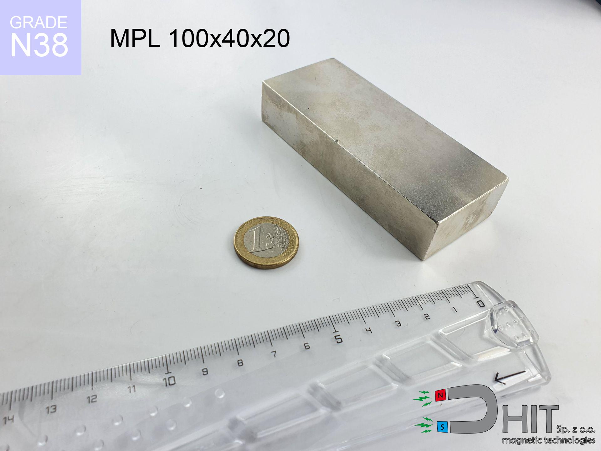
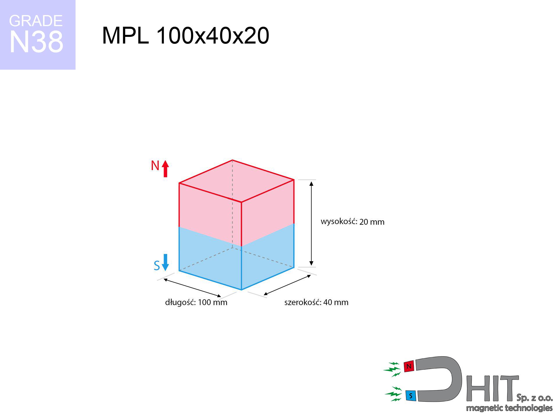

MPL 100x40x20 / N38 - lamellar magnet
lamellar magnet
Catalog no 020109
GTIN/EAN: 5906301811152
- length
- 100 mm [±0,1 mm]
- Width
- 40 mm [±0,1 mm]
- Height
- 20 mm [±0,1 mm]
- Weight
- 600 g
- Magnetization Direction
- ↑ axial
- Coating
- [NiCuNi] Nickel
How we measure these parameters — certificates and measurements
272.60 zł net / pcs
335.30 zł with VAT (23% VAT) / pcs
bulk discounts:
Need more?Frequently asked questions
What pull rating should I choose for a workshop block magnet?
Are block neodymium magnets available in more durable versions?
How should I choose block magnets for mounting a structure?
Engineering report for this magnet
Full PDF analysis: pull and shear force, effect of distance, temperature and plate thickness, safety distances and the demagnetization curve.
Call us now
+48 888 99 98 98
alternatively let us know using
contact form
the contact section.
Specifications and structure of a neodymium magnet can be estimated using our
power calculator.
Order by 14:00 and we’ll ship today!
Technical of the product - MPL 100x40x20 / N38 - lamellar magnet
Specification / characteristics - MPL 100x40x20 / N38 - lamellar magnet
| properties | values |
|---|---|
| Cat. no. | 020109 |
| GTIN/EAN | 5906301811152 |
| Production/Distribution | Dhit sp. z o.o. |
| Country of origin | Poland / China / Germany |
| Customs code | 85059029 |
| length | 100 mm [±0,1 mm] |
| Width | 40 mm [±0,1 mm] |
| Height | 20 mm [±0,1 mm] |
| Weight | 600 g |
| Magnetization Direction | ↑ axial |
| Load capacity ~ ? | 120.01 kg / 1177.33 N |
| Magnetic Induction ~ ? | 337.24 mT / 3372 Gs |
| Coating | [NiCuNi] Nickel |
| Manufacturing Tolerance | ±0.1 mm |
Magnetic properties of material N38
| properties | values | units |
|---|---|---|
| Remanence Br ? | 12.2-12.6 | kGs |
| Remanence Br ? | 1220-1260 | mT |
| Coercivity bHc ? | 10.8-11.5 | kOe |
| Coercivity bHc ? | 860-915 | kA/m |
| Intrinsic coercivity iHc | ≥ 12 | kOe |
| Intrinsic coercivity iHc | ≥ 955 | kA/m |
| Energy product BHmax ? | 36-38 | BH max MGOe |
| Energy product BHmax ? | 287-303 | BH max KJ/m |
| Maximum working temperature ? | ≤ 80 | °C |
Physical properties of sintered neodymium magnets Nd2Fe14B at 20°C
| properties | values | units |
|---|---|---|
| Vickers hardness | ≥550 | Hv |
| Density | ≥7.4 | g/cm3 |
| Curie Temperature TC | 310 | °C |
| Curie Temperature TF | 590 | °F |
| Specific resistance | 150 | μΩ⋅cm |
| Bending strength | 250 | MPa |
| Compressive strength | 1000~1100 | MPa |
| Thermal expansion parallel (∥) to orientation (M) | (3-4) x 10-6 | °C-1 |
| Thermal expansion perpendicular (⊥) to orientation (M) | -(1-3) x 10-6 | °C-1 |
| Young's modulus | 1.7 x 10⁴ | kg/mm² |
Technical simulation of the assembly - report
Presented data constitute the direct effect of a engineering calculation. Values rely on algorithms for the class Nd2Fe14B. Actual performance may deviate from the simulation results. Use these calculations as a preliminary roadmap when designing systems.
Table 1: Static pull force (force vs gap) - power drop
MPL 100x40x20 / N38
| Distance (mm) | Induction (Gauss) / mT | Pull Force (kg/lbs/g/N) | Risk Status |
|---|---|---|---|
| 0 mm |
3372 Gs
337.2 mT
|
120.01 kg / 264.58 LBS
120010.0 g / 1177.3 N
|
dangerous! |
| 1 mm |
3268 Gs
326.8 mT
|
112.70 kg / 248.45 LBS
112695.4 g / 1105.5 N
|
dangerous! |
| 2 mm |
3158 Gs
315.8 mT
|
105.27 kg / 232.09 LBS
105272.6 g / 1032.7 N
|
dangerous! |
| 3 mm |
3046 Gs
304.6 mT
|
97.92 kg / 215.88 LBS
97921.3 g / 960.6 N
|
dangerous! |
| 5 mm |
2818 Gs
281.8 mT
|
83.78 kg / 184.71 LBS
83783.3 g / 821.9 N
|
dangerous! |
| 10 mm |
2266 Gs
226.6 mT
|
54.17 kg / 119.43 LBS
54174.5 g / 531.5 N
|
dangerous! |
| 15 mm |
1794 Gs
179.4 mT
|
33.96 kg / 74.86 LBS
33955.7 g / 333.1 N
|
dangerous! |
| 20 mm |
1419 Gs
141.9 mT
|
21.25 kg / 46.84 LBS
21248.1 g / 208.4 N
|
dangerous! |
| 30 mm |
908 Gs
90.8 mT
|
8.70 kg / 19.17 LBS
8696.3 g / 85.3 N
|
strong |
| 50 mm |
416 Gs
41.6 mT
|
1.83 kg / 4.02 LBS
1825.4 g / 17.9 N
|
safe |
Table 2: Shear capacity (vertical surface)
MPL 100x40x20 / N38
| Distance (mm) | Friction coefficient | Pull Force (kg/lbs/g/N) |
|---|---|---|
| 0 mm | Stal (~0.2) |
24.00 kg / 52.92 LBS
24002.0 g / 235.5 N
|
| 1 mm | Stal (~0.2) |
22.54 kg / 49.69 LBS
22540.0 g / 221.1 N
|
| 2 mm | Stal (~0.2) |
21.05 kg / 46.42 LBS
21054.0 g / 206.5 N
|
| 3 mm | Stal (~0.2) |
19.58 kg / 43.18 LBS
19584.0 g / 192.1 N
|
| 5 mm | Stal (~0.2) |
16.76 kg / 36.94 LBS
16756.0 g / 164.4 N
|
| 10 mm | Stal (~0.2) |
10.83 kg / 23.88 LBS
10834.0 g / 106.3 N
|
| 15 mm | Stal (~0.2) |
6.79 kg / 14.97 LBS
6792.0 g / 66.6 N
|
| 20 mm | Stal (~0.2) |
4.25 kg / 9.37 LBS
4250.0 g / 41.7 N
|
| 30 mm | Stal (~0.2) |
1.74 kg / 3.84 LBS
1740.0 g / 17.1 N
|
| 50 mm | Stal (~0.2) |
0.37 kg / 0.81 LBS
366.0 g / 3.6 N
|
Table 3: Wall mounting (shearing) - vertical pull
MPL 100x40x20 / N38
| Surface type | Friction coefficient / % Mocy | Max load (kg/lbs/g/N) |
|---|---|---|
| Raw steel |
µ = 0.3
30% Nominalnej Siły
|
36.00 kg / 79.37 LBS
36003.0 g / 353.2 N
|
| Painted steel (standard) |
µ = 0.2
20% Nominalnej Siły
|
24.00 kg / 52.92 LBS
24002.0 g / 235.5 N
|
| Oily/slippery steel |
µ = 0.1
10% Nominalnej Siły
|
12.00 kg / 26.46 LBS
12001.0 g / 117.7 N
|
| Magnet with anti-slip rubber |
µ = 0.5
50% Nominalnej Siły
|
60.01 kg / 132.29 LBS
60005.0 g / 588.6 N
|
Table 4: Steel thickness (substrate influence) - sheet metal selection
MPL 100x40x20 / N38
| Steel thickness (mm) | % power | Real pull force (kg/lbs/g/N) |
|---|---|---|
| 0.5 mm |
|
4.00 kg / 8.82 LBS
4000.3 g / 39.2 N
|
| 1 mm |
|
10.00 kg / 22.05 LBS
10000.8 g / 98.1 N
|
| 2 mm |
|
20.00 kg / 44.10 LBS
20001.7 g / 196.2 N
|
| 3 mm |
|
30.00 kg / 66.14 LBS
30002.5 g / 294.3 N
|
| 5 mm |
|
50.00 kg / 110.24 LBS
50004.2 g / 490.5 N
|
| 10 mm |
|
100.01 kg / 220.48 LBS
100008.3 g / 981.1 N
|
| 11 mm |
|
110.01 kg / 242.53 LBS
110009.2 g / 1079.2 N
|
| 12 mm |
|
120.01 kg / 264.58 LBS
120010.0 g / 1177.3 N
|
Table 5: Thermal resistance (material behavior) - power drop
MPL 100x40x20 / N38
| Ambient temp. (°C) | Power loss | Remaining pull (kg/lbs/g/N) | Status |
|---|---|---|---|
| 20 °C | 0.0% |
120.01 kg / 264.58 LBS
120010.0 g / 1177.3 N
|
OK |
| 40 °C | -2.2% |
117.37 kg / 258.76 LBS
117369.8 g / 1151.4 N
|
OK |
| 60 °C | -4.4% |
114.73 kg / 252.94 LBS
114729.6 g / 1125.5 N
|
|
| 80 °C | -6.6% |
112.09 kg / 247.11 LBS
112089.3 g / 1099.6 N
|
|
| 100 °C | -28.8% |
85.45 kg / 188.38 LBS
85447.1 g / 838.2 N
|
Table 6: Two magnets (repulsion) - forces in the system
MPL 100x40x20 / N38
| Gap (mm) | Attraction (kg/lbs) (N-S) | Sliding Force (kg/lbs/g/N) | Repulsion (kg/lbs) (N-N) |
|---|---|---|---|
| 0 mm |
280.40 kg / 618.18 LBS
4 790 Gs
|
42.06 kg / 92.73 LBS
42060 g / 412.6 N
|
N/A |
| 1 mm |
271.97 kg / 599.59 LBS
6 642 Gs
|
40.80 kg / 89.94 LBS
40796 g / 400.2 N
|
244.77 kg / 539.63 LBS
~0 Gs
|
| 2 mm |
263.31 kg / 580.50 LBS
6 535 Gs
|
39.50 kg / 87.08 LBS
39497 g / 387.5 N
|
236.98 kg / 522.45 LBS
~0 Gs
|
| 3 mm |
254.63 kg / 561.37 LBS
6 427 Gs
|
38.20 kg / 84.21 LBS
38195 g / 374.7 N
|
229.17 kg / 505.24 LBS
~0 Gs
|
| 5 mm |
237.35 kg / 523.26 LBS
6 205 Gs
|
35.60 kg / 78.49 LBS
35602 g / 349.3 N
|
213.61 kg / 470.93 LBS
~0 Gs
|
| 10 mm |
195.76 kg / 431.58 LBS
5 635 Gs
|
29.36 kg / 64.74 LBS
29364 g / 288.1 N
|
176.18 kg / 388.42 LBS
~0 Gs
|
| 20 mm |
126.58 kg / 279.06 LBS
4 531 Gs
|
18.99 kg / 41.86 LBS
18987 g / 186.3 N
|
113.92 kg / 251.15 LBS
~0 Gs
|
| 50 mm |
31.47 kg / 69.38 LBS
2 259 Gs
|
4.72 kg / 10.41 LBS
4721 g / 46.3 N
|
28.32 kg / 62.44 LBS
~0 Gs
|
| 60 mm |
20.32 kg / 44.80 LBS
1 815 Gs
|
3.05 kg / 6.72 LBS
3048 g / 29.9 N
|
18.29 kg / 40.32 LBS
~0 Gs
|
| 70 mm |
13.38 kg / 29.50 LBS
1 473 Gs
|
2.01 kg / 4.42 LBS
2007 g / 19.7 N
|
12.04 kg / 26.55 LBS
~0 Gs
|
| 80 mm |
8.98 kg / 19.80 LBS
1 207 Gs
|
1.35 kg / 2.97 LBS
1347 g / 13.2 N
|
8.08 kg / 17.82 LBS
~0 Gs
|
| 90 mm |
6.14 kg / 13.53 LBS
998 Gs
|
0.92 kg / 2.03 LBS
920 g / 9.0 N
|
5.52 kg / 12.18 LBS
~0 Gs
|
| 100 mm |
4.27 kg / 9.40 LBS
832 Gs
|
0.64 kg / 1.41 LBS
640 g / 6.3 N
|
3.84 kg / 8.46 LBS
~0 Gs
|
Table 7: Protective zones (implants) - warnings
MPL 100x40x20 / N38
| Object / Device | Limit (Gauss) / mT | Safe distance |
|---|---|---|
| Pacemaker | 5 Gs (0.5 mT) | 30.5 cm |
| Hearing aid | 10 Gs (1.0 mT) | 24.0 cm |
| Mechanical watch | 20 Gs (2.0 mT) | 18.5 cm |
| Phone / Smartphone | 40 Gs (4.0 mT) | 14.5 cm |
| Remote | 50 Gs (5.0 mT) | 13.5 cm |
| Payment card | 400 Gs (40.0 mT) | 5.5 cm |
| HDD hard drive | 600 Gs (60.0 mT) | 4.5 cm |
Table 8: Collisions (cracking risk) - warning
MPL 100x40x20 / N38
| Start from (mm) | Speed (km/h) | Energy (J) | Predicted outcome |
|---|---|---|---|
| 10 mm |
18.98 km/h
(5.27 m/s)
|
8.34 J | |
| 30 mm |
23.84 km/h
(6.62 m/s)
|
13.16 J | |
| 50 mm |
24.60 km/h
(6.83 m/s)
|
14.00 J | |
| 100 mm |
24.83 km/h
(6.90 m/s)
|
14.27 J |
Table 9: Surface protection spec
MPL 100x40x20 / N38
| Technical parameter | Value / Description |
|---|---|
| Coating type | [NiCuNi] Nickel |
| Layer structure | Nickel - Copper - Nickel |
| Layer thickness | 10-20 µm |
| Salt spray test (SST) ? | 24 h |
| Recommended environment | Indoors only (dry) |
Table 10: Construction data (Flux)
MPL 100x40x20 / N38
| Parameter | Value | SI Unit / Description |
|---|---|---|
| Magnetic Flux | 131 922 Mx | 1319.2 µWb |
| Pc Coefficient | 0.38 | Low (Flat) |
Table 11: Submerged application
MPL 100x40x20 / N38
| Environment | Effective steel pull | Effect |
|---|---|---|
| Air (land) | 120.01 kg | Standard |
| Water (riverbed) |
137.41 kg
(+17.40 kg buoyancy gain)
|
+14.5% |
1. Wall mount (shear)
*Note: On a vertical wall, the magnet retains only a fraction of its perpendicular strength.
2. Plate thickness effect
*Thin metal sheet (e.g. computer case) drastically limits the holding force.
3. Thermal stability
N38: the maximum material working temperature is 80°C. Permitted conditions also depend on the shape and magnetic circuit.
4. Demagnetization curve and operating point (B-H)
chart generated for the permeance coefficient Pc (Permeance Coefficient) = 0.38
This simulation demonstrates the magnetic stability of the selected magnet under specific geometric conditions. The solid red line represents the demagnetization curve (material potential), while the dashed blue line is the load line based on the magnet's geometry. The Pc (Permeance Coefficient), also known as the load line slope, is a dimensionless value that describes the relationship between the magnet's shape and its magnetic stability. The intersection of these two lines (the black dot) is the operating point — it determines the actual magnetic flux density generated by the magnet in this specific configuration. A higher Pc value means the magnet is more 'slender' (tall relative to its area), resulting in a higher operating point and better resistance to irreversible demagnetization caused by external fields or temperature. A value of 0.42 is relatively low (typical for flat magnets), meaning the operating point is closer to the 'knee' of the curve — caution is advised when operating at temperatures near the maximum limit to avoid strength loss.
Chemical composition
| iron (Fe) | 64% – 68% |
| neodymium (Nd) | 29% – 32% |
| boron (B) | 1.1% – 1.2% |
| dysprosium (Dy) | 0.5% – 2.0% |
| coating (Ni-Cu-Ni) | < 0.05% |
Ecology and recycling (GPSR)
| recyclability (EoL) | 100% |
| recycled raw materials | ~10% (pre-cons) |
| carbon footprint | low / zredukowany |
| waste code (EWC) | 16 02 16 |
View also offers
![BM 750x180x70 [4x M8] - magnetic beam](https://cdn3.dhit.pl/graphics/products/bm-750x180x70-4x-m8-zif.jpg "BM 750x180x70 [4x M8] - magnetic beam")
![SM 32x225 [2xM8] / N42 - magnetic separator](https://cdn3.dhit.pl/graphics/products/sm-32x225-2xm8-dob.jpg "SM 32x225 [2xM8] / N42 - magnetic separator")

Pros and cons of Nd2Fe14B magnets.
Pros
- They have stable power, and over more than 10 years their performance decreases symbolically – ~1% (according to theory),
- Neodymium magnets are exceptionally resistant to loss of magnetic properties caused by external interference,
- By using a smooth coating of gold, the element gains an professional look,
- Magnets are characterized by exceptionally strong magnetic induction on the outer side,
- Neodymium magnets are characterized by very high magnetic induction on the magnet surface and are able to act (depending on the shape) even at a temperature of 230°C or more...
- Possibility of accurate machining as well as optimizing to specific applications,
- Universal use in innovative solutions – they find application in data components, motor assemblies, medical devices, also complex engineering applications.
- Thanks to efficiency per cm³, small magnets offer high operating force, with minimal size,
Limitations
- They are fragile upon too strong impacts. To avoid cracks, it is worth securing magnets using a steel holder. Such protection not only shields the magnet but also increases its resistance to damage
- Do not exceed this material temperature limit: 80°C. Overheating may permanently weaken the magnet.
- Due to the susceptibility of magnets to corrosion in a humid environment, we suggest using waterproof magnets made of rubber, plastic or other material stable to moisture, in case of application outdoors
- We suggest casing - magnetic holder, due to difficulties in realizing threads inside the magnet and complex shapes.
- Possible danger resulting from small fragments of magnets can be dangerous, in case of ingestion, which gains importance in the context of child safety. It is also worth noting that small components of these products are able to complicate diagnosis medical when they are in the body.
- High unit price – neodymium magnets cost more than other types of magnets (e.g. ferrite), which hinders application in large quantities
Pull force analysis
Optimal lifting capacity of a neodymium magnet – what it depends on?
- on a base made of mild steel, perfectly concentrating the magnetic field
- possessing a thickness of min. 10 mm to ensure full flux closure
- characterized by smoothness
- under conditions of ideal adhesion (metal-to-metal)
- under vertical force vector (90-degree angle)
- at temperature approx. 20 degrees Celsius
Key elements affecting lifting force
- Clearance – existence of any layer (rust, dirt, air) interrupts the magnetic circuit, which reduces capacity steeply (even by 50% at 0.5 mm).
- Force direction – declared lifting capacity refers to pulling vertically. When applying parallel force, the magnet holds significantly lower power (often approx. 20-30% of maximum force).
- Plate thickness – insufficiently thick plate does not close the flux, causing part of the power to be lost to the other side.
- Metal type – not every steel attracts identically. High carbon content weaken the attraction effect.
- Surface condition – ground elements guarantee perfect abutment, which improves force. Uneven metal weaken the grip.
- Thermal factor – hot environment weakens magnetic field. Too high temperature can permanently demagnetize the magnet.
Lifting capacity testing was carried out on a smooth plate of optimal thickness, under perpendicular forces, in contrast under attempts to slide the magnet the load capacity is reduced by as much as 75%. In addition, even a minimal clearance between the magnet’s surface and the plate decreases the lifting capacity.
Precautions when working with NdFeB magnets
Keep away from children
Neodymium magnets are not intended for children. Swallowing multiple magnets can lead to them connecting inside the digestive tract, which poses a critical condition and requires immediate surgery.
Immense force
Before use, check safety instructions. Sudden snapping can destroy the magnet or injure your hand. Be predictive.
Crushing force
Risk of injury: The pulling power is so immense that it can cause hematomas, pinching, and broken bones. Protective gloves are recommended.
GPS and phone interference
Remember: rare earth magnets produce a field that disrupts sensitive sensors. Maintain a safe distance from your phone, tablet, and navigation systems.
Warning for allergy sufferers
Nickel alert: The Ni-Cu-Ni coating consists of nickel. If an allergic reaction happens, cease handling magnets and use protective gear.
Thermal limits
Avoid heat. NdFeB magnets are susceptible to temperature. If you need resistance above 80°C, ask us about special high-temperature series (H, SH, UH).
Do not drill into magnets
Combustion risk: Rare earth powder is highly flammable. Do not process magnets without safety gear as this may cause fire.
Data carriers
Equipment safety: Strong magnets can damage data carriers and sensitive devices (heart implants, hearing aids, timepieces).
Fragile material
Watch out for shards. Magnets can fracture upon violent connection, ejecting shards into the air. Eye protection is mandatory.
Life threat
Warning for patients: Powerful magnets disrupt electronics. Keep at least 30 cm distance or request help to work with the magnets.
Tabela kosztu i czasu dostawy
Płatność przed wysyłką:

GLS kurier
Przesyłka będzie u Ciebie za 2-3 dni
14.99 ZŁ

InPost Paczkomaty 24/7
Przesyłka będzie u Ciebie za 1-2 dni
12.30 ZŁ
Płatność przy odbiorze (pobranie):
GLS kurier
Przesyłka będzie u Ciebie za 1-2 dni
23.00 ZŁ