

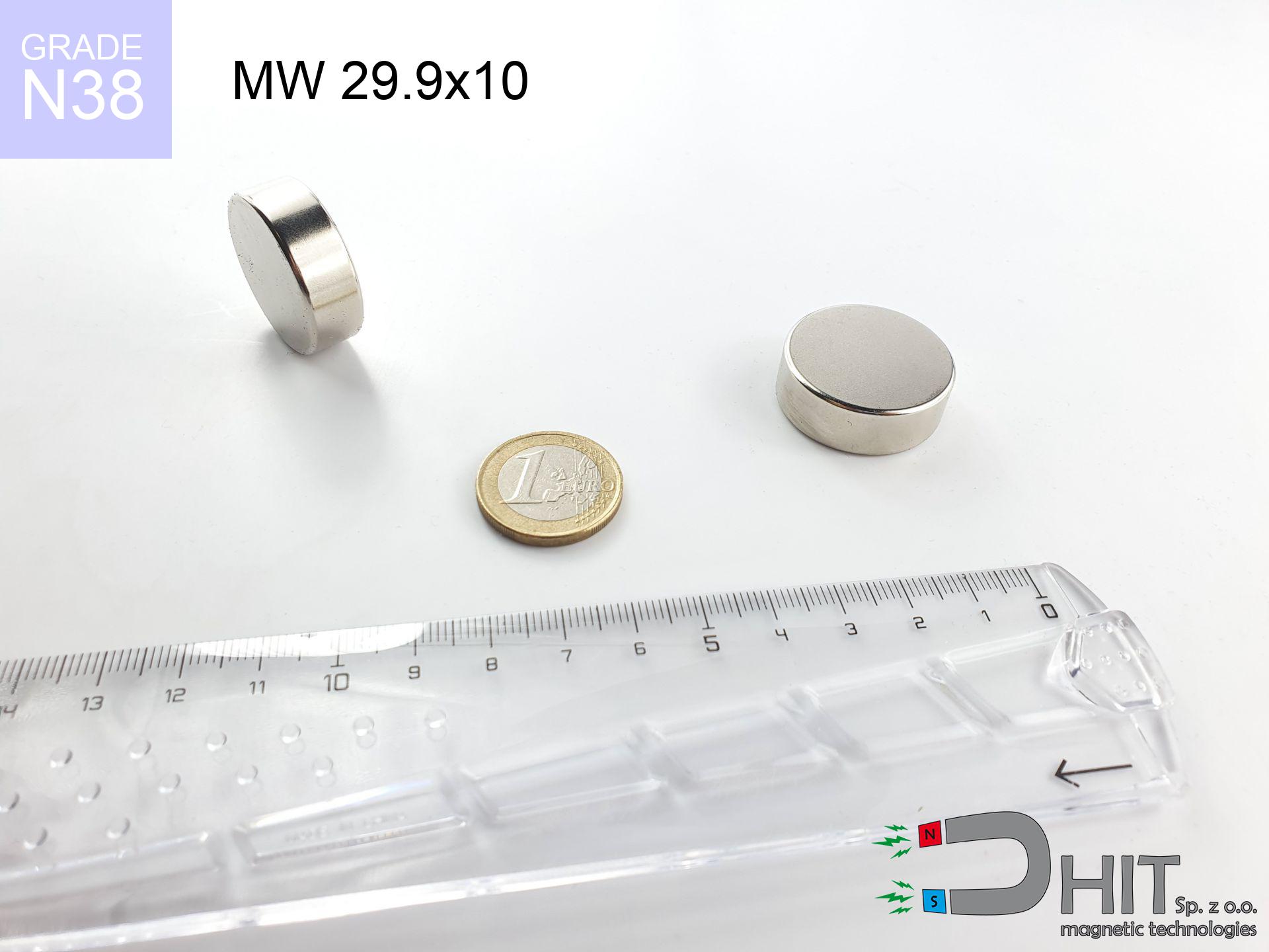
MW 29.9x10 / N38 - cylindrical magnet
cylindrical magnet
Catalog no 010052
GTIN/EAN: 5906301810513
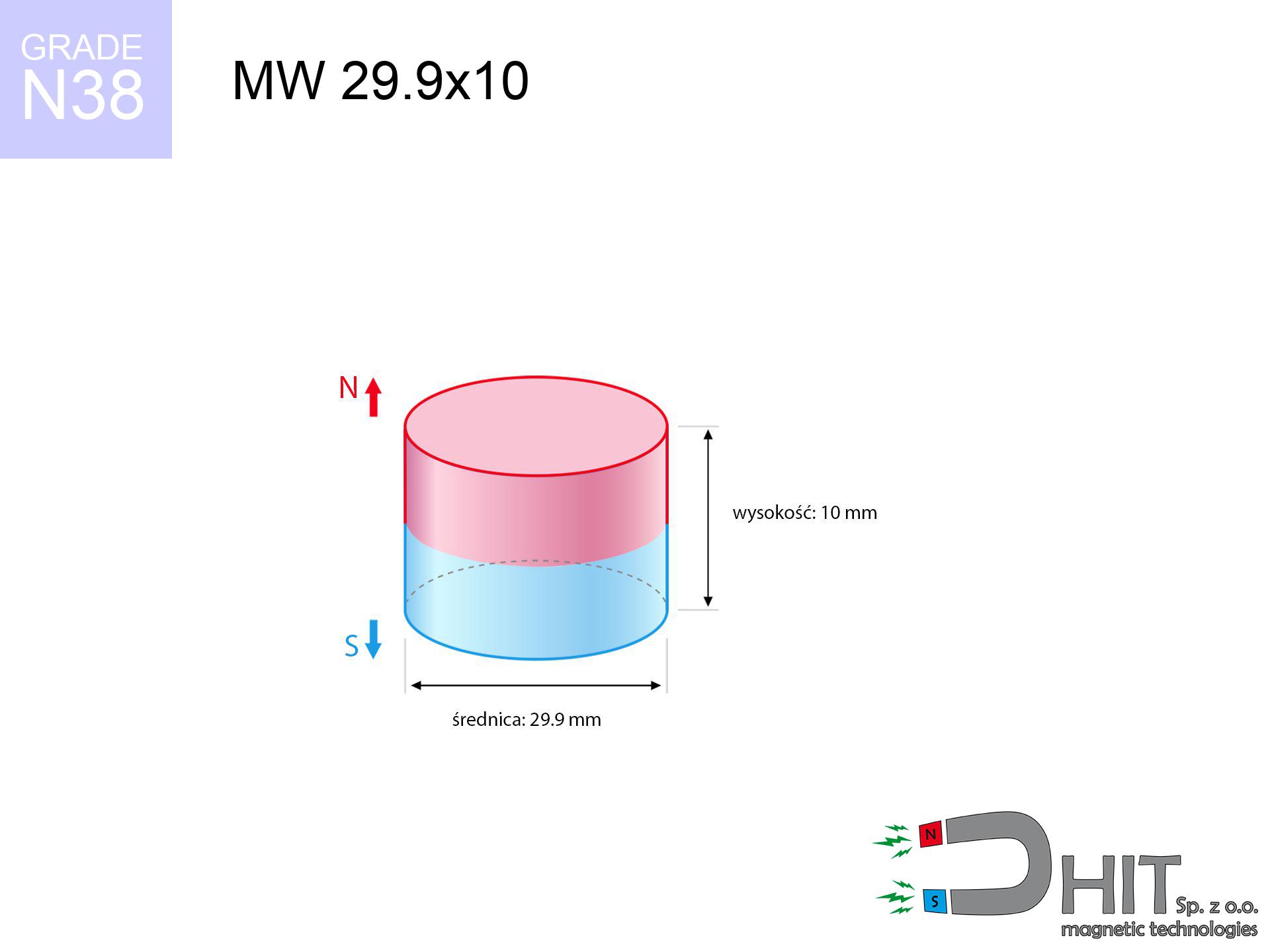
- Diameter Ø
- 29.9 mm [±0,1 mm]
- Height
- 10 mm [±0,1 mm]
- Weight
- 52.66 g
- Magnetization Direction
- → diametrical
- Coating
- [NiCuNi] Nickel
How we measure these parameters — certificates and measurements
20.00 zł net / pcs
24.60 zł with VAT (23% VAT) / pcs
bulk discounts:
Need more?Frequently asked questions
Where can I buy strong cylindrical neodymium magnets?
Can a small cylindrical magnet provide a strong grip for precise workshop work?
Which cylindrical magnet can work at a higher temperature?
Call us now
+48 888 99 98 98
alternatively let us know using
contact form
the contact section.
Specifications and structure of a neodymium magnet can be estimated using our
power calculator.
Order by 14:00 and we’ll ship today!
Technical specification of the product - MW 29.9x10 / N38 - cylindrical magnet
Specification / characteristics - MW 29.9x10 / N38 - cylindrical magnet
| properties | values |
|---|---|
| Cat. no. | 010052 |
| GTIN/EAN | 5906301810513 |
| Production/Distribution | Dhit sp. z o.o. |
| Country of origin | Poland / China / Germany |
| Customs code | 85059029 |
| Diameter Ø | 29.9 mm [±0,1 mm] |
| Height | 10 mm [±0,1 mm] |
| Weight | 52.66 g |
| Magnetization Direction | → diametrical |
| Load capacity ~ ? | 21.50 kg / 210.90 N |
| Magnetic Induction ~ ? | 344.60 mT / 3446 Gs |
| Coating | [NiCuNi] Nickel |
| Manufacturing Tolerance | ±0.1 mm |
Magnetic properties of material N38
| properties | values | units |
|---|---|---|
| Remanence Br ? | 12.2-12.6 | kGs |
| Remanence Br ? | 1220-1260 | mT |
| Coercivity bHc ? | 10.8-11.5 | kOe |
| Coercivity bHc ? | 860-915 | kA/m |
| Intrinsic coercivity iHc | ≥ 12 | kOe |
| Intrinsic coercivity iHc | ≥ 955 | kA/m |
| Energy product BHmax ? | 36-38 | BH max MGOe |
| Energy product BHmax ? | 287-303 | BH max KJ/m |
| Maximum working temperature ? | ≤ 80 | °C |
Physical properties of sintered neodymium magnets Nd2Fe14B at 20°C
| properties | values | units |
|---|---|---|
| Vickers hardness | ≥550 | Hv |
| Density | ≥7.4 | g/cm3 |
| Curie Temperature TC | 310 | °C |
| Curie Temperature TF | 590 | °F |
| Specific resistance | 150 | μΩ⋅cm |
| Bending strength | 250 | MPa |
| Compressive strength | 1000~1100 | MPa |
| Thermal expansion parallel (∥) to orientation (M) | (3-4) x 10-6 | °C-1 |
| Thermal expansion perpendicular (⊥) to orientation (M) | -(1-3) x 10-6 | °C-1 |
| Young's modulus | 1.7 x 10⁴ | kg/mm² |
Technical modeling of the product - technical parameters
Presented data represent the outcome of a physical analysis. Values are based on algorithms for the material Nd2Fe14B. Actual conditions might slightly differ. Use these calculations as a reference point during assembly planning.
Table 1: Static pull force (force vs gap) - interaction chart
MW 29.9x10 / N38
| Distance (mm) | Induction (Gauss) / mT | Pull Force (kg/lbs/g/N) | Risk Status |
|---|---|---|---|
| 0 mm |
3445 Gs
344.5 mT
|
21.50 kg / 47.40 lbs
21500.0 g / 210.9 N
|
crushing |
| 1 mm |
3261 Gs
326.1 mT
|
19.26 kg / 42.45 lbs
19256.6 g / 188.9 N
|
crushing |
| 2 mm |
3059 Gs
305.9 mT
|
16.95 kg / 37.36 lbs
16947.4 g / 166.3 N
|
crushing |
| 3 mm |
2848 Gs
284.8 mT
|
14.70 kg / 32.40 lbs
14696.2 g / 144.2 N
|
crushing |
| 5 mm |
2425 Gs
242.5 mT
|
10.65 kg / 23.48 lbs
10650.1 g / 104.5 N
|
crushing |
| 10 mm |
1519 Gs
151.9 mT
|
4.18 kg / 9.21 lbs
4178.4 g / 41.0 N
|
strong |
| 15 mm |
930 Gs
93.0 mT
|
1.57 kg / 3.45 lbs
1565.8 g / 15.4 N
|
weak grip |
| 20 mm |
583 Gs
58.3 mT
|
0.62 kg / 1.36 lbs
616.0 g / 6.0 N
|
weak grip |
| 30 mm |
258 Gs
25.8 mT
|
0.12 kg / 0.27 lbs
121.0 g / 1.2 N
|
weak grip |
| 50 mm |
76 Gs
7.6 mT
|
0.01 kg / 0.02 lbs
10.4 g / 0.1 N
|
weak grip |
Table 2: Shear hold (wall)
MW 29.9x10 / N38
| Distance (mm) | Friction coefficient | Pull Force (kg/lbs/g/N) |
|---|---|---|
| 0 mm | Stal (~0.2) |
4.30 kg / 9.48 lbs
4300.0 g / 42.2 N
|
| 1 mm | Stal (~0.2) |
3.85 kg / 8.49 lbs
3852.0 g / 37.8 N
|
| 2 mm | Stal (~0.2) |
3.39 kg / 7.47 lbs
3390.0 g / 33.3 N
|
| 3 mm | Stal (~0.2) |
2.94 kg / 6.48 lbs
2940.0 g / 28.8 N
|
| 5 mm | Stal (~0.2) |
2.13 kg / 4.70 lbs
2130.0 g / 20.9 N
|
| 10 mm | Stal (~0.2) |
0.84 kg / 1.84 lbs
836.0 g / 8.2 N
|
| 15 mm | Stal (~0.2) |
0.31 kg / 0.69 lbs
314.0 g / 3.1 N
|
| 20 mm | Stal (~0.2) |
0.12 kg / 0.27 lbs
124.0 g / 1.2 N
|
| 30 mm | Stal (~0.2) |
0.02 kg / 0.05 lbs
24.0 g / 0.2 N
|
| 50 mm | Stal (~0.2) |
0.00 kg / 0.00 lbs
2.0 g / 0.0 N
|
Table 3: Wall mounting (shearing) - behavior on slippery surfaces
MW 29.9x10 / N38
| Surface type | Friction coefficient / % Mocy | Max load (kg/lbs/g/N) |
|---|---|---|
| Raw steel |
µ = 0.3
30% Nominalnej Siły
|
6.45 kg / 14.22 lbs
6450.0 g / 63.3 N
|
| Painted steel (standard) |
µ = 0.2
20% Nominalnej Siły
|
4.30 kg / 9.48 lbs
4300.0 g / 42.2 N
|
| Oily/slippery steel |
µ = 0.1
10% Nominalnej Siły
|
2.15 kg / 4.74 lbs
2150.0 g / 21.1 N
|
| Magnet with anti-slip rubber |
µ = 0.5
50% Nominalnej Siły
|
10.75 kg / 23.70 lbs
10750.0 g / 105.5 N
|
Table 4: Steel thickness (saturation) - power losses
MW 29.9x10 / N38
| Steel thickness (mm) | % power | Real pull force (kg/lbs/g/N) |
|---|---|---|
| 0.5 mm |
|
1.08 kg / 2.37 lbs
1075.0 g / 10.5 N
|
| 1 mm |
|
2.69 kg / 5.92 lbs
2687.5 g / 26.4 N
|
| 2 mm |
|
5.38 kg / 11.85 lbs
5375.0 g / 52.7 N
|
| 3 mm |
|
8.06 kg / 17.77 lbs
8062.5 g / 79.1 N
|
| 5 mm |
|
13.44 kg / 29.62 lbs
13437.5 g / 131.8 N
|
| 10 mm |
|
21.50 kg / 47.40 lbs
21500.0 g / 210.9 N
|
| 11 mm |
|
21.50 kg / 47.40 lbs
21500.0 g / 210.9 N
|
| 12 mm |
|
21.50 kg / 47.40 lbs
21500.0 g / 210.9 N
|
Table 5: Thermal stability (material behavior) - resistance threshold
MW 29.9x10 / N38
| Ambient temp. (°C) | Power loss | Remaining pull (kg/lbs/g/N) | Status |
|---|---|---|---|
| 20 °C | 0.0% |
21.50 kg / 47.40 lbs
21500.0 g / 210.9 N
|
OK |
| 40 °C | -2.2% |
21.03 kg / 46.36 lbs
21027.0 g / 206.3 N
|
OK |
| 60 °C | -4.4% |
20.55 kg / 45.31 lbs
20554.0 g / 201.6 N
|
|
| 80 °C | -6.6% |
20.08 kg / 44.27 lbs
20081.0 g / 197.0 N
|
|
| 100 °C | -28.8% |
15.31 kg / 33.75 lbs
15308.0 g / 150.2 N
|
Table 6: Magnet-Magnet interaction (attraction) - field range
MW 29.9x10 / N38
| Gap (mm) | Attraction (kg/lbs) (N-S) | Shear Strength (kg/lbs/g/N) | Repulsion (kg/lbs) (N-N) |
|---|---|---|---|
| 0 mm |
51.38 kg / 113.28 lbs
4 963 Gs
|
7.71 kg / 16.99 lbs
7708 g / 75.6 N
|
N/A |
| 1 mm |
48.76 kg / 107.50 lbs
6 712 Gs
|
7.31 kg / 16.12 lbs
7314 g / 71.7 N
|
43.88 kg / 96.75 lbs
~0 Gs
|
| 2 mm |
46.02 kg / 101.46 lbs
6 521 Gs
|
6.90 kg / 15.22 lbs
6903 g / 67.7 N
|
41.42 kg / 91.32 lbs
~0 Gs
|
| 3 mm |
43.26 kg / 95.37 lbs
6 322 Gs
|
6.49 kg / 14.31 lbs
6489 g / 63.7 N
|
38.93 kg / 85.83 lbs
~0 Gs
|
| 5 mm |
37.78 kg / 83.30 lbs
5 909 Gs
|
5.67 kg / 12.49 lbs
5667 g / 55.6 N
|
34.00 kg / 74.97 lbs
~0 Gs
|
| 10 mm |
25.45 kg / 56.11 lbs
4 850 Gs
|
3.82 kg / 8.42 lbs
3818 g / 37.5 N
|
22.91 kg / 50.50 lbs
~0 Gs
|
| 20 mm |
9.99 kg / 22.02 lbs
3 038 Gs
|
1.50 kg / 3.30 lbs
1498 g / 14.7 N
|
8.99 kg / 19.81 lbs
~0 Gs
|
| 50 mm |
0.63 kg / 1.38 lbs
761 Gs
|
0.09 kg / 0.21 lbs
94 g / 0.9 N
|
0.56 kg / 1.24 lbs
~0 Gs
|
| 60 mm |
0.29 kg / 0.64 lbs
517 Gs
|
0.04 kg / 0.10 lbs
43 g / 0.4 N
|
0.26 kg / 0.57 lbs
~0 Gs
|
| 70 mm |
0.14 kg / 0.32 lbs
364 Gs
|
0.02 kg / 0.05 lbs
22 g / 0.2 N
|
0.13 kg / 0.28 lbs
~0 Gs
|
| 80 mm |
0.08 kg / 0.17 lbs
265 Gs
|
0.01 kg / 0.03 lbs
11 g / 0.1 N
|
0.07 kg / 0.15 lbs
~0 Gs
|
| 90 mm |
0.04 kg / 0.09 lbs
198 Gs
|
0.01 kg / 0.01 lbs
6 g / 0.1 N
|
0.04 kg / 0.08 lbs
~0 Gs
|
| 100 mm |
0.02 kg / 0.05 lbs
152 Gs
|
0.00 kg / 0.01 lbs
4 g / 0.0 N
|
0.02 kg / 0.05 lbs
~0 Gs
|
Table 7: Protective zones (implants) - warnings
MW 29.9x10 / N38
| Object / Device | Limit (Gauss) / mT | Safe distance |
|---|---|---|
| Pacemaker | 5 Gs (0.5 mT) | 13.5 cm |
| Hearing aid | 10 Gs (1.0 mT) | 11.0 cm |
| Mechanical watch | 20 Gs (2.0 mT) | 8.5 cm |
| Phone / Smartphone | 40 Gs (4.0 mT) | 6.5 cm |
| Remote | 50 Gs (5.0 mT) | 6.0 cm |
| Payment card | 400 Gs (40.0 mT) | 2.5 cm |
| HDD hard drive | 600 Gs (60.0 mT) | 2.0 cm |
Table 8: Collisions (cracking risk) - warning
MW 29.9x10 / N38
| Start from (mm) | Speed (km/h) | Energy (J) | Predicted outcome |
|---|---|---|---|
| 10 mm |
23.51 km/h
(6.53 m/s)
|
1.12 J | |
| 30 mm |
25.61 km/h
(7.11 m/s)
|
1.33 J | |
| 50 mm |
25.69 km/h
(7.14 m/s)
|
1.34 J | |
| 100 mm |
25.70 km/h
(7.14 m/s)
|
1.34 J |
Table 9: Surface protection spec
MW 29.9x10 / N38
| Technical parameter | Value / Description |
|---|---|
| Coating type | [NiCuNi] Nickel |
| Layer structure | Nickel - Copper - Nickel |
| Layer thickness | 10-20 µm |
| Salt spray test (SST) ? | 24 h |
| Recommended environment | Indoors only (dry) |
Table 10: Electrical data (Flux)
MW 29.9x10 / N38
| Parameter | Value | SI Unit / Description |
|---|---|---|
| Magnetic Flux | 25 588 Mx | 255.9 µWb |
| Pc Coefficient | 0.44 | Low (Flat) |
Table 11: Submerged application
MW 29.9x10 / N38
| Environment | Effective steel pull | Effect |
|---|---|---|
| Air (land) | 21.50 kg | Standard |
| Water (riverbed) |
24.62 kg
(+3.12 kg buoyancy gain)
|
+14.5% |
1. Shear force
*Note: On a vertical surface, the magnet retains just approx. 20-30% of its perpendicular strength.
2. Steel saturation
*Thin metal sheet (e.g. computer case) severely reduces the holding force.
3. Power loss vs temp
N38: the maximum material working temperature is 80°C. Permitted conditions also depend on the shape and magnetic circuit.
4. Demagnetization curve and operating point (B-H)
chart generated for the permeance coefficient Pc (Permeance Coefficient) = 0.44
This simulation demonstrates the magnetic stability of the selected magnet under specific geometric conditions. The solid red line represents the demagnetization curve (material potential), while the dashed blue line is the load line based on the magnet's geometry. The Pc (Permeance Coefficient), also known as the load line slope, is a dimensionless value that describes the relationship between the magnet's shape and its magnetic stability. The intersection of these two lines (the black dot) is the operating point — it determines the actual magnetic flux density generated by the magnet in this specific configuration. A higher Pc value means the magnet is more 'slender' (tall relative to its area), resulting in a higher operating point and better resistance to irreversible demagnetization caused by external fields or temperature. A value of 0.42 is relatively low (typical for flat magnets), meaning the operating point is closer to the 'knee' of the curve — caution is advised when operating at temperatures near the maximum limit to avoid strength loss.
Chemical composition
| iron (Fe) | 64% – 68% |
| neodymium (Nd) | 29% – 32% |
| boron (B) | 1.1% – 1.2% |
| dysprosium (Dy) | 0.5% – 2.0% |
| coating (Ni-Cu-Ni) | < 0.05% |
Sustainability
| recyclability (EoL) | 100% |
| recycled raw materials | ~10% (pre-cons) |
| carbon footprint | low / zredukowany |
| waste code (EWC) | 16 02 16 |
Other offers
![SM 32x150 [2xM8] / N42 - magnetic separator](https://cdn3.dhit.pl/graphics/products/sm-32x150-2xm8-xus.jpg "SM 32x150 [2xM8] / N42 - magnetic separator")
Strengths as well as weaknesses of Nd2Fe14B magnets.
Pros
- They virtually do not lose strength, because even after 10 years the decline in efficiency is only ~1% (based on calculations),
- Magnets very well protect themselves against loss of magnetization caused by foreign field sources,
- A magnet with a metallic gold surface has an effective appearance,
- The surface of neodymium magnets generates a maximum magnetic field – this is a key feature,
- Neodymium magnets are characterized by extremely high magnetic induction on the magnet surface and can function (depending on the form) even at a temperature of 230°C or more...
- Thanks to modularity in designing and the ability to adapt to client solutions,
- Huge importance in electronics industry – they are commonly used in mass storage devices, drive modules, diagnostic systems, and technologically advanced constructions.
- Relatively small size with high pulling force – neodymium magnets offer high power in tiny dimensions, which makes them useful in miniature devices
Cons
- At strong impacts they can break, therefore we advise placing them in strong housings. A metal housing provides additional protection against damage and increases the magnet's durability.
- Do not exceed this material temperature limit: 80°C. Overheating may permanently weaken the magnet.
- Magnets exposed to a humid environment can corrode. Therefore during using outdoors, we advise using waterproof magnets made of rubber, plastic or other material resistant to moisture
- Due to limitations in creating threads and complicated shapes in magnets, we recommend using a housing - magnetic holder.
- Health risk to health – tiny shards of magnets are risky, if swallowed, which is particularly important in the context of child safety. Furthermore, small elements of these products are able to complicate diagnosis medical after entering the body.
- Higher cost of purchase is a significant factor to consider compared to ceramic magnets, especially in budget applications
Pull force analysis
Highest magnetic holding force – what affects it?
- using a sheet made of low-carbon steel, functioning as a circuit closing element
- with a thickness minimum 10 mm
- with a plane cleaned and smooth
- under conditions of gap-free contact (metal-to-metal)
- for force acting at a right angle (in the magnet axis)
- at ambient temperature approx. 20 degrees Celsius
What influences lifting capacity in practice
- Space between surfaces – every millimeter of separation (caused e.g. by varnish or dirt) significantly weakens the magnet efficiency, often by half at just 0.5 mm.
- Loading method – catalog parameter refers to detachment vertically. When applying parallel force, the magnet holds much less (often approx. 20-30% of maximum force).
- Substrate thickness – to utilize 100% power, the steel must be sufficiently thick. Paper-thin metal restricts the lifting capacity (the magnet "punches through" it).
- Metal type – not every steel attracts identically. Alloy additives weaken the attraction effect.
- Smoothness – ideal contact is obtained only on polished steel. Any scratches and bumps create air cushions, weakening the magnet.
- Thermal factor – hot environment weakens magnetic field. Exceeding the limit temperature can permanently damage the magnet.
Lifting capacity was determined with the use of a steel plate with a smooth surface of suitable thickness (min. 20 mm), under vertically applied force, in contrast under parallel forces the load capacity is reduced by as much as 5 times. In addition, even a slight gap between the magnet’s surface and the plate reduces the lifting capacity.
Safe handling of NdFeB magnets
Material brittleness
NdFeB magnets are ceramic materials, meaning they are very brittle. Clashing of two magnets leads to them cracking into small pieces.
Do not overheat magnets
Standard neodymium magnets (grade N) lose magnetization when the temperature exceeds 80°C. Damage is permanent.
Allergic reactions
Allergy Notice: The nickel-copper-nickel coating consists of nickel. If skin irritation happens, cease handling magnets and use protective gear.
Protect data
Equipment safety: Strong magnets can damage data carriers and delicate electronics (heart implants, hearing aids, timepieces).
Compass and GPS
GPS units and smartphones are extremely susceptible to magnetic fields. Direct contact with a strong magnet can decalibrate the sensors in your phone.
Caution required
Use magnets consciously. Their powerful strength can shock even experienced users. Plan your moves and do not underestimate their force.
No play value
Strictly store magnets out of reach of children. Choking hazard is high, and the consequences of magnets clamping inside the body are fatal.
Mechanical processing
Mechanical processing of neodymium magnets carries a risk of fire hazard. Magnetic powder oxidizes rapidly with oxygen and is difficult to extinguish.
ICD Warning
Individuals with a heart stimulator have to maintain an large gap from magnets. The magnetic field can disrupt the functioning of the implant.
Physical harm
Large magnets can break fingers instantly. Under no circumstances place your hand between two strong magnets.
Tabela kosztu i czasu dostawy
Płatność przed wysyłką:

GLS kurier
Przesyłka będzie u Ciebie za 2-3 dni
14.99 ZŁ

InPost Paczkomaty 24/7
Przesyłka będzie u Ciebie za 1-2 dni
12.30 ZŁ
Płatność przy odbiorze (pobranie):
GLS kurier
Przesyłka będzie u Ciebie za 1-2 dni
23.00 ZŁ