

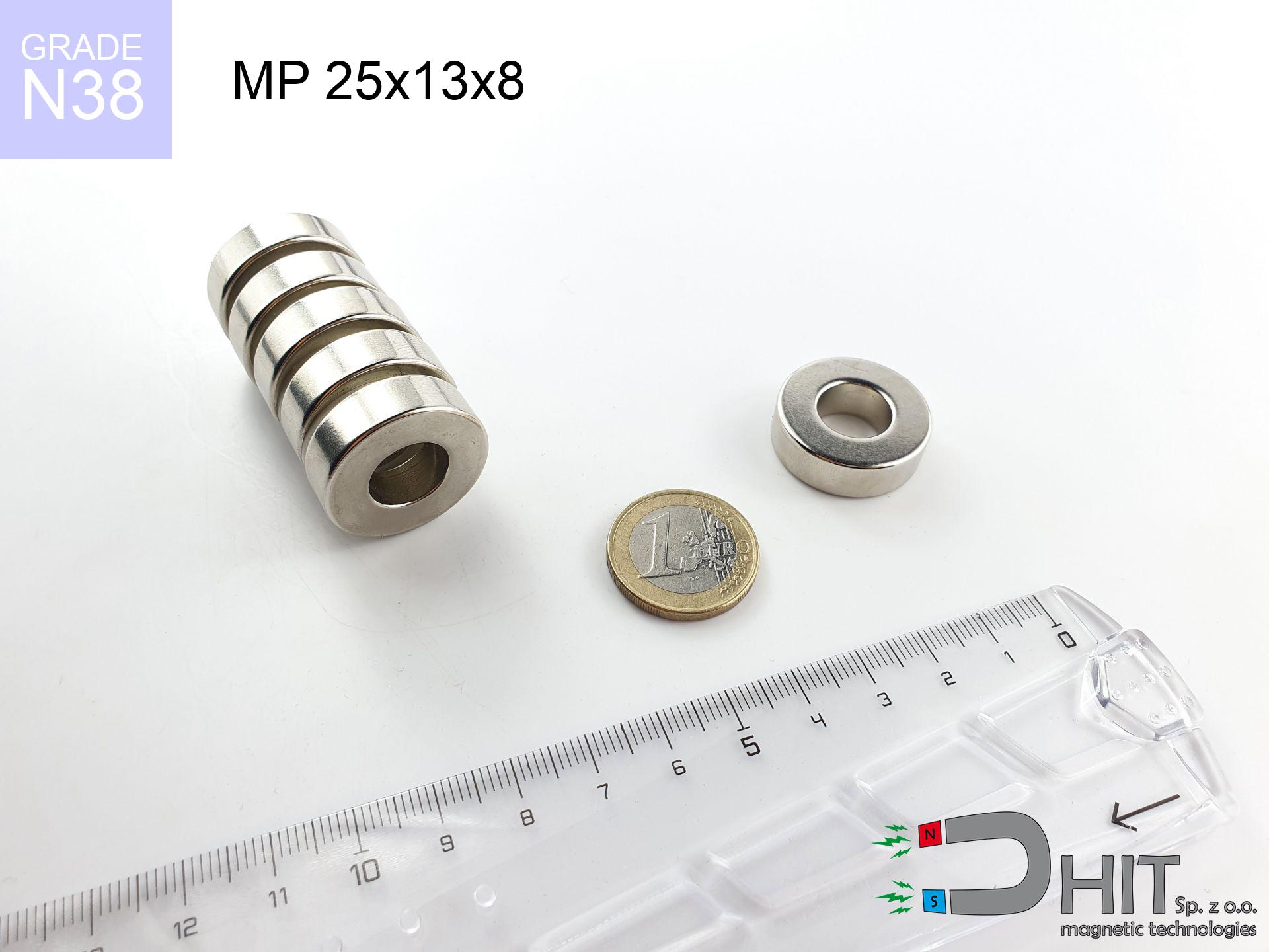
MP 25x13x8 / N38 - ring magnet
ring magnet
Catalog no 030191
GTIN/EAN: 5906301812081
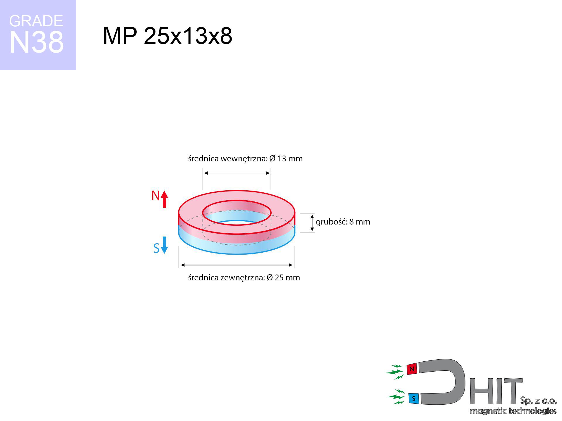
- Diameter
- 25 mm [±0,1 mm]
- internal diameter Ø
- 13 mm [±0,1 mm]
- Height
- 8 mm [±0,1 mm]
- Weight
- 21.49 g
- Magnetization Direction
- ↑ axial
- Coating
- [NiCuNi] Nickel
How we measure these parameters — certificates and measurements
11.00 zł net / pcs
13.53 zł with VAT (23% VAT) / pcs
bulk discounts:
Need more?Frequently asked questions
Where can I compare prices of ring magnets for mounting in Poland?
Are ring magnets resistant to damage?
Which ring magnet is suitable for an outdoor structure?
Where can I check the available sizes of neodymium ring magnets?
Engineering report for this magnet
Full PDF analysis: pull and shear force, effect of distance, temperature and plate thickness, safety distances and the demagnetization curve.
Call us now
+48 888 99 98 98
alternatively let us know using
contact form
the contact section.
Specifications and structure of a neodymium magnet can be estimated using our
power calculator.
Order by 14:00 and we’ll ship today!
Physical properties - MP 25x13x8 / N38 - ring magnet
Specification / characteristics - MP 25x13x8 / N38 - ring magnet
| properties | values |
|---|---|
| Cat. no. | 030191 |
| GTIN/EAN | 5906301812081 |
| Production/Distribution | Dhit sp. z o.o. |
| Country of origin | Poland / China / Germany |
| Customs code | 85059029 |
| Diameter | 25 mm [±0,1 mm] |
| internal diameter Ø | 13 mm [±0,1 mm] |
| Height | 8 mm [±0,1 mm] |
| Weight | 21.49 g |
| Magnetization Direction | ↑ axial |
| Load capacity ~ ? | 10.49 kg / 102.90 N |
| Magnetic Induction ~ ? | 334.09 mT / 3341 Gs |
| Coating | [NiCuNi] Nickel |
| Manufacturing Tolerance | ±0.1 mm |
Magnetic properties of material N38
| properties | values | units |
|---|---|---|
| Remanence Br ? | 12.2-12.6 | kGs |
| Remanence Br ? | 1220-1260 | mT |
| Coercivity bHc ? | 10.8-11.5 | kOe |
| Coercivity bHc ? | 860-915 | kA/m |
| Intrinsic coercivity iHc | ≥ 12 | kOe |
| Intrinsic coercivity iHc | ≥ 955 | kA/m |
| Energy product BHmax ? | 36-38 | BH max MGOe |
| Energy product BHmax ? | 287-303 | BH max KJ/m |
| Maximum working temperature ? | ≤ 80 | °C |
Physical properties of sintered neodymium magnets Nd2Fe14B at 20°C
| properties | values | units |
|---|---|---|
| Vickers hardness | ≥550 | Hv |
| Density | ≥7.4 | g/cm3 |
| Curie Temperature TC | 310 | °C |
| Curie Temperature TF | 590 | °F |
| Specific resistance | 150 | μΩ⋅cm |
| Bending strength | 250 | MPa |
| Compressive strength | 1000~1100 | MPa |
| Thermal expansion parallel (∥) to orientation (M) | (3-4) x 10-6 | °C-1 |
| Thermal expansion perpendicular (⊥) to orientation (M) | -(1-3) x 10-6 | °C-1 |
| Young's modulus | 1.7 x 10⁴ | kg/mm² |
Physical analysis of the magnet - technical parameters
The following values are the direct effect of a physical simulation. Results are based on models for the class Nd2Fe14B. Operational parameters might slightly differ. Treat these data as a reference point for designers.
Table 1: Static force (force vs distance) - power drop
MP 25x13x8 / N38
| Distance (mm) | Induction (Gauss) / mT | Pull Force (kg/lbs/g/N) | Risk Status |
|---|---|---|---|
| 0 mm |
5777 Gs
577.7 mT
|
10.49 kg / 23.13 lbs
10490.0 g / 102.9 N
|
critical level |
| 1 mm |
5310 Gs
531.0 mT
|
8.86 kg / 19.54 lbs
8861.7 g / 86.9 N
|
strong |
| 2 mm |
4846 Gs
484.6 mT
|
7.38 kg / 16.27 lbs
7379.4 g / 72.4 N
|
strong |
| 3 mm |
4397 Gs
439.7 mT
|
6.08 kg / 13.40 lbs
6077.4 g / 59.6 N
|
strong |
| 5 mm |
3576 Gs
357.6 mT
|
4.02 kg / 8.86 lbs
4019.0 g / 39.4 N
|
strong |
| 10 mm |
2073 Gs
207.3 mT
|
1.35 kg / 2.98 lbs
1350.2 g / 13.2 N
|
weak grip |
| 15 mm |
1231 Gs
123.1 mT
|
0.48 kg / 1.05 lbs
476.4 g / 4.7 N
|
weak grip |
| 20 mm |
773 Gs
77.3 mT
|
0.19 kg / 0.41 lbs
187.6 g / 1.8 N
|
weak grip |
| 30 mm |
356 Gs
35.6 mT
|
0.04 kg / 0.09 lbs
39.8 g / 0.4 N
|
weak grip |
| 50 mm |
115 Gs
11.5 mT
|
0.00 kg / 0.01 lbs
4.1 g / 0.0 N
|
weak grip |
Table 2: Sliding hold (wall)
MP 25x13x8 / N38
| Distance (mm) | Friction coefficient | Pull Force (kg/lbs/g/N) |
|---|---|---|
| 0 mm | Stal (~0.2) |
2.10 kg / 4.63 lbs
2098.0 g / 20.6 N
|
| 1 mm | Stal (~0.2) |
1.77 kg / 3.91 lbs
1772.0 g / 17.4 N
|
| 2 mm | Stal (~0.2) |
1.48 kg / 3.25 lbs
1476.0 g / 14.5 N
|
| 3 mm | Stal (~0.2) |
1.22 kg / 2.68 lbs
1216.0 g / 11.9 N
|
| 5 mm | Stal (~0.2) |
0.80 kg / 1.77 lbs
804.0 g / 7.9 N
|
| 10 mm | Stal (~0.2) |
0.27 kg / 0.60 lbs
270.0 g / 2.6 N
|
| 15 mm | Stal (~0.2) |
0.10 kg / 0.21 lbs
96.0 g / 0.9 N
|
| 20 mm | Stal (~0.2) |
0.04 kg / 0.08 lbs
38.0 g / 0.4 N
|
| 30 mm | Stal (~0.2) |
0.01 kg / 0.02 lbs
8.0 g / 0.1 N
|
| 50 mm | Stal (~0.2) |
0.00 kg / 0.00 lbs
0.0 g / 0.0 N
|
Table 3: Vertical assembly (shearing) - behavior on slippery surfaces
MP 25x13x8 / N38
| Surface type | Friction coefficient / % Mocy | Max load (kg/lbs/g/N) |
|---|---|---|
| Raw steel |
µ = 0.3
30% Nominalnej Siły
|
3.15 kg / 6.94 lbs
3147.0 g / 30.9 N
|
| Painted steel (standard) |
µ = 0.2
20% Nominalnej Siły
|
2.10 kg / 4.63 lbs
2098.0 g / 20.6 N
|
| Oily/slippery steel |
µ = 0.1
10% Nominalnej Siły
|
1.05 kg / 2.31 lbs
1049.0 g / 10.3 N
|
| Magnet with anti-slip rubber |
µ = 0.5
50% Nominalnej Siły
|
5.25 kg / 11.56 lbs
5245.0 g / 51.5 N
|
Table 4: Material efficiency (saturation) - power losses
MP 25x13x8 / N38
| Steel thickness (mm) | % power | Real pull force (kg/lbs/g/N) |
|---|---|---|
| 0.5 mm |
|
0.52 kg / 1.16 lbs
524.5 g / 5.1 N
|
| 1 mm |
|
1.31 kg / 2.89 lbs
1311.3 g / 12.9 N
|
| 2 mm |
|
2.62 kg / 5.78 lbs
2622.5 g / 25.7 N
|
| 3 mm |
|
3.93 kg / 8.67 lbs
3933.8 g / 38.6 N
|
| 5 mm |
|
6.56 kg / 14.45 lbs
6556.3 g / 64.3 N
|
| 10 mm |
|
10.49 kg / 23.13 lbs
10490.0 g / 102.9 N
|
| 11 mm |
|
10.49 kg / 23.13 lbs
10490.0 g / 102.9 N
|
| 12 mm |
|
10.49 kg / 23.13 lbs
10490.0 g / 102.9 N
|
Table 5: Working in heat (material behavior) - thermal limit
MP 25x13x8 / N38
| Ambient temp. (°C) | Power loss | Remaining pull (kg/lbs/g/N) | Status |
|---|---|---|---|
| 20 °C | 0.0% |
10.49 kg / 23.13 lbs
10490.0 g / 102.9 N
|
OK |
| 40 °C | -2.2% |
10.26 kg / 22.62 lbs
10259.2 g / 100.6 N
|
OK |
| 60 °C | -4.4% |
10.03 kg / 22.11 lbs
10028.4 g / 98.4 N
|
OK |
| 80 °C | -6.6% |
9.80 kg / 21.60 lbs
9797.7 g / 96.1 N
|
|
| 100 °C | -28.8% |
7.47 kg / 16.47 lbs
7468.9 g / 73.3 N
|
Table 6: Magnet-Magnet interaction (attraction) - field collision
MP 25x13x8 / N38
| Gap (mm) | Attraction (kg/lbs) (N-S) | Shear Strength (kg/lbs/g/N) | Repulsion (kg/lbs) (N-N) |
|---|---|---|---|
| 0 mm |
77.07 kg / 169.90 lbs
6 082 Gs
|
11.56 kg / 25.49 lbs
11560 g / 113.4 N
|
N/A |
| 1 mm |
71.01 kg / 156.55 lbs
11 091 Gs
|
10.65 kg / 23.48 lbs
10652 g / 104.5 N
|
63.91 kg / 140.90 lbs
~0 Gs
|
| 2 mm |
65.10 kg / 143.53 lbs
10 620 Gs
|
9.77 kg / 21.53 lbs
9766 g / 95.8 N
|
58.59 kg / 129.18 lbs
~0 Gs
|
| 3 mm |
59.50 kg / 131.17 lbs
10 153 Gs
|
8.92 kg / 19.68 lbs
8925 g / 87.6 N
|
53.55 kg / 118.06 lbs
~0 Gs
|
| 5 mm |
49.26 kg / 108.61 lbs
9 238 Gs
|
7.39 kg / 16.29 lbs
7389 g / 72.5 N
|
44.34 kg / 97.74 lbs
~0 Gs
|
| 10 mm |
29.53 kg / 65.10 lbs
7 152 Gs
|
4.43 kg / 9.76 lbs
4429 g / 43.4 N
|
26.57 kg / 58.59 lbs
~0 Gs
|
| 20 mm |
9.92 kg / 21.87 lbs
4 145 Gs
|
1.49 kg / 3.28 lbs
1488 g / 14.6 N
|
8.93 kg / 19.68 lbs
~0 Gs
|
| 50 mm |
0.61 kg / 1.33 lbs
1 024 Gs
|
0.09 kg / 0.20 lbs
91 g / 0.9 N
|
0.54 kg / 1.20 lbs
~0 Gs
|
| 60 mm |
0.29 kg / 0.64 lbs
712 Gs
|
0.04 kg / 0.10 lbs
44 g / 0.4 N
|
0.26 kg / 0.58 lbs
~0 Gs
|
| 70 mm |
0.15 kg / 0.34 lbs
514 Gs
|
0.02 kg / 0.05 lbs
23 g / 0.2 N
|
0.14 kg / 0.30 lbs
~0 Gs
|
| 80 mm |
0.08 kg / 0.19 lbs
383 Gs
|
0.01 kg / 0.03 lbs
13 g / 0.1 N
|
0.08 kg / 0.17 lbs
~0 Gs
|
| 90 mm |
0.05 kg / 0.11 lbs
293 Gs
|
0.01 kg / 0.02 lbs
7 g / 0.1 N
|
0.04 kg / 0.10 lbs
~0 Gs
|
| 100 mm |
0.03 kg / 0.07 lbs
230 Gs
|
0.00 kg / 0.01 lbs
5 g / 0.0 N
|
0.03 kg / 0.06 lbs
~0 Gs
|
Table 7: Safety (HSE) (implants) - warnings
MP 25x13x8 / N38
| Object / Device | Limit (Gauss) / mT | Safe distance |
|---|---|---|
| Pacemaker | 5 Gs (0.5 mT) | 17.0 cm |
| Hearing aid | 10 Gs (1.0 mT) | 13.5 cm |
| Timepiece | 20 Gs (2.0 mT) | 10.5 cm |
| Mobile device | 40 Gs (4.0 mT) | 8.0 cm |
| Remote | 50 Gs (5.0 mT) | 7.5 cm |
| Payment card | 400 Gs (40.0 mT) | 3.0 cm |
| HDD hard drive | 600 Gs (60.0 mT) | 2.5 cm |
Table 8: Impact energy (kinetic energy) - collision effects
MP 25x13x8 / N38
| Start from (mm) | Speed (km/h) | Energy (J) | Predicted outcome |
|---|---|---|---|
| 10 mm |
23.51 km/h
(6.53 m/s)
|
0.46 J | |
| 30 mm |
25.12 km/h
(6.98 m/s)
|
0.52 J | |
| 50 mm |
25.19 km/h
(7.00 m/s)
|
0.53 J | |
| 100 mm |
25.20 km/h
(7.00 m/s)
|
0.53 J |
Table 9: Coating parameters (durability)
MP 25x13x8 / N38
| Technical parameter | Value / Description |
|---|---|
| Coating type | [NiCuNi] Nickel |
| Layer structure | Nickel - Copper - Nickel |
| Layer thickness | 10-20 µm |
| Salt spray test (SST) ? | 24 h |
| Recommended environment | Indoors only (dry) |
Table 10: Electrical data (Flux)
MP 25x13x8 / N38
| Parameter | Value | SI Unit / Description |
|---|---|---|
| Magnetic Flux | 23 118 Mx | 231.2 µWb |
| Pc Coefficient | 1.04 | High (Stable) |
Table 11: Underwater work (magnet fishing)
MP 25x13x8 / N38
| Environment | Effective steel pull | Effect |
|---|---|---|
| Air (land) | 10.49 kg | Standard |
| Water (riverbed) |
12.01 kg
(+1.52 kg buoyancy gain)
|
+14.5% |
1. Shear force
*Note: On a vertical wall, the magnet holds just a fraction of its nominal pull.
2. Steel thickness impact
*Thin metal sheet (e.g. computer case) significantly weakens the holding force.
3. Heat tolerance
N38: the maximum material working temperature is 80°C. Permitted conditions also depend on the shape and magnetic circuit.
4. Demagnetization curve and operating point (B-H)
chart generated for the permeance coefficient Pc (Permeance Coefficient) = 1.04
This simulation demonstrates the magnetic stability of the selected magnet under specific geometric conditions. The solid red line represents the demagnetization curve (material potential), while the dashed blue line is the load line based on the magnet's geometry. The Pc (Permeance Coefficient), also known as the load line slope, is a dimensionless value that describes the relationship between the magnet's shape and its magnetic stability. The intersection of these two lines (the black dot) is the operating point — it determines the actual magnetic flux density generated by the magnet in this specific configuration. A higher Pc value means the magnet is more 'slender' (tall relative to its area), resulting in a higher operating point and better resistance to irreversible demagnetization caused by external fields or temperature. A value of 0.42 is relatively low (typical for flat magnets), meaning the operating point is closer to the 'knee' of the curve — caution is advised when operating at temperatures near the maximum limit to avoid strength loss.
Chemical composition
| iron (Fe) | 64% – 68% |
| neodymium (Nd) | 29% – 32% |
| boron (B) | 1.1% – 1.2% |
| dysprosium (Dy) | 0.5% – 2.0% |
| coating (Ni-Cu-Ni) | < 0.05% |
Ecology and recycling (GPSR)
| recyclability (EoL) | 100% |
| recycled raw materials | ~10% (pre-cons) |
| carbon footprint | low / zredukowany |
| waste code (EWC) | 16 02 16 |
Check out also offers
![SM 25x375 [2xM8] / N42 - magnetic separator](https://cdn3.dhit.pl/graphics/products/sm-25x375-2xm8-feg.jpg "SM 25x375 [2xM8] / N42 - magnetic separator")
![UMP 75x25 [M10x3] GW F200 PLATINIUM / N52 - search holder](https://cdn3.dhit.pl/graphics/products/ump-75x25-m10x3-gw-f200-platinium-tav.jpg "UMP 75x25 [M10x3] GW F200 PLATINIUM / N52 - search holder")
Advantages and disadvantages of rare earth magnets.
Advantages
- They retain attractive force for almost ten years – the drop is just ~1% (according to analyses),
- Magnets perfectly protect themselves against loss of magnetization caused by foreign field sources,
- In other words, due to the aesthetic surface of silver, the element is aesthetically pleasing,
- They are known for high magnetic induction at the operating surface, making them more effective,
- Due to their durability and thermal resistance, neodymium magnets can operate (depending on the shape) even at high temperatures reaching 230°C or more...
- Considering the ability of accurate forming and customization to unique solutions, magnetic components can be produced in a broad palette of shapes and sizes, which increases their versatility,
- Versatile presence in modern technologies – they are used in data components, electric motors, medical equipment, also multitasking production systems.
- Thanks to concentrated force, small magnets offer high operating force, in miniature format,
Limitations
- They are fragile upon heavy impacts. To avoid cracks, it is worth protecting magnets in a protective case. Such protection not only protects the magnet but also increases its resistance to damage
- Do not exceed this material temperature limit: 80°C. Overheating may permanently weaken the magnet.
- Magnets exposed to a humid environment can rust. Therefore during using outdoors, we recommend using waterproof magnets made of rubber, plastic or other material resistant to moisture
- We suggest a housing - magnetic mount, due to difficulties in realizing threads inside the magnet and complicated shapes.
- Potential hazard related to microscopic parts of magnets are risky, if swallowed, which becomes key in the aspect of protecting the youngest. Additionally, tiny parts of these devices can complicate diagnosis medical in case of swallowing.
- With budget limitations the cost of neodymium magnets can be a barrier,
Pull force analysis
Magnetic strength at its maximum – what it depends on?
- on a base made of structural steel, optimally conducting the magnetic flux
- whose transverse dimension reaches at least 10 mm
- with a plane perfectly flat
- without the slightest air gap between the magnet and steel
- under axial force vector (90-degree angle)
- at temperature room level
Magnet lifting force in use – key factors
- Space between surfaces – even a fraction of a millimeter of distance (caused e.g. by veneer or dirt) drastically reduces the pulling force, often by half at just 0.5 mm.
- Force direction – remember that the magnet has greatest strength perpendicularly. Under sliding down, the holding force drops significantly, often to levels of 20-30% of the nominal value.
- Substrate thickness – to utilize 100% power, the steel must be sufficiently thick. Thin sheet restricts the attraction force (the magnet "punches through" it).
- Material composition – different alloys attracts identically. Alloy additives worsen the attraction effect.
- Smoothness – full contact is obtained only on polished steel. Any scratches and bumps reduce the real contact area, weakening the magnet.
- Thermal environment – heating the magnet causes a temporary drop of induction. Check the thermal limit for a given model.
Lifting capacity was determined using a polished steel plate of optimal thickness (min. 20 mm), under vertically applied force, whereas under shearing force the lifting capacity is smaller. Additionally, even a minimal clearance between the magnet and the plate reduces the load capacity.
Precautions when working with neodymium magnets
Operating temperature
Do not overheat. Neodymium magnets are sensitive to heat. If you need operation above 80°C, ask us about HT versions (H, SH, UH).
Safe distance
Device Safety: Strong magnets can damage payment cards and delicate electronics (heart implants, hearing aids, mechanical watches).
Metal Allergy
Some people experience a sensitization to nickel, which is the standard coating for neodymium magnets. Extended handling can result in a rash. We strongly advise use safety gloves.
Do not give to children
Product intended for adults. Tiny parts pose a choking risk, leading to severe trauma. Store away from children and animals.
Fragile material
Neodymium magnets are ceramic materials, which means they are very brittle. Impact of two magnets will cause them cracking into shards.
Conscious usage
Before use, read the rules. Sudden snapping can destroy the magnet or hurt your hand. Think ahead.
Serious injuries
Watch your fingers. Two powerful magnets will join immediately with a force of massive weight, crushing anything in their path. Exercise extreme caution!
Precision electronics
GPS units and smartphones are highly susceptible to magnetism. Close proximity with a strong magnet can ruin the internal compass in your phone.
Do not drill into magnets
Combustion risk: Rare earth powder is highly flammable. Avoid machining magnets in home conditions as this risks ignition.
Health Danger
People with a ICD must keep an large gap from magnets. The magnetism can disrupt the functioning of the life-saving device.
Tabela kosztu i czasu dostawy
Płatność przed wysyłką:

GLS kurier
Przesyłka będzie u Ciebie za 2-3 dni
14.99 ZŁ

InPost Paczkomaty 24/7
Przesyłka będzie u Ciebie za 1-2 dni
12.30 ZŁ
Płatność przy odbiorze (pobranie):
GLS kurier
Przesyłka będzie u Ciebie za 1-2 dni
23.00 ZŁ