
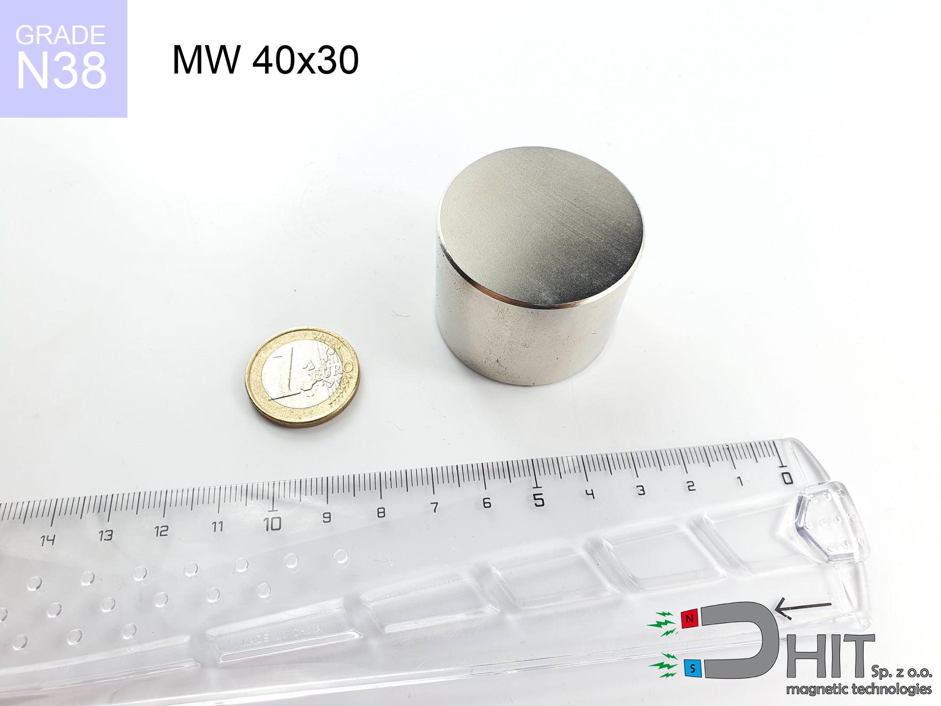
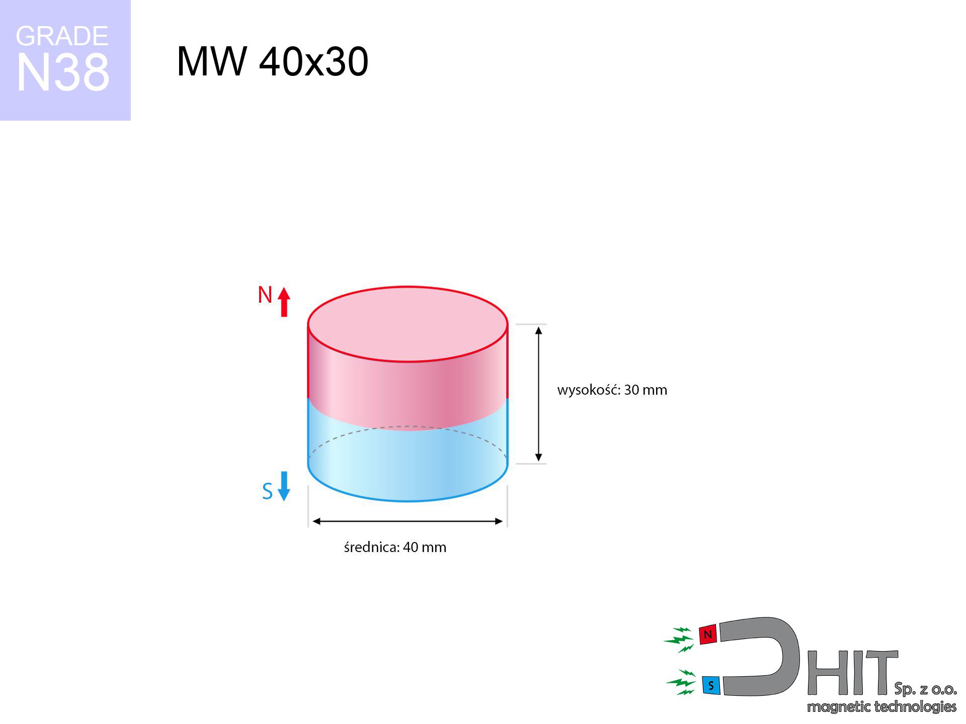
MW 40x30 / N38 - cylindrical magnet
cylindrical magnet
Catalog no 010068
GTIN/EAN: 5906301810674
Diameter Ø
40 mm [±0,1 mm]
Height
30 mm [±0,1 mm]
Weight
282.74 g
Magnetization Direction
→ diametrical
Load capacity
54.73 kg / 536.88 N
Magnetic Induction
515.71 mT / 5157 Gs
Coating
[NiCuNi] Nickel
104.80 ZŁ with VAT / pcs + price for transport
85.20 ZŁ net + 23% VAT / pcs
bulk discounts:
Need more?
Give us a call
+48 888 99 98 98
otherwise contact us via
our online form
through our site.
Parameters along with shape of neodymium magnets can be reviewed using our
power calculator.
Orders placed before 14:00 will be shipped the same business day.
Technical details - MW 40x30 / N38 - cylindrical magnet
Specification / characteristics - MW 40x30 / N38 - cylindrical magnet
| properties | values |
|---|---|
| Cat. no. | 010068 |
| GTIN/EAN | 5906301810674 |
| Production/Distribution | Dhit sp. z o.o. |
| Country of origin | Poland / China / Germany |
| Customs code | 85059029 |
| Diameter Ø | 40 mm [±0,1 mm] |
| Height | 30 mm [±0,1 mm] |
| Weight | 282.74 g |
| Magnetization Direction | → diametrical |
| Load capacity ~ ? | 54.73 kg / 536.88 N |
| Magnetic Induction ~ ? | 515.71 mT / 5157 Gs |
| Coating | [NiCuNi] Nickel |
| Manufacturing Tolerance | ±0.1 mm |
Magnetic properties of material N38
| properties | values | units |
|---|---|---|
| remenance Br [min. - max.] ? | 12.2-12.6 | kGs |
| remenance Br [min. - max.] ? | 1220-1260 | mT |
| coercivity bHc ? | 10.8-11.5 | kOe |
| coercivity bHc ? | 860-915 | kA/m |
| actual internal force iHc | ≥ 12 | kOe |
| actual internal force iHc | ≥ 955 | kA/m |
| energy density [min. - max.] ? | 36-38 | BH max MGOe |
| energy density [min. - max.] ? | 287-303 | BH max KJ/m |
| max. temperature ? | ≤ 80 | °C |
Physical properties of sintered neodymium magnets Nd2Fe14B at 20°C
| properties | values | units |
|---|---|---|
| Vickers hardness | ≥550 | Hv |
| Density | ≥7.4 | g/cm3 |
| Curie Temperature TC | 312 - 380 | °C |
| Curie Temperature TF | 593 - 716 | °F |
| Specific resistance | 150 | μΩ⋅cm |
| Bending strength | 250 | MPa |
| Compressive strength | 1000~1100 | MPa |
| Thermal expansion parallel (∥) to orientation (M) | (3-4) x 10-6 | °C-1 |
| Thermal expansion perpendicular (⊥) to orientation (M) | -(1-3) x 10-6 | °C-1 |
| Young's modulus | 1.7 x 10⁴ | kg/mm² |
Physical modeling of the magnet - technical parameters
These data are the direct effect of a mathematical calculation. Values rely on algorithms for the material Nd2Fe14B. Actual performance might slightly differ. Use these data as a supplementary guide during assembly planning.
Table 1: Static pull force (pull vs distance) - characteristics
MW 40x30 / N38
| Distance (mm) | Induction (Gauss) / mT | Pull Force (kg/lbs/g/N) | Risk Status |
|---|---|---|---|
| 0 mm |
5156 Gs
515.6 mT
|
54.73 kg / 120.66 lbs
54730.0 g / 536.9 N
|
crushing |
| 1 mm |
4900 Gs
490.0 mT
|
49.43 kg / 108.98 lbs
49432.0 g / 484.9 N
|
crushing |
| 2 mm |
4641 Gs
464.1 mT
|
44.33 kg / 97.74 lbs
44334.0 g / 434.9 N
|
crushing |
| 3 mm |
4383 Gs
438.3 mT
|
39.54 kg / 87.17 lbs
39538.7 g / 387.9 N
|
crushing |
| 5 mm |
3879 Gs
387.9 mT
|
30.98 kg / 68.30 lbs
30981.5 g / 303.9 N
|
crushing |
| 10 mm |
2773 Gs
277.3 mT
|
15.83 kg / 34.89 lbs
15826.7 g / 155.3 N
|
crushing |
| 15 mm |
1946 Gs
194.6 mT
|
7.79 kg / 17.18 lbs
7792.9 g / 76.4 N
|
warning |
| 20 mm |
1372 Gs
137.2 mT
|
3.88 kg / 8.55 lbs
3877.9 g / 38.0 N
|
warning |
| 30 mm |
723 Gs
72.3 mT
|
1.08 kg / 2.37 lbs
1076.5 g / 10.6 N
|
low risk |
| 50 mm |
258 Gs
25.8 mT
|
0.14 kg / 0.30 lbs
137.4 g / 1.3 N
|
low risk |
Table 2: Sliding capacity (wall)
MW 40x30 / N38
| Distance (mm) | Friction coefficient | Pull Force (kg/lbs/g/N) |
|---|---|---|
| 0 mm | Stal (~0.2) |
10.95 kg / 24.13 lbs
10946.0 g / 107.4 N
|
| 1 mm | Stal (~0.2) |
9.89 kg / 21.79 lbs
9886.0 g / 97.0 N
|
| 2 mm | Stal (~0.2) |
8.87 kg / 19.55 lbs
8866.0 g / 87.0 N
|
| 3 mm | Stal (~0.2) |
7.91 kg / 17.43 lbs
7908.0 g / 77.6 N
|
| 5 mm | Stal (~0.2) |
6.20 kg / 13.66 lbs
6196.0 g / 60.8 N
|
| 10 mm | Stal (~0.2) |
3.17 kg / 6.98 lbs
3166.0 g / 31.1 N
|
| 15 mm | Stal (~0.2) |
1.56 kg / 3.43 lbs
1558.0 g / 15.3 N
|
| 20 mm | Stal (~0.2) |
0.78 kg / 1.71 lbs
776.0 g / 7.6 N
|
| 30 mm | Stal (~0.2) |
0.22 kg / 0.48 lbs
216.0 g / 2.1 N
|
| 50 mm | Stal (~0.2) |
0.03 kg / 0.06 lbs
28.0 g / 0.3 N
|
Table 3: Vertical assembly (sliding) - vertical pull
MW 40x30 / N38
| Surface type | Friction coefficient / % Mocy | Max load (kg/lbs/g/N) |
|---|---|---|
| Raw steel |
µ = 0.3
30% Nominalnej Siły
|
16.42 kg / 36.20 lbs
16419.0 g / 161.1 N
|
| Painted steel (standard) |
µ = 0.2
20% Nominalnej Siły
|
10.95 kg / 24.13 lbs
10946.0 g / 107.4 N
|
| Oily/slippery steel |
µ = 0.1
10% Nominalnej Siły
|
5.47 kg / 12.07 lbs
5473.0 g / 53.7 N
|
| Magnet with anti-slip rubber |
µ = 0.5
50% Nominalnej Siły
|
27.37 kg / 60.33 lbs
27365.0 g / 268.5 N
|
Table 4: Steel thickness (substrate influence) - sheet metal selection
MW 40x30 / N38
| Steel thickness (mm) | % power | Real pull force (kg/lbs/g/N) |
|---|---|---|
| 0.5 mm |
|
1.82 kg / 4.02 lbs
1824.3 g / 17.9 N
|
| 1 mm |
|
4.56 kg / 10.05 lbs
4560.8 g / 44.7 N
|
| 2 mm |
|
9.12 kg / 20.11 lbs
9121.7 g / 89.5 N
|
| 3 mm |
|
13.68 kg / 30.16 lbs
13682.5 g / 134.2 N
|
| 5 mm |
|
22.80 kg / 50.27 lbs
22804.2 g / 223.7 N
|
| 10 mm |
|
45.61 kg / 100.55 lbs
45608.3 g / 447.4 N
|
| 11 mm |
|
50.17 kg / 110.60 lbs
50169.2 g / 492.2 N
|
| 12 mm |
|
54.73 kg / 120.66 lbs
54730.0 g / 536.9 N
|
Table 5: Thermal resistance (material behavior) - power drop
MW 40x30 / N38
| Ambient temp. (°C) | Power loss | Remaining pull (kg/lbs/g/N) | Status |
|---|---|---|---|
| 20 °C | 0.0% |
54.73 kg / 120.66 lbs
54730.0 g / 536.9 N
|
OK |
| 40 °C | -2.2% |
53.53 kg / 118.00 lbs
53525.9 g / 525.1 N
|
OK |
| 60 °C | -4.4% |
52.32 kg / 115.35 lbs
52321.9 g / 513.3 N
|
OK |
| 80 °C | -6.6% |
51.12 kg / 112.70 lbs
51117.8 g / 501.5 N
|
|
| 100 °C | -28.8% |
38.97 kg / 85.91 lbs
38967.8 g / 382.3 N
|
Table 6: Magnet-Magnet interaction (repulsion) - forces in the system
MW 40x30 / N38
| Gap (mm) | Attraction (kg/lbs) (N-S) | Sliding Force (kg/lbs/g/N) | Repulsion (kg/lbs) (N-N) |
|---|---|---|---|
| 0 mm |
205.97 kg / 454.08 lbs
5 879 Gs
|
30.89 kg / 68.11 lbs
30895 g / 303.1 N
|
N/A |
| 1 mm |
195.99 kg / 432.09 lbs
10 060 Gs
|
29.40 kg / 64.81 lbs
29399 g / 288.4 N
|
176.39 kg / 388.88 lbs
~0 Gs
|
| 2 mm |
186.03 kg / 410.12 lbs
9 800 Gs
|
27.90 kg / 61.52 lbs
27904 g / 273.7 N
|
167.42 kg / 369.11 lbs
~0 Gs
|
| 3 mm |
176.30 kg / 388.68 lbs
9 541 Gs
|
26.45 kg / 58.30 lbs
26445 g / 259.4 N
|
158.67 kg / 349.81 lbs
~0 Gs
|
| 5 mm |
157.67 kg / 347.60 lbs
9 023 Gs
|
23.65 kg / 52.14 lbs
23650 g / 232.0 N
|
141.90 kg / 312.84 lbs
~0 Gs
|
| 10 mm |
116.59 kg / 257.04 lbs
7 759 Gs
|
17.49 kg / 38.56 lbs
17489 g / 171.6 N
|
104.93 kg / 231.34 lbs
~0 Gs
|
| 20 mm |
59.56 kg / 131.31 lbs
5 545 Gs
|
8.93 kg / 19.70 lbs
8934 g / 87.6 N
|
53.60 kg / 118.18 lbs
~0 Gs
|
| 50 mm |
7.52 kg / 16.58 lbs
1 971 Gs
|
1.13 kg / 2.49 lbs
1128 g / 11.1 N
|
6.77 kg / 14.92 lbs
~0 Gs
|
| 60 mm |
4.05 kg / 8.93 lbs
1 446 Gs
|
0.61 kg / 1.34 lbs
608 g / 6.0 N
|
3.65 kg / 8.04 lbs
~0 Gs
|
| 70 mm |
2.28 kg / 5.03 lbs
1 085 Gs
|
0.34 kg / 0.75 lbs
342 g / 3.4 N
|
2.05 kg / 4.53 lbs
~0 Gs
|
| 80 mm |
1.34 kg / 2.96 lbs
832 Gs
|
0.20 kg / 0.44 lbs
201 g / 2.0 N
|
1.21 kg / 2.66 lbs
~0 Gs
|
| 90 mm |
0.82 kg / 1.80 lbs
650 Gs
|
0.12 kg / 0.27 lbs
123 g / 1.2 N
|
0.74 kg / 1.62 lbs
~0 Gs
|
| 100 mm |
0.52 kg / 1.14 lbs
517 Gs
|
0.08 kg / 0.17 lbs
78 g / 0.8 N
|
0.47 kg / 1.03 lbs
~0 Gs
|
Table 7: Hazards (electronics) - warnings
MW 40x30 / N38
| Object / Device | Limit (Gauss) / mT | Safe distance |
|---|---|---|
| Pacemaker | 5 Gs (0.5 mT) | 23.5 cm |
| Hearing aid | 10 Gs (1.0 mT) | 18.0 cm |
| Mechanical watch | 20 Gs (2.0 mT) | 14.0 cm |
| Phone / Smartphone | 40 Gs (4.0 mT) | 11.0 cm |
| Car key | 50 Gs (5.0 mT) | 10.0 cm |
| Payment card | 400 Gs (40.0 mT) | 4.5 cm |
| HDD hard drive | 600 Gs (60.0 mT) | 3.5 cm |
Table 8: Impact energy (kinetic energy) - collision effects
MW 40x30 / N38
| Start from (mm) | Speed (km/h) | Energy (J) | Predicted outcome |
|---|---|---|---|
| 10 mm |
16.37 km/h
(4.55 m/s)
|
2.92 J | |
| 30 mm |
24.60 km/h
(6.83 m/s)
|
6.60 J | |
| 50 mm |
31.42 km/h
(8.73 m/s)
|
10.77 J | |
| 100 mm |
44.37 km/h
(12.33 m/s)
|
21.48 J |
Table 9: Corrosion resistance
MW 40x30 / N38
| Technical parameter | Value / Description |
|---|---|
| Coating type | [NiCuNi] Nickel |
| Layer structure | Nickel - Copper - Nickel |
| Layer thickness | 10-20 µm |
| Salt spray test (SST) ? | 24 h |
| Recommended environment | Indoors only (dry) |
Table 10: Electrical data (Pc)
MW 40x30 / N38
| Parameter | Value | SI Unit / Description |
|---|---|---|
| Magnetic Flux | 65 488 Mx | 654.9 µWb |
| Pc Coefficient | 0.76 | High (Stable) |
Table 11: Submerged application
MW 40x30 / N38
| Environment | Effective steel pull | Effect |
|---|---|---|
| Air (land) | 54.73 kg | Standard |
| Water (riverbed) |
62.67 kg
(+7.94 kg buoyancy gain)
|
+14.5% |
1. Wall mount (shear)
*Warning: On a vertical wall, the magnet holds only approx. 20-30% of its nominal pull.
2. Steel thickness impact
*Thin metal sheet (e.g. 0.5mm PC case) drastically weakens the holding force.
3. Power loss vs temp
*For standard magnets, the critical limit is 80°C.
4. Demagnetization curve and operating point (B-H)
chart generated for the permeance coefficient Pc (Permeance Coefficient) = 0.76
The chart above illustrates the magnetic characteristics of the material within the second quadrant of the hysteresis loop. The solid red line represents the demagnetization curve (material potential), while the dashed blue line is the load line based on the magnet's geometry. The Pc (Permeance Coefficient), also known as the load line slope, is a dimensionless value that describes the relationship between the magnet's shape and its magnetic stability. The intersection of these two lines (the black dot) is the operating point — it determines the actual magnetic flux density generated by the magnet in this specific configuration. A higher Pc value means the magnet is more 'slender' (tall relative to its area), resulting in a higher operating point and better resistance to irreversible demagnetization caused by external fields or temperature. A value of 0.42 is relatively low (typical for flat magnets), meaning the operating point is closer to the 'knee' of the curve — caution is advised when operating at temperatures near the maximum limit to avoid strength loss.
Material specification
| iron (Fe) | 64% – 68% |
| neodymium (Nd) | 29% – 32% |
| boron (B) | 1.1% – 1.2% |
| dysprosium (Dy) | 0.5% – 2.0% |
| coating (Ni-Cu-Ni) | < 0.05% |
Sustainability
| recyclability (EoL) | 100% |
| recycled raw materials | ~10% (pre-cons) |
| carbon footprint | low / zredukowany |
| waste code (EWC) | 16 02 16 |
Other products
![HH 25x7.7 [M5] / N38 - through hole magnetic holder](https://cdn3.dhit.pl/graphics/products/hh-25x7.7-m5-pov.jpg "HH 25x7.7 [M5] / N38 - through hole magnetic holder")

![SM 25x400 [2xM8] / N52 - magnetic separator](https://cdn3.dhit.pl/graphics/products/sm-25x400-2xm8-hoj.jpg "SM 25x400 [2xM8] / N52 - magnetic separator")
![SM 25x300 [2xM8] / N52 - magnetic separator](https://cdn3.dhit.pl/graphics/products/sm-25x300-2xm8-dij.jpg "SM 25x300 [2xM8] / N52 - magnetic separator")
Strengths as well as weaknesses of neodymium magnets.
Benefits
- They do not lose power, even during approximately 10 years – the decrease in strength is only ~1% (according to tests),
- Neodymium magnets remain exceptionally resistant to loss of magnetic properties caused by external interference,
- In other words, due to the shiny finish of nickel, the element becomes visually attractive,
- They feature high magnetic induction at the operating surface, making them more effective,
- Neodymium magnets are characterized by very high magnetic induction on the magnet surface and can function (depending on the form) even at a temperature of 230°C or more...
- Possibility of accurate modeling and optimizing to individual applications,
- Huge importance in innovative solutions – they are commonly used in hard drives, drive modules, medical devices, and technologically advanced constructions.
- Thanks to their power density, small magnets offer high operating force, in miniature format,
Disadvantages
- They are prone to damage upon too strong impacts. To avoid cracks, it is worth securing magnets in special housings. Such protection not only shields the magnet but also increases its resistance to damage
- We warn that neodymium magnets can lose their strength at high temperatures. To prevent this, we advise our specialized [AH] magnets, which work effectively even at 230°C.
- Due to the susceptibility of magnets to corrosion in a humid environment, we advise using waterproof magnets made of rubber, plastic or other material resistant to moisture, when using outdoors
- We recommend a housing - magnetic mount, due to difficulties in creating nuts inside the magnet and complicated forms.
- Potential hazard to health – tiny shards of magnets pose a threat, when accidentally swallowed, which gains importance in the context of child safety. It is also worth noting that tiny parts of these devices can be problematic in diagnostics medical after entering the body.
- Higher cost of purchase is a significant factor to consider compared to ceramic magnets, especially in budget applications
Pull force analysis
Maximum magnetic pulling force – what affects it?
- using a base made of high-permeability steel, serving as a ideal flux conductor
- with a cross-section no less than 10 mm
- with an ground contact surface
- under conditions of ideal adhesion (metal-to-metal)
- during pulling in a direction vertical to the plane
- at room temperature
Key elements affecting lifting force
- Space between surfaces – every millimeter of separation (caused e.g. by varnish or unevenness) drastically reduces the pulling force, often by half at just 0.5 mm.
- Load vector – maximum parameter is available only during perpendicular pulling. The force required to slide of the magnet along the surface is usually many times smaller (approx. 1/5 of the lifting capacity).
- Element thickness – to utilize 100% power, the steel must be sufficiently thick. Paper-thin metal restricts the lifting capacity (the magnet "punches through" it).
- Metal type – not every steel attracts identically. High carbon content worsen the attraction effect.
- Smoothness – ideal contact is obtained only on polished steel. Rough texture reduce the real contact area, weakening the magnet.
- Thermal environment – temperature increase results in weakening of induction. It is worth remembering the maximum operating temperature for a given model.
Lifting capacity testing was performed on a smooth plate of optimal thickness, under perpendicular forces, in contrast under attempts to slide the magnet the holding force is lower. Moreover, even a minimal clearance between the magnet and the plate decreases the lifting capacity.
H&S for magnets
Maximum temperature
Standard neodymium magnets (grade N) undergo demagnetization when the temperature exceeds 80°C. Damage is permanent.
Precision electronics
GPS units and smartphones are extremely sensitive to magnetism. Close proximity with a strong magnet can decalibrate the sensors in your phone.
Metal Allergy
It is widely known that nickel (the usual finish) is a strong allergen. If you have an allergy, refrain from touching magnets with bare hands and opt for coated magnets.
Crushing force
Big blocks can smash fingers in a fraction of a second. Under no circumstances place your hand betwixt two strong magnets.
Beware of splinters
Watch out for shards. Magnets can fracture upon uncontrolled impact, launching sharp fragments into the air. Eye protection is mandatory.
Electronic hazard
Avoid bringing magnets near a wallet, computer, or TV. The magnetic field can destroy these devices and erase data from cards.
Medical interference
Patients with a pacemaker have to maintain an absolute distance from magnets. The magnetic field can stop the functioning of the life-saving device.
Do not underestimate power
Handle with care. Rare earth magnets attract from a long distance and connect with huge force, often quicker than you can react.
Machining danger
Dust produced during grinding of magnets is combustible. Do not drill into magnets without proper cooling and knowledge.
Danger to the youngest
Strictly keep magnets out of reach of children. Risk of swallowing is significant, and the consequences of magnets connecting inside the body are fatal.
Tabela kosztu i czasu dostawy
Płatność przed wysyłką:

GLS kurier
Przesyłka będzie u Ciebie za 2-3 dni
14.99 ZŁ

InPost Paczkomaty 24/7
Przesyłka będzie u Ciebie za 1-2 dni
12.30 ZŁ
Płatność przy odbiorze (pobranie):
GLS kurier
Przesyłka będzie u Ciebie za 1-2 dni
23.00 ZŁ
Rate the product
Your rating