
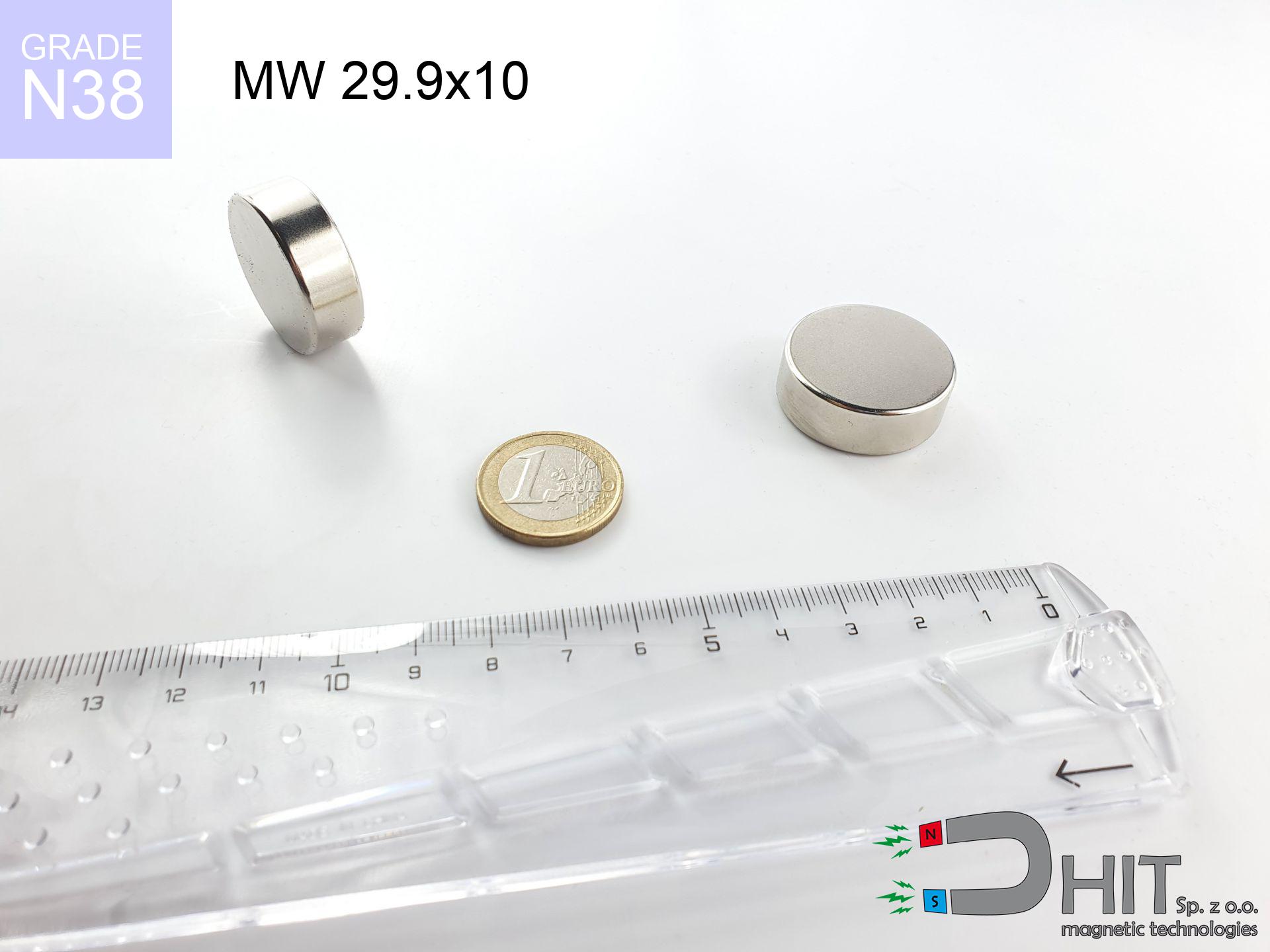
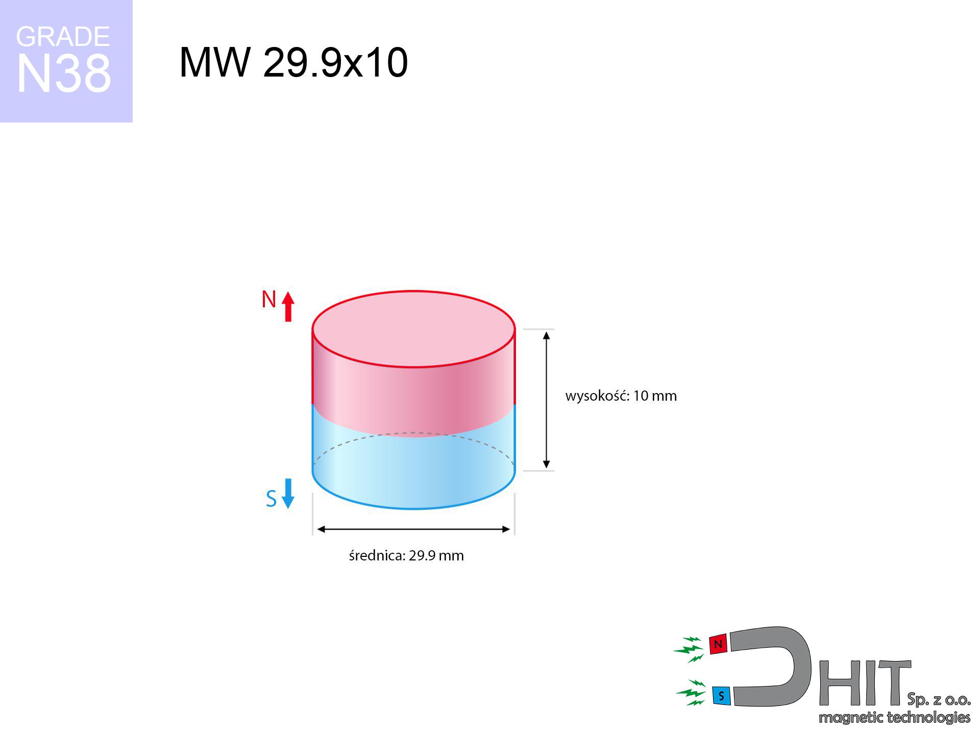
MW 29.9x10 / N38 - cylindrical magnet
cylindrical magnet
Catalog no 010052
GTIN/EAN: 5906301810513
Diameter Ø
29.9 mm [±0,1 mm]
Height
10 mm [±0,1 mm]
Weight
52.66 g
Magnetization Direction
→ diametrical
Load capacity
21.50 kg / 210.90 N
Magnetic Induction
344.60 mT / 3446 Gs
Coating
[NiCuNi] Nickel
24.60 ZŁ with VAT / pcs + price for transport
20.00 ZŁ net + 23% VAT / pcs
bulk discounts:
Need more?
Call us
+48 22 499 98 98
or drop us a message by means of
contact form
the contact section.
Weight and structure of neodymium magnets can be calculated on our
our magnetic calculator.
Same-day shipping for orders placed before 14:00.
Technical of the product - MW 29.9x10 / N38 - cylindrical magnet
Specification / characteristics - MW 29.9x10 / N38 - cylindrical magnet
| properties | values |
|---|---|
| Cat. no. | 010052 |
| GTIN/EAN | 5906301810513 |
| Production/Distribution | Dhit sp. z o.o. |
| Country of origin | Poland / China / Germany |
| Customs code | 85059029 |
| Diameter Ø | 29.9 mm [±0,1 mm] |
| Height | 10 mm [±0,1 mm] |
| Weight | 52.66 g |
| Magnetization Direction | → diametrical |
| Load capacity ~ ? | 21.50 kg / 210.90 N |
| Magnetic Induction ~ ? | 344.60 mT / 3446 Gs |
| Coating | [NiCuNi] Nickel |
| Manufacturing Tolerance | ±0.1 mm |
Magnetic properties of material N38
| properties | values | units |
|---|---|---|
| remenance Br [min. - max.] ? | 12.2-12.6 | kGs |
| remenance Br [min. - max.] ? | 1220-1260 | mT |
| coercivity bHc ? | 10.8-11.5 | kOe |
| coercivity bHc ? | 860-915 | kA/m |
| actual internal force iHc | ≥ 12 | kOe |
| actual internal force iHc | ≥ 955 | kA/m |
| energy density [min. - max.] ? | 36-38 | BH max MGOe |
| energy density [min. - max.] ? | 287-303 | BH max KJ/m |
| max. temperature ? | ≤ 80 | °C |
Physical properties of sintered neodymium magnets Nd2Fe14B at 20°C
| properties | values | units |
|---|---|---|
| Vickers hardness | ≥550 | Hv |
| Density | ≥7.4 | g/cm3 |
| Curie Temperature TC | 312 - 380 | °C |
| Curie Temperature TF | 593 - 716 | °F |
| Specific resistance | 150 | μΩ⋅cm |
| Bending strength | 250 | MPa |
| Compressive strength | 1000~1100 | MPa |
| Thermal expansion parallel (∥) to orientation (M) | (3-4) x 10-6 | °C-1 |
| Thermal expansion perpendicular (⊥) to orientation (M) | -(1-3) x 10-6 | °C-1 |
| Young's modulus | 1.7 x 10⁴ | kg/mm² |
Physical simulation of the product - report
Presented data represent the direct effect of a physical simulation. Values are based on models for the material Nd2Fe14B. Real-world conditions may differ. Treat these calculations as a supplementary guide for designers.
Table 1: Static pull force (force vs gap) - power drop
MW 29.9x10 / N38
| Distance (mm) | Induction (Gauss) / mT | Pull Force (kg/lbs/g/N) | Risk Status |
|---|---|---|---|
| 0 mm |
3445 Gs
344.5 mT
|
21.50 kg / 47.40 lbs
21500.0 g / 210.9 N
|
critical level |
| 1 mm |
3261 Gs
326.1 mT
|
19.26 kg / 42.45 lbs
19256.6 g / 188.9 N
|
critical level |
| 2 mm |
3059 Gs
305.9 mT
|
16.95 kg / 37.36 lbs
16947.4 g / 166.3 N
|
critical level |
| 3 mm |
2848 Gs
284.8 mT
|
14.70 kg / 32.40 lbs
14696.2 g / 144.2 N
|
critical level |
| 5 mm |
2425 Gs
242.5 mT
|
10.65 kg / 23.48 lbs
10650.1 g / 104.5 N
|
critical level |
| 10 mm |
1519 Gs
151.9 mT
|
4.18 kg / 9.21 lbs
4178.4 g / 41.0 N
|
warning |
| 15 mm |
930 Gs
93.0 mT
|
1.57 kg / 3.45 lbs
1565.8 g / 15.4 N
|
safe |
| 20 mm |
583 Gs
58.3 mT
|
0.62 kg / 1.36 lbs
616.0 g / 6.0 N
|
safe |
| 30 mm |
258 Gs
25.8 mT
|
0.12 kg / 0.27 lbs
121.0 g / 1.2 N
|
safe |
| 50 mm |
76 Gs
7.6 mT
|
0.01 kg / 0.02 lbs
10.4 g / 0.1 N
|
safe |
Table 2: Vertical force (vertical surface)
MW 29.9x10 / N38
| Distance (mm) | Friction coefficient | Pull Force (kg/lbs/g/N) |
|---|---|---|
| 0 mm | Stal (~0.2) |
4.30 kg / 9.48 lbs
4300.0 g / 42.2 N
|
| 1 mm | Stal (~0.2) |
3.85 kg / 8.49 lbs
3852.0 g / 37.8 N
|
| 2 mm | Stal (~0.2) |
3.39 kg / 7.47 lbs
3390.0 g / 33.3 N
|
| 3 mm | Stal (~0.2) |
2.94 kg / 6.48 lbs
2940.0 g / 28.8 N
|
| 5 mm | Stal (~0.2) |
2.13 kg / 4.70 lbs
2130.0 g / 20.9 N
|
| 10 mm | Stal (~0.2) |
0.84 kg / 1.84 lbs
836.0 g / 8.2 N
|
| 15 mm | Stal (~0.2) |
0.31 kg / 0.69 lbs
314.0 g / 3.1 N
|
| 20 mm | Stal (~0.2) |
0.12 kg / 0.27 lbs
124.0 g / 1.2 N
|
| 30 mm | Stal (~0.2) |
0.02 kg / 0.05 lbs
24.0 g / 0.2 N
|
| 50 mm | Stal (~0.2) |
0.00 kg / 0.00 lbs
2.0 g / 0.0 N
|
Table 3: Wall mounting (shearing) - vertical pull
MW 29.9x10 / N38
| Surface type | Friction coefficient / % Mocy | Max load (kg/lbs/g/N) |
|---|---|---|
| Raw steel |
µ = 0.3
30% Nominalnej Siły
|
6.45 kg / 14.22 lbs
6450.0 g / 63.3 N
|
| Painted steel (standard) |
µ = 0.2
20% Nominalnej Siły
|
4.30 kg / 9.48 lbs
4300.0 g / 42.2 N
|
| Oily/slippery steel |
µ = 0.1
10% Nominalnej Siły
|
2.15 kg / 4.74 lbs
2150.0 g / 21.1 N
|
| Magnet with anti-slip rubber |
µ = 0.5
50% Nominalnej Siły
|
10.75 kg / 23.70 lbs
10750.0 g / 105.5 N
|
Table 4: Steel thickness (substrate influence) - sheet metal selection
MW 29.9x10 / N38
| Steel thickness (mm) | % power | Real pull force (kg/lbs/g/N) |
|---|---|---|
| 0.5 mm |
|
1.08 kg / 2.37 lbs
1075.0 g / 10.5 N
|
| 1 mm |
|
2.69 kg / 5.92 lbs
2687.5 g / 26.4 N
|
| 2 mm |
|
5.38 kg / 11.85 lbs
5375.0 g / 52.7 N
|
| 3 mm |
|
8.06 kg / 17.77 lbs
8062.5 g / 79.1 N
|
| 5 mm |
|
13.44 kg / 29.62 lbs
13437.5 g / 131.8 N
|
| 10 mm |
|
21.50 kg / 47.40 lbs
21500.0 g / 210.9 N
|
| 11 mm |
|
21.50 kg / 47.40 lbs
21500.0 g / 210.9 N
|
| 12 mm |
|
21.50 kg / 47.40 lbs
21500.0 g / 210.9 N
|
Table 5: Thermal resistance (stability) - thermal limit
MW 29.9x10 / N38
| Ambient temp. (°C) | Power loss | Remaining pull (kg/lbs/g/N) | Status |
|---|---|---|---|
| 20 °C | 0.0% |
21.50 kg / 47.40 lbs
21500.0 g / 210.9 N
|
OK |
| 40 °C | -2.2% |
21.03 kg / 46.36 lbs
21027.0 g / 206.3 N
|
OK |
| 60 °C | -4.4% |
20.55 kg / 45.31 lbs
20554.0 g / 201.6 N
|
|
| 80 °C | -6.6% |
20.08 kg / 44.27 lbs
20081.0 g / 197.0 N
|
|
| 100 °C | -28.8% |
15.31 kg / 33.75 lbs
15308.0 g / 150.2 N
|
Table 6: Two magnets (repulsion) - field collision
MW 29.9x10 / N38
| Gap (mm) | Attraction (kg/lbs) (N-S) | Shear Force (kg/lbs/g/N) | Repulsion (kg/lbs) (N-N) |
|---|---|---|---|
| 0 mm |
51.38 kg / 113.28 lbs
4 963 Gs
|
7.71 kg / 16.99 lbs
7708 g / 75.6 N
|
N/A |
| 1 mm |
48.76 kg / 107.50 lbs
6 712 Gs
|
7.31 kg / 16.12 lbs
7314 g / 71.7 N
|
43.88 kg / 96.75 lbs
~0 Gs
|
| 2 mm |
46.02 kg / 101.46 lbs
6 521 Gs
|
6.90 kg / 15.22 lbs
6903 g / 67.7 N
|
41.42 kg / 91.32 lbs
~0 Gs
|
| 3 mm |
43.26 kg / 95.37 lbs
6 322 Gs
|
6.49 kg / 14.31 lbs
6489 g / 63.7 N
|
38.93 kg / 85.83 lbs
~0 Gs
|
| 5 mm |
37.78 kg / 83.30 lbs
5 909 Gs
|
5.67 kg / 12.49 lbs
5667 g / 55.6 N
|
34.00 kg / 74.97 lbs
~0 Gs
|
| 10 mm |
25.45 kg / 56.11 lbs
4 850 Gs
|
3.82 kg / 8.42 lbs
3818 g / 37.5 N
|
22.91 kg / 50.50 lbs
~0 Gs
|
| 20 mm |
9.99 kg / 22.02 lbs
3 038 Gs
|
1.50 kg / 3.30 lbs
1498 g / 14.7 N
|
8.99 kg / 19.81 lbs
~0 Gs
|
| 50 mm |
0.63 kg / 1.38 lbs
761 Gs
|
0.09 kg / 0.21 lbs
94 g / 0.9 N
|
0.56 kg / 1.24 lbs
~0 Gs
|
| 60 mm |
0.29 kg / 0.64 lbs
517 Gs
|
0.04 kg / 0.10 lbs
43 g / 0.4 N
|
0.26 kg / 0.57 lbs
~0 Gs
|
| 70 mm |
0.14 kg / 0.32 lbs
364 Gs
|
0.02 kg / 0.05 lbs
22 g / 0.2 N
|
0.13 kg / 0.28 lbs
~0 Gs
|
| 80 mm |
0.08 kg / 0.17 lbs
265 Gs
|
0.01 kg / 0.03 lbs
11 g / 0.1 N
|
0.07 kg / 0.15 lbs
~0 Gs
|
| 90 mm |
0.04 kg / 0.09 lbs
198 Gs
|
0.01 kg / 0.01 lbs
6 g / 0.1 N
|
0.04 kg / 0.08 lbs
~0 Gs
|
| 100 mm |
0.02 kg / 0.05 lbs
152 Gs
|
0.00 kg / 0.01 lbs
4 g / 0.0 N
|
0.02 kg / 0.05 lbs
~0 Gs
|
Table 7: Safety (HSE) (electronics) - warnings
MW 29.9x10 / N38
| Object / Device | Limit (Gauss) / mT | Safe distance |
|---|---|---|
| Pacemaker | 5 Gs (0.5 mT) | 13.5 cm |
| Hearing aid | 10 Gs (1.0 mT) | 11.0 cm |
| Timepiece | 20 Gs (2.0 mT) | 8.5 cm |
| Phone / Smartphone | 40 Gs (4.0 mT) | 6.5 cm |
| Car key | 50 Gs (5.0 mT) | 6.0 cm |
| Payment card | 400 Gs (40.0 mT) | 2.5 cm |
| HDD hard drive | 600 Gs (60.0 mT) | 2.0 cm |
Table 8: Dynamics (kinetic energy) - collision effects
MW 29.9x10 / N38
| Start from (mm) | Speed (km/h) | Energy (J) | Predicted outcome |
|---|---|---|---|
| 10 mm |
22.72 km/h
(6.31 m/s)
|
1.05 J | |
| 30 mm |
35.42 km/h
(9.84 m/s)
|
2.55 J | |
| 50 mm |
45.58 km/h
(12.66 m/s)
|
4.22 J | |
| 100 mm |
64.44 km/h
(17.90 m/s)
|
8.44 J |
Table 9: Corrosion resistance
MW 29.9x10 / N38
| Technical parameter | Value / Description |
|---|---|
| Coating type | [NiCuNi] Nickel |
| Layer structure | Nickel - Copper - Nickel |
| Layer thickness | 10-20 µm |
| Salt spray test (SST) ? | 24 h |
| Recommended environment | Indoors only (dry) |
Table 10: Electrical data (Pc)
MW 29.9x10 / N38
| Parameter | Value | SI Unit / Description |
|---|---|---|
| Magnetic Flux | 25 588 Mx | 255.9 µWb |
| Pc Coefficient | 0.44 | Low (Flat) |
Table 11: Underwater work (magnet fishing)
MW 29.9x10 / N38
| Environment | Effective steel pull | Effect |
|---|---|---|
| Air (land) | 21.50 kg | Standard |
| Water (riverbed) |
24.62 kg
(+3.12 kg buoyancy gain)
|
+14.5% |
1. Sliding resistance
*Note: On a vertical wall, the magnet holds only a fraction of its perpendicular strength.
2. Efficiency vs thickness
*Thin metal sheet (e.g. computer case) drastically limits the holding force.
3. Heat tolerance
*For N38 material, the safety limit is 80°C.
4. Demagnetization curve and operating point (B-H)
chart generated for the permeance coefficient Pc (Permeance Coefficient) = 0.44
This simulation demonstrates the magnetic stability of the selected magnet under specific geometric conditions. The solid red line represents the demagnetization curve (material potential), while the dashed blue line is the load line based on the magnet's geometry. The Pc (Permeance Coefficient), also known as the load line slope, is a dimensionless value that describes the relationship between the magnet's shape and its magnetic stability. The intersection of these two lines (the black dot) is the operating point — it determines the actual magnetic flux density generated by the magnet in this specific configuration. A higher Pc value means the magnet is more 'slender' (tall relative to its area), resulting in a higher operating point and better resistance to irreversible demagnetization caused by external fields or temperature. A value of 0.42 is relatively low (typical for flat magnets), meaning the operating point is closer to the 'knee' of the curve — caution is advised when operating at temperatures near the maximum limit to avoid strength loss.
Material specification
| iron (Fe) | 64% – 68% |
| neodymium (Nd) | 29% – 32% |
| boron (B) | 1.1% – 1.2% |
| dysprosium (Dy) | 0.5% – 2.0% |
| coating (Ni-Cu-Ni) | < 0.05% |
Ecology and recycling (GPSR)
| recyclability (EoL) | 100% |
| recycled raw materials | ~10% (pre-cons) |
| carbon footprint | low / zredukowany |
| waste code (EWC) | 16 02 16 |
Check out also proposals


![SM 32x125 [2xM8] / N52 - magnetic separator](https://cdn3.dhit.pl/graphics/products/sm-32x125-2xm8-moj.jpg "SM 32x125 [2xM8] / N52 - magnetic separator")
![UMP 135x40 [M10+M12] GW F 600 kg / N38 - search holder](https://cdn3.dhit.pl/graphics/products/ump135x40-m10+m12-gw-f-600-kg-luz.jpg "UMP 135x40 [M10+M12] GW F 600 kg / N38 - search holder")
Pros as well as cons of Nd2Fe14B magnets.
Pros
- They virtually do not lose strength, because even after 10 years the performance loss is only ~1% (in laboratory conditions),
- Magnets perfectly protect themselves against demagnetization caused by external fields,
- Thanks to the metallic finish, the layer of Ni-Cu-Ni, gold, or silver-plated gives an aesthetic appearance,
- Neodymium magnets achieve maximum magnetic induction on a contact point, which increases force concentration,
- Through (appropriate) combination of ingredients, they can achieve high thermal resistance, enabling functioning at temperatures approaching 230°C and above...
- Possibility of detailed forming as well as adjusting to precise applications,
- Universal use in innovative solutions – they serve a role in HDD drives, electric drive systems, medical devices, and industrial machines.
- Thanks to concentrated force, small magnets offer high operating force, in miniature format,
Cons
- At very strong impacts they can crack, therefore we advise placing them in special holders. A metal housing provides additional protection against damage and increases the magnet's durability.
- We warn that neodymium magnets can reduce their power at high temperatures. To prevent this, we advise our specialized [AH] magnets, which work effectively even at 230°C.
- Magnets exposed to a humid environment can corrode. Therefore during using outdoors, we recommend using water-impermeable magnets made of rubber, plastic or other material resistant to moisture
- Due to limitations in realizing threads and complicated forms in magnets, we recommend using a housing - magnetic mechanism.
- Potential hazard related to microscopic parts of magnets can be dangerous, in case of ingestion, which gains importance in the context of child safety. It is also worth noting that tiny parts of these products can complicate diagnosis medical after entering the body.
- Higher cost of purchase is one of the disadvantages compared to ceramic magnets, especially in budget applications
Lifting parameters
Maximum lifting capacity of the magnet – what contributes to it?
- on a block made of structural steel, perfectly concentrating the magnetic flux
- with a thickness minimum 10 mm
- with an ground contact surface
- without the slightest air gap between the magnet and steel
- under vertical force direction (90-degree angle)
- in stable room temperature
Magnet lifting force in use – key factors
- Distance (betwixt the magnet and the plate), as even a very small distance (e.g. 0.5 mm) can cause a reduction in lifting capacity by up to 50% (this also applies to paint, corrosion or dirt).
- Loading method – catalog parameter refers to pulling vertically. When applying parallel force, the magnet exhibits much less (typically approx. 20-30% of nominal force).
- Substrate thickness – for full efficiency, the steel must be adequately massive. Paper-thin metal limits the attraction force (the magnet "punches through" it).
- Steel grade – the best choice is pure iron steel. Hardened steels may have worse magnetic properties.
- Surface finish – ideal contact is possible only on smooth steel. Any scratches and bumps reduce the real contact area, weakening the magnet.
- Operating temperature – NdFeB sinters have a sensitivity to temperature. When it is hot they lose power, and at low temperatures gain strength (up to a certain limit).
Lifting capacity was assessed using a polished steel plate of suitable thickness (min. 20 mm), under perpendicular detachment force, however under parallel forces the lifting capacity is smaller. In addition, even a slight gap between the magnet and the plate reduces the holding force.
H&S for magnets
Keep away from computers
Do not bring magnets close to a wallet, laptop, or screen. The magnetism can irreversibly ruin these devices and erase data from cards.
Nickel allergy
A percentage of the population have a sensitization to Ni, which is the common plating for NdFeB magnets. Prolonged contact can result in skin redness. We suggest wear protective gloves.
Heat warning
Regular neodymium magnets (grade N) undergo demagnetization when the temperature surpasses 80°C. Damage is permanent.
Pacemakers
Patients with a heart stimulator should keep an safe separation from magnets. The magnetism can disrupt the functioning of the life-saving device.
Fire risk
Machining of neodymium magnets carries a risk of fire risk. Neodymium dust oxidizes rapidly with oxygen and is difficult to extinguish.
Crushing risk
Danger of trauma: The pulling power is so great that it can cause blood blisters, pinching, and broken bones. Use thick gloves.
Swallowing risk
Always store magnets away from children. Ingestion danger is significant, and the consequences of magnets clamping inside the body are fatal.
Magnet fragility
Neodymium magnets are sintered ceramics, meaning they are fragile like glass. Impact of two magnets leads to them shattering into shards.
Handling guide
Exercise caution. Rare earth magnets attract from a distance and snap with massive power, often quicker than you can move away.
Impact on smartphones
An intense magnetic field interferes with the functioning of magnetometers in smartphones and GPS navigation. Do not bring magnets close to a smartphone to avoid breaking the sensors.
Tabela kosztu i czasu dostawy
Płatność przed wysyłką:

GLS kurier
Przesyłka będzie u Ciebie za 2-3 dni
14.99 ZŁ

InPost Paczkomaty 24/7
Przesyłka będzie u Ciebie za 1-2 dni
12.30 ZŁ
Płatność przy odbiorze (pobranie):
GLS kurier
Przesyłka będzie u Ciebie za 1-2 dni
23.00 ZŁ
Rate the product
Your rating