
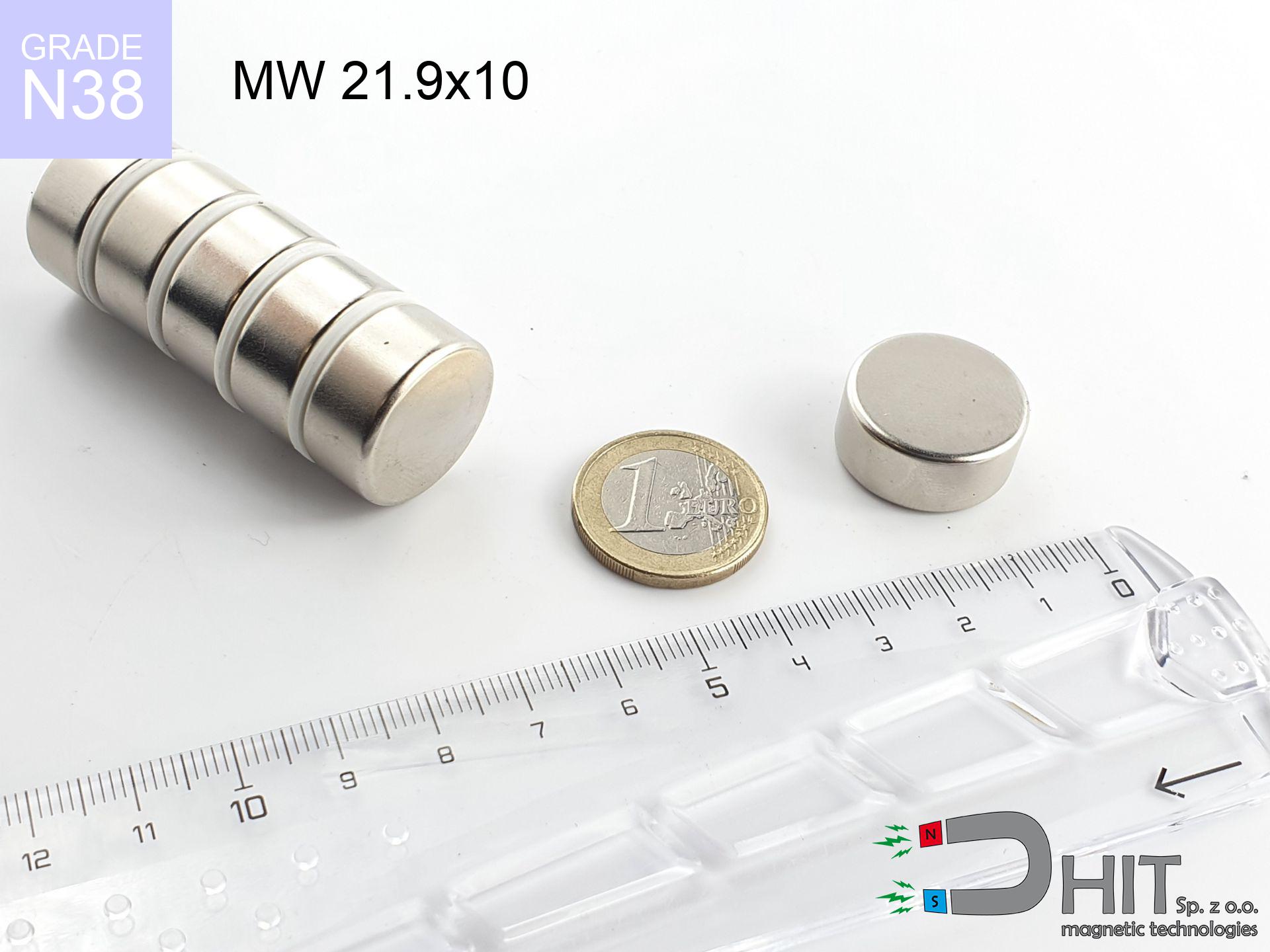
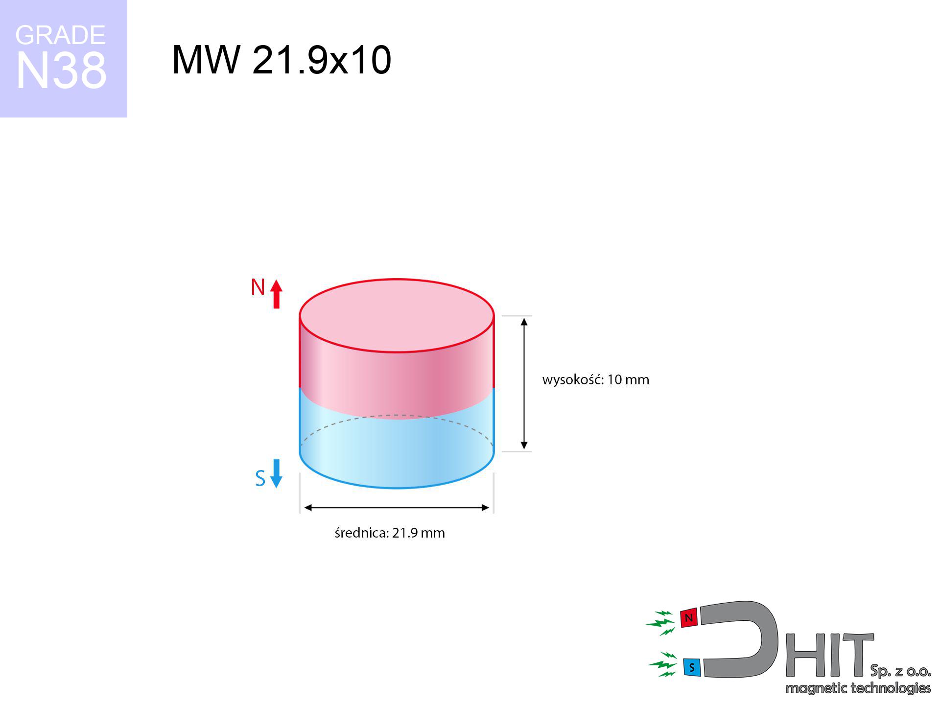
MW 21.9x10 / N38 - cylindrical magnet
cylindrical magnet
Catalog no 010045
GTIN/EAN: 5906301810445
Diameter Ø
21.9 mm [±0,1 mm]
Height
10 mm [±0,1 mm]
Weight
28.25 g
Magnetization Direction
→ diametrical
Load capacity
14.65 kg / 143.71 N
Magnetic Induction
417.89 mT / 4179 Gs
Coating
[NiCuNi] Nickel
15.50 ZŁ with VAT / pcs + price for transport
12.60 ZŁ net + 23% VAT / pcs
bulk discounts:
Need more?
Give us a call
+48 22 499 98 98
otherwise let us know through
request form
through our site.
Weight along with structure of magnets can be tested using our
force calculator.
Order by 14:00 and we’ll ship today!
Technical of the product - MW 21.9x10 / N38 - cylindrical magnet
Specification / characteristics - MW 21.9x10 / N38 - cylindrical magnet
| properties | values |
|---|---|
| Cat. no. | 010045 |
| GTIN/EAN | 5906301810445 |
| Production/Distribution | Dhit sp. z o.o. |
| Country of origin | Poland / China / Germany |
| Customs code | 85059029 |
| Diameter Ø | 21.9 mm [±0,1 mm] |
| Height | 10 mm [±0,1 mm] |
| Weight | 28.25 g |
| Magnetization Direction | → diametrical |
| Load capacity ~ ? | 14.65 kg / 143.71 N |
| Magnetic Induction ~ ? | 417.89 mT / 4179 Gs |
| Coating | [NiCuNi] Nickel |
| Manufacturing Tolerance | ±0.1 mm |
Magnetic properties of material N38
| properties | values | units |
|---|---|---|
| remenance Br [min. - max.] ? | 12.2-12.6 | kGs |
| remenance Br [min. - max.] ? | 1220-1260 | mT |
| coercivity bHc ? | 10.8-11.5 | kOe |
| coercivity bHc ? | 860-915 | kA/m |
| actual internal force iHc | ≥ 12 | kOe |
| actual internal force iHc | ≥ 955 | kA/m |
| energy density [min. - max.] ? | 36-38 | BH max MGOe |
| energy density [min. - max.] ? | 287-303 | BH max KJ/m |
| max. temperature ? | ≤ 80 | °C |
Physical properties of sintered neodymium magnets Nd2Fe14B at 20°C
| properties | values | units |
|---|---|---|
| Vickers hardness | ≥550 | Hv |
| Density | ≥7.4 | g/cm3 |
| Curie Temperature TC | 312 - 380 | °C |
| Curie Temperature TF | 593 - 716 | °F |
| Specific resistance | 150 | μΩ⋅cm |
| Bending strength | 250 | MPa |
| Compressive strength | 1000~1100 | MPa |
| Thermal expansion parallel (∥) to orientation (M) | (3-4) x 10-6 | °C-1 |
| Thermal expansion perpendicular (⊥) to orientation (M) | -(1-3) x 10-6 | °C-1 |
| Young's modulus | 1.7 x 10⁴ | kg/mm² |
Physical analysis of the assembly - data
The following data constitute the outcome of a physical analysis. Values rely on models for the material Nd2Fe14B. Real-world conditions may differ. Use these data as a reference point during assembly planning.
Table 1: Static force (pull vs distance) - power drop
MW 21.9x10 / N38
| Distance (mm) | Induction (Gauss) / mT | Pull Force (kg/lbs/g/N) | Risk Status |
|---|---|---|---|
| 0 mm |
4178 Gs
417.8 mT
|
14.65 kg / 32.30 LBS
14650.0 g / 143.7 N
|
dangerous! |
| 1 mm |
3830 Gs
383.0 mT
|
12.31 kg / 27.15 LBS
12314.7 g / 120.8 N
|
dangerous! |
| 2 mm |
3466 Gs
346.6 mT
|
10.08 kg / 22.23 LBS
10083.5 g / 98.9 N
|
dangerous! |
| 3 mm |
3104 Gs
310.4 mT
|
8.09 kg / 17.83 LBS
8086.3 g / 79.3 N
|
strong |
| 5 mm |
2432 Gs
243.2 mT
|
4.97 kg / 10.95 LBS
4966.5 g / 48.7 N
|
strong |
| 10 mm |
1257 Gs
125.7 mT
|
1.33 kg / 2.93 LBS
1327.0 g / 13.0 N
|
low risk |
| 15 mm |
671 Gs
67.1 mT
|
0.38 kg / 0.83 LBS
378.5 g / 3.7 N
|
low risk |
| 20 mm |
386 Gs
38.6 mT
|
0.13 kg / 0.28 LBS
125.0 g / 1.2 N
|
low risk |
| 30 mm |
156 Gs
15.6 mT
|
0.02 kg / 0.04 LBS
20.4 g / 0.2 N
|
low risk |
| 50 mm |
43 Gs
4.3 mT
|
0.00 kg / 0.00 LBS
1.5 g / 0.0 N
|
low risk |
Table 2: Shear load (wall)
MW 21.9x10 / N38
| Distance (mm) | Friction coefficient | Pull Force (kg/lbs/g/N) |
|---|---|---|
| 0 mm | Stal (~0.2) |
2.93 kg / 6.46 LBS
2930.0 g / 28.7 N
|
| 1 mm | Stal (~0.2) |
2.46 kg / 5.43 LBS
2462.0 g / 24.2 N
|
| 2 mm | Stal (~0.2) |
2.02 kg / 4.44 LBS
2016.0 g / 19.8 N
|
| 3 mm | Stal (~0.2) |
1.62 kg / 3.57 LBS
1618.0 g / 15.9 N
|
| 5 mm | Stal (~0.2) |
0.99 kg / 2.19 LBS
994.0 g / 9.8 N
|
| 10 mm | Stal (~0.2) |
0.27 kg / 0.59 LBS
266.0 g / 2.6 N
|
| 15 mm | Stal (~0.2) |
0.08 kg / 0.17 LBS
76.0 g / 0.7 N
|
| 20 mm | Stal (~0.2) |
0.03 kg / 0.06 LBS
26.0 g / 0.3 N
|
| 30 mm | Stal (~0.2) |
0.00 kg / 0.01 LBS
4.0 g / 0.0 N
|
| 50 mm | Stal (~0.2) |
0.00 kg / 0.00 LBS
0.0 g / 0.0 N
|
Table 3: Vertical assembly (sliding) - behavior on slippery surfaces
MW 21.9x10 / N38
| Surface type | Friction coefficient / % Mocy | Max load (kg/lbs/g/N) |
|---|---|---|
| Raw steel |
µ = 0.3
30% Nominalnej Siły
|
4.40 kg / 9.69 LBS
4395.0 g / 43.1 N
|
| Painted steel (standard) |
µ = 0.2
20% Nominalnej Siły
|
2.93 kg / 6.46 LBS
2930.0 g / 28.7 N
|
| Oily/slippery steel |
µ = 0.1
10% Nominalnej Siły
|
1.47 kg / 3.23 LBS
1465.0 g / 14.4 N
|
| Magnet with anti-slip rubber |
µ = 0.5
50% Nominalnej Siły
|
7.33 kg / 16.15 LBS
7325.0 g / 71.9 N
|
Table 4: Material efficiency (saturation) - sheet metal selection
MW 21.9x10 / N38
| Steel thickness (mm) | % power | Real pull force (kg/lbs/g/N) |
|---|---|---|
| 0.5 mm |
|
0.73 kg / 1.61 LBS
732.5 g / 7.2 N
|
| 1 mm |
|
1.83 kg / 4.04 LBS
1831.3 g / 18.0 N
|
| 2 mm |
|
3.66 kg / 8.07 LBS
3662.5 g / 35.9 N
|
| 3 mm |
|
5.49 kg / 12.11 LBS
5493.8 g / 53.9 N
|
| 5 mm |
|
9.16 kg / 20.19 LBS
9156.3 g / 89.8 N
|
| 10 mm |
|
14.65 kg / 32.30 LBS
14650.0 g / 143.7 N
|
| 11 mm |
|
14.65 kg / 32.30 LBS
14650.0 g / 143.7 N
|
| 12 mm |
|
14.65 kg / 32.30 LBS
14650.0 g / 143.7 N
|
Table 5: Thermal stability (material behavior) - power drop
MW 21.9x10 / N38
| Ambient temp. (°C) | Power loss | Remaining pull (kg/lbs/g/N) | Status |
|---|---|---|---|
| 20 °C | 0.0% |
14.65 kg / 32.30 LBS
14650.0 g / 143.7 N
|
OK |
| 40 °C | -2.2% |
14.33 kg / 31.59 LBS
14327.7 g / 140.6 N
|
OK |
| 60 °C | -4.4% |
14.01 kg / 30.88 LBS
14005.4 g / 137.4 N
|
|
| 80 °C | -6.6% |
13.68 kg / 30.17 LBS
13683.1 g / 134.2 N
|
|
| 100 °C | -28.8% |
10.43 kg / 23.00 LBS
10430.8 g / 102.3 N
|
Table 6: Magnet-Magnet interaction (attraction) - field collision
MW 21.9x10 / N38
| Gap (mm) | Attraction (kg/lbs) (N-S) | Sliding Force (kg/lbs/g/N) | Repulsion (kg/lbs) (N-N) |
|---|---|---|---|
| 0 mm |
40.53 kg / 89.35 LBS
5 433 Gs
|
6.08 kg / 13.40 LBS
6079 g / 59.6 N
|
N/A |
| 1 mm |
37.31 kg / 82.26 LBS
8 017 Gs
|
5.60 kg / 12.34 LBS
5597 g / 54.9 N
|
33.58 kg / 74.03 LBS
~0 Gs
|
| 2 mm |
34.07 kg / 75.11 LBS
7 660 Gs
|
5.11 kg / 11.27 LBS
5110 g / 50.1 N
|
30.66 kg / 67.60 LBS
~0 Gs
|
| 3 mm |
30.92 kg / 68.16 LBS
7 297 Gs
|
4.64 kg / 10.22 LBS
4637 g / 45.5 N
|
27.82 kg / 61.34 LBS
~0 Gs
|
| 5 mm |
25.04 kg / 55.20 LBS
6 567 Gs
|
3.76 kg / 8.28 LBS
3756 g / 36.8 N
|
22.54 kg / 49.68 LBS
~0 Gs
|
| 10 mm |
13.74 kg / 30.29 LBS
4 865 Gs
|
2.06 kg / 4.54 LBS
2061 g / 20.2 N
|
12.37 kg / 27.26 LBS
~0 Gs
|
| 20 mm |
3.67 kg / 8.09 LBS
2 515 Gs
|
0.55 kg / 1.21 LBS
551 g / 5.4 N
|
3.30 kg / 7.28 LBS
~0 Gs
|
| 50 mm |
0.13 kg / 0.29 LBS
476 Gs
|
0.02 kg / 0.04 LBS
20 g / 0.2 N
|
0.12 kg / 0.26 LBS
~0 Gs
|
| 60 mm |
0.06 kg / 0.12 LBS
312 Gs
|
0.01 kg / 0.02 LBS
8 g / 0.1 N
|
0.05 kg / 0.11 LBS
~0 Gs
|
| 70 mm |
0.03 kg / 0.06 LBS
214 Gs
|
0.00 kg / 0.01 LBS
4 g / 0.0 N
|
0.02 kg / 0.05 LBS
~0 Gs
|
| 80 mm |
0.01 kg / 0.03 LBS
153 Gs
|
0.00 kg / 0.00 LBS
2 g / 0.0 N
|
0.01 kg / 0.03 LBS
~0 Gs
|
| 90 mm |
0.01 kg / 0.02 LBS
113 Gs
|
0.00 kg / 0.00 LBS
1 g / 0.0 N
|
0.00 kg / 0.00 LBS
~0 Gs
|
| 100 mm |
0.00 kg / 0.01 LBS
86 Gs
|
0.00 kg / 0.00 LBS
1 g / 0.0 N
|
0.00 kg / 0.00 LBS
~0 Gs
|
Table 7: Safety (HSE) (electronics) - precautionary measures
MW 21.9x10 / N38
| Object / Device | Limit (Gauss) / mT | Safe distance |
|---|---|---|
| Pacemaker | 5 Gs (0.5 mT) | 11.0 cm |
| Hearing aid | 10 Gs (1.0 mT) | 9.0 cm |
| Timepiece | 20 Gs (2.0 mT) | 7.0 cm |
| Phone / Smartphone | 40 Gs (4.0 mT) | 5.5 cm |
| Car key | 50 Gs (5.0 mT) | 5.0 cm |
| Payment card | 400 Gs (40.0 mT) | 2.0 cm |
| HDD hard drive | 600 Gs (60.0 mT) | 2.0 cm |
Table 8: Collisions (kinetic energy) - collision effects
MW 21.9x10 / N38
| Start from (mm) | Speed (km/h) | Energy (J) | Predicted outcome |
|---|---|---|---|
| 10 mm |
24.23 km/h
(6.73 m/s)
|
0.64 J | |
| 30 mm |
39.81 km/h
(11.06 m/s)
|
1.73 J | |
| 50 mm |
51.36 km/h
(14.27 m/s)
|
2.87 J | |
| 100 mm |
72.63 km/h
(20.17 m/s)
|
5.75 J |
Table 9: Anti-corrosion coating durability
MW 21.9x10 / N38
| Technical parameter | Value / Description |
|---|---|
| Coating type | [NiCuNi] Nickel |
| Layer structure | Nickel - Copper - Nickel |
| Layer thickness | 10-20 µm |
| Salt spray test (SST) ? | 24 h |
| Recommended environment | Indoors only (dry) |
Table 10: Construction data (Flux)
MW 21.9x10 / N38
| Parameter | Value | SI Unit / Description |
|---|---|---|
| Magnetic Flux | 16 059 Mx | 160.6 µWb |
| Pc Coefficient | 0.55 | Low (Flat) |
Table 11: Submerged application
MW 21.9x10 / N38
| Environment | Effective steel pull | Effect |
|---|---|---|
| Air (land) | 14.65 kg | Standard |
| Water (riverbed) |
16.77 kg
(+2.12 kg buoyancy gain)
|
+14.5% |
1. Shear force
*Note: On a vertical wall, the magnet holds merely approx. 20-30% of its nominal pull.
2. Plate thickness effect
*Thin metal sheet (e.g. computer case) drastically weakens the holding force.
3. Heat tolerance
*For N38 grade, the critical limit is 80°C.
4. Demagnetization curve and operating point (B-H)
chart generated for the permeance coefficient Pc (Permeance Coefficient) = 0.55
The chart above illustrates the magnetic characteristics of the material within the second quadrant of the hysteresis loop. The solid red line represents the demagnetization curve (material potential), while the dashed blue line is the load line based on the magnet's geometry. The Pc (Permeance Coefficient), also known as the load line slope, is a dimensionless value that describes the relationship between the magnet's shape and its magnetic stability. The intersection of these two lines (the black dot) is the operating point — it determines the actual magnetic flux density generated by the magnet in this specific configuration. A higher Pc value means the magnet is more 'slender' (tall relative to its area), resulting in a higher operating point and better resistance to irreversible demagnetization caused by external fields or temperature. A value of 0.42 is relatively low (typical for flat magnets), meaning the operating point is closer to the 'knee' of the curve — caution is advised when operating at temperatures near the maximum limit to avoid strength loss.
Chemical composition
| iron (Fe) | 64% – 68% |
| neodymium (Nd) | 29% – 32% |
| boron (B) | 1.1% – 1.2% |
| dysprosium (Dy) | 0.5% – 2.0% |
| coating (Ni-Cu-Ni) | < 0.05% |
Ecology and recycling (GPSR)
| recyclability (EoL) | 100% |
| recycled raw materials | ~10% (pre-cons) |
| carbon footprint | low / zredukowany |
| waste code (EWC) | 16 02 16 |
Other deals


![MPL 40x10x4x2[7/3.5] / N38 - lamellar magnet](https://cdn3.dhit.pl/graphics/products/mpl40x10x4x27-3.5-suw.jpg "MPL 40x10x4x2[7/3.5] / N38 - lamellar magnet")
Strengths and weaknesses of neodymium magnets.
Pros
- They retain magnetic properties for almost 10 years – the loss is just ~1% (based on simulations),
- They do not lose their magnetic properties even under strong external field,
- By covering with a lustrous layer of nickel, the element has an aesthetic look,
- They show high magnetic induction at the operating surface, which affects their effectiveness,
- Made from properly selected components, these magnets show impressive resistance to high heat, enabling them to function (depending on their shape) at temperatures up to 230°C and above...
- Thanks to flexibility in shaping and the capacity to customize to client solutions,
- Universal use in innovative solutions – they are commonly used in HDD drives, electric motors, medical equipment, and modern systems.
- Relatively small size with high pulling force – neodymium magnets offer high power in small dimensions, which allows their use in miniature devices
Limitations
- They are fragile upon heavy impacts. To avoid cracks, it is worth securing magnets in a protective case. Such protection not only shields the magnet but also improves its resistance to damage
- Neodymium magnets lose their force under the influence of heating. As soon as 80°C is exceeded, many of them start losing their power. Therefore, we recommend our special magnets marked [AH], which maintain durability even at temperatures up to 230°C
- When exposed to humidity, magnets start to rust. To use them in conditions outside, it is recommended to use protective magnets, such as those in rubber or plastics, which secure oxidation and corrosion.
- Limited possibility of making nuts in the magnet and complex shapes - preferred is casing - mounting mechanism.
- Health risk resulting from small fragments of magnets are risky, if swallowed, which is particularly important in the aspect of protecting the youngest. It is also worth noting that tiny parts of these products are able to be problematic in diagnostics medical when they are in the body.
- Due to neodymium price, their price is relatively high,
Pull force analysis
Breakaway strength of the magnet in ideal conditions – what contributes to it?
- using a plate made of low-carbon steel, serving as a ideal flux conductor
- with a thickness minimum 10 mm
- characterized by even structure
- without any clearance between the magnet and steel
- during pulling in a direction perpendicular to the plane
- in neutral thermal conditions
Key elements affecting lifting force
- Distance (between the magnet and the plate), because even a microscopic clearance (e.g. 0.5 mm) can cause a reduction in lifting capacity by up to 50% (this also applies to varnish, rust or dirt).
- Force direction – remember that the magnet has greatest strength perpendicularly. Under sliding down, the capacity drops drastically, often to levels of 20-30% of the nominal value.
- Plate thickness – insufficiently thick sheet does not accept the full field, causing part of the power to be lost to the other side.
- Steel type – low-carbon steel gives the best results. Alloy steels lower magnetic permeability and holding force.
- Smoothness – full contact is obtained only on polished steel. Rough texture create air cushions, weakening the magnet.
- Thermal factor – hot environment reduces magnetic field. Exceeding the limit temperature can permanently damage the magnet.
Lifting capacity testing was conducted on a smooth plate of optimal thickness, under a perpendicular pulling force, however under shearing force the load capacity is reduced by as much as 5 times. In addition, even a slight gap between the magnet and the plate lowers the holding force.
Safety rules for work with neodymium magnets
Nickel coating and allergies
Nickel alert: The Ni-Cu-Ni coating contains nickel. If an allergic reaction happens, cease handling magnets and use protective gear.
GPS and phone interference
GPS units and mobile phones are highly susceptible to magnetic fields. Close proximity with a strong magnet can ruin the sensors in your phone.
Handling rules
Handle with care. Rare earth magnets attract from a distance and snap with massive power, often faster than you can move away.
Choking Hazard
Neodymium magnets are not suitable for play. Eating multiple magnets can lead to them pinching intestinal walls, which poses a direct threat to life and requires urgent medical intervention.
Heat warning
Avoid heat. Neodymium magnets are susceptible to heat. If you need operation above 80°C, inquire about special high-temperature series (H, SH, UH).
Pacemakers
Warning for patients: Strong magnetic fields affect electronics. Keep minimum 30 cm distance or ask another person to work with the magnets.
Data carriers
Very strong magnetic fields can corrupt files on credit cards, HDDs, and storage devices. Keep a distance of min. 10 cm.
Crushing force
Large magnets can smash fingers instantly. Do not put your hand betwixt two attracting surfaces.
Fragile material
Despite metallic appearance, the material is brittle and not impact-resistant. Avoid impacts, as the magnet may crumble into hazardous fragments.
Dust is flammable
Powder produced during cutting of magnets is flammable. Avoid drilling into magnets without proper cooling and knowledge.
Tabela kosztu i czasu dostawy
Płatność przed wysyłką:

GLS kurier
Przesyłka będzie u Ciebie za 2-3 dni
14.99 ZŁ

InPost Paczkomaty 24/7
Przesyłka będzie u Ciebie za 1-2 dni
12.30 ZŁ
Płatność przy odbiorze (pobranie):
GLS kurier
Przesyłka będzie u Ciebie za 1-2 dni
23.00 ZŁ
Rate the product
Your rating