
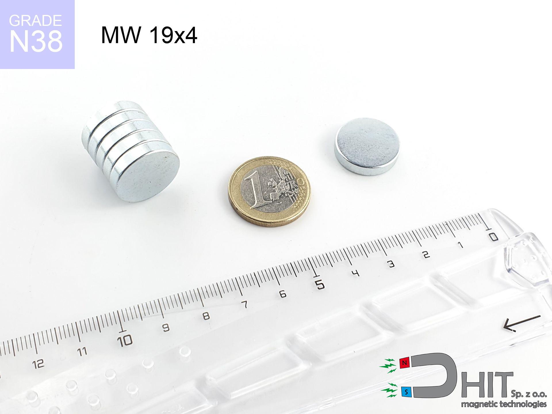
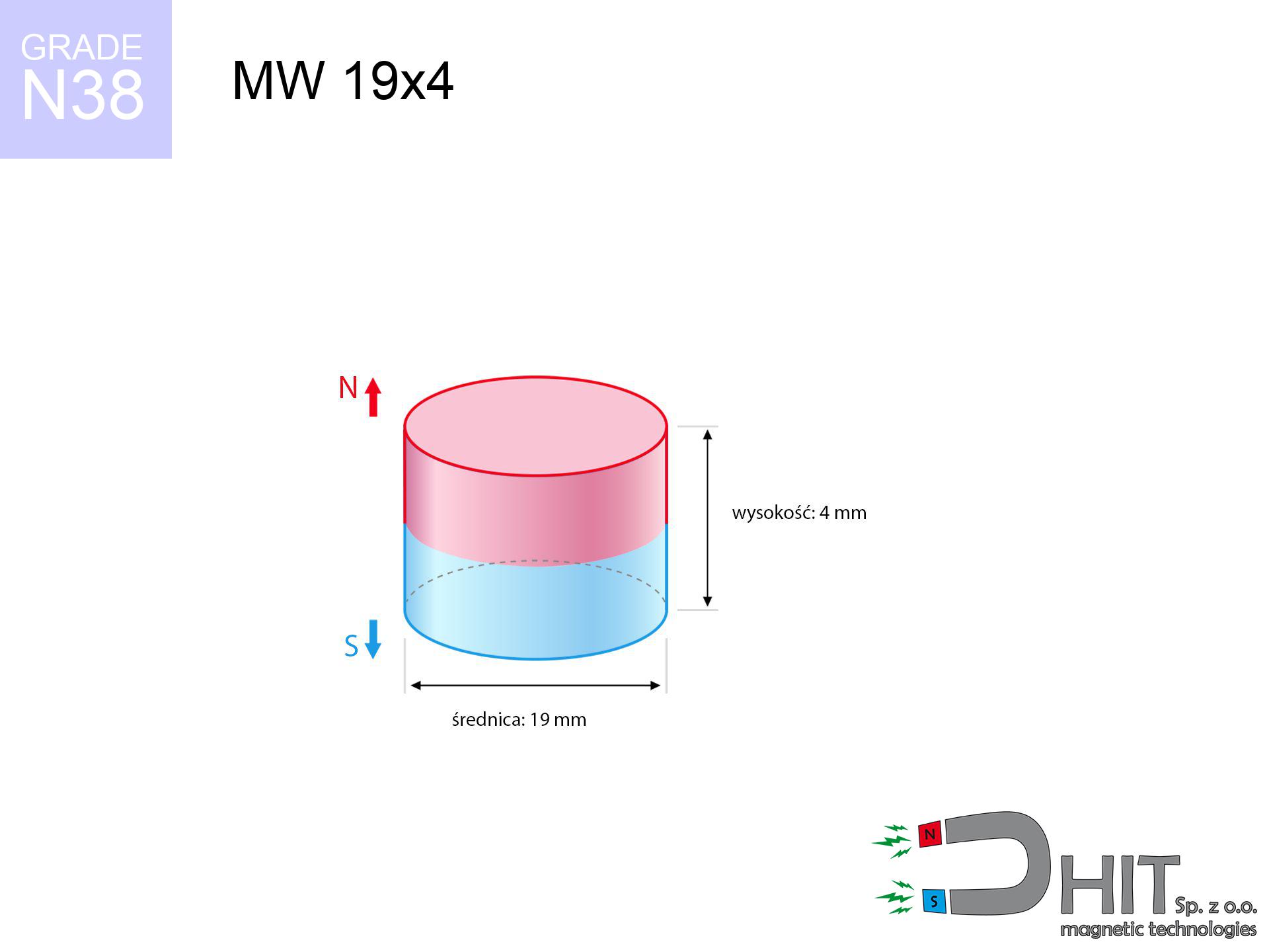
MW 19x4 / N38 - cylindrical magnet
cylindrical magnet
Catalog no 010038
GTIN/EAN: 5906301810377
Diameter Ø
19 mm [±0,1 mm]
Height
4 mm [±0,1 mm]
Weight
8.51 g
Magnetization Direction
↑ axial
Load capacity
4.96 kg / 48.62 N
Magnetic Induction
240.51 mT / 2405 Gs
Coating
[Zn] Zinc
4.80 ZŁ with VAT / pcs + price for transport
3.90 ZŁ net + 23% VAT / pcs
bulk discounts:
Need more?
Pick up the phone and ask
+48 888 99 98 98
alternatively drop us a message by means of
form
the contact form page.
Weight along with form of magnets can be analyzed using our
magnetic calculator.
Same-day shipping for orders placed before 14:00.
Technical of the product - MW 19x4 / N38 - cylindrical magnet
Specification / characteristics - MW 19x4 / N38 - cylindrical magnet
| properties | values |
|---|---|
| Cat. no. | 010038 |
| GTIN/EAN | 5906301810377 |
| Production/Distribution | Dhit sp. z o.o. |
| Country of origin | Poland / China / Germany |
| Customs code | 85059029 |
| Diameter Ø | 19 mm [±0,1 mm] |
| Height | 4 mm [±0,1 mm] |
| Weight | 8.51 g |
| Magnetization Direction | ↑ axial |
| Load capacity ~ ? | 4.96 kg / 48.62 N |
| Magnetic Induction ~ ? | 240.51 mT / 2405 Gs |
| Coating | [Zn] Zinc |
| Manufacturing Tolerance | ±0.1 mm |
Magnetic properties of material N38
| properties | values | units |
|---|---|---|
| remenance Br [min. - max.] ? | 12.2-12.6 | kGs |
| remenance Br [min. - max.] ? | 1220-1260 | mT |
| coercivity bHc ? | 10.8-11.5 | kOe |
| coercivity bHc ? | 860-915 | kA/m |
| actual internal force iHc | ≥ 12 | kOe |
| actual internal force iHc | ≥ 955 | kA/m |
| energy density [min. - max.] ? | 36-38 | BH max MGOe |
| energy density [min. - max.] ? | 287-303 | BH max KJ/m |
| max. temperature ? | ≤ 80 | °C |
Physical properties of sintered neodymium magnets Nd2Fe14B at 20°C
| properties | values | units |
|---|---|---|
| Vickers hardness | ≥550 | Hv |
| Density | ≥7.4 | g/cm3 |
| Curie Temperature TC | 312 - 380 | °C |
| Curie Temperature TF | 593 - 716 | °F |
| Specific resistance | 150 | μΩ⋅cm |
| Bending strength | 250 | MPa |
| Compressive strength | 1000~1100 | MPa |
| Thermal expansion parallel (∥) to orientation (M) | (3-4) x 10-6 | °C-1 |
| Thermal expansion perpendicular (⊥) to orientation (M) | -(1-3) x 10-6 | °C-1 |
| Young's modulus | 1.7 x 10⁴ | kg/mm² |
Physical modeling of the product - data
Presented data are the direct effect of a physical analysis. Results rely on models for the class Nd2Fe14B. Operational performance may differ. Use these calculations as a preliminary roadmap when designing systems.
Table 1: Static force (pull vs gap) - power drop
MW 19x4 / N38
| Distance (mm) | Induction (Gauss) / mT | Pull Force (kg/lbs/g/N) | Risk Status |
|---|---|---|---|
| 0 mm |
2405 Gs
240.5 mT
|
4.96 kg / 10.93 pounds
4960.0 g / 48.7 N
|
warning |
| 1 mm |
2239 Gs
223.9 mT
|
4.30 kg / 9.48 pounds
4299.0 g / 42.2 N
|
warning |
| 2 mm |
2033 Gs
203.3 mT
|
3.55 kg / 7.82 pounds
3547.4 g / 34.8 N
|
warning |
| 3 mm |
1811 Gs
181.1 mT
|
2.81 kg / 6.20 pounds
2813.0 g / 27.6 N
|
warning |
| 5 mm |
1376 Gs
137.6 mT
|
1.63 kg / 3.58 pounds
1625.2 g / 15.9 N
|
weak grip |
| 10 mm |
635 Gs
63.5 mT
|
0.35 kg / 0.76 pounds
346.3 g / 3.4 N
|
weak grip |
| 15 mm |
308 Gs
30.8 mT
|
0.08 kg / 0.18 pounds
81.2 g / 0.8 N
|
weak grip |
| 20 mm |
164 Gs
16.4 mT
|
0.02 kg / 0.05 pounds
23.2 g / 0.2 N
|
weak grip |
| 30 mm |
61 Gs
6.1 mT
|
0.00 kg / 0.01 pounds
3.1 g / 0.0 N
|
weak grip |
| 50 mm |
15 Gs
1.5 mT
|
0.00 kg / 0.00 pounds
0.2 g / 0.0 N
|
weak grip |
Table 2: Slippage hold (wall)
MW 19x4 / N38
| Distance (mm) | Friction coefficient | Pull Force (kg/lbs/g/N) |
|---|---|---|
| 0 mm | Stal (~0.2) |
0.99 kg / 2.19 pounds
992.0 g / 9.7 N
|
| 1 mm | Stal (~0.2) |
0.86 kg / 1.90 pounds
860.0 g / 8.4 N
|
| 2 mm | Stal (~0.2) |
0.71 kg / 1.57 pounds
710.0 g / 7.0 N
|
| 3 mm | Stal (~0.2) |
0.56 kg / 1.24 pounds
562.0 g / 5.5 N
|
| 5 mm | Stal (~0.2) |
0.33 kg / 0.72 pounds
326.0 g / 3.2 N
|
| 10 mm | Stal (~0.2) |
0.07 kg / 0.15 pounds
70.0 g / 0.7 N
|
| 15 mm | Stal (~0.2) |
0.02 kg / 0.04 pounds
16.0 g / 0.2 N
|
| 20 mm | Stal (~0.2) |
0.00 kg / 0.01 pounds
4.0 g / 0.0 N
|
| 30 mm | Stal (~0.2) |
0.00 kg / 0.00 pounds
0.0 g / 0.0 N
|
| 50 mm | Stal (~0.2) |
0.00 kg / 0.00 pounds
0.0 g / 0.0 N
|
Table 3: Vertical assembly (shearing) - behavior on slippery surfaces
MW 19x4 / N38
| Surface type | Friction coefficient / % Mocy | Max load (kg/lbs/g/N) |
|---|---|---|
| Raw steel |
µ = 0.3
30% Nominalnej Siły
|
1.49 kg / 3.28 pounds
1488.0 g / 14.6 N
|
| Painted steel (standard) |
µ = 0.2
20% Nominalnej Siły
|
0.99 kg / 2.19 pounds
992.0 g / 9.7 N
|
| Oily/slippery steel |
µ = 0.1
10% Nominalnej Siły
|
0.50 kg / 1.09 pounds
496.0 g / 4.9 N
|
| Magnet with anti-slip rubber |
µ = 0.5
50% Nominalnej Siły
|
2.48 kg / 5.47 pounds
2480.0 g / 24.3 N
|
Table 4: Material efficiency (saturation) - sheet metal selection
MW 19x4 / N38
| Steel thickness (mm) | % power | Real pull force (kg/lbs/g/N) |
|---|---|---|
| 0.5 mm |
|
0.50 kg / 1.09 pounds
496.0 g / 4.9 N
|
| 1 mm |
|
1.24 kg / 2.73 pounds
1240.0 g / 12.2 N
|
| 2 mm |
|
2.48 kg / 5.47 pounds
2480.0 g / 24.3 N
|
| 3 mm |
|
3.72 kg / 8.20 pounds
3720.0 g / 36.5 N
|
| 5 mm |
|
4.96 kg / 10.93 pounds
4960.0 g / 48.7 N
|
| 10 mm |
|
4.96 kg / 10.93 pounds
4960.0 g / 48.7 N
|
| 11 mm |
|
4.96 kg / 10.93 pounds
4960.0 g / 48.7 N
|
| 12 mm |
|
4.96 kg / 10.93 pounds
4960.0 g / 48.7 N
|
Table 5: Thermal stability (stability) - power drop
MW 19x4 / N38
| Ambient temp. (°C) | Power loss | Remaining pull (kg/lbs/g/N) | Status |
|---|---|---|---|
| 20 °C | 0.0% |
4.96 kg / 10.93 pounds
4960.0 g / 48.7 N
|
OK |
| 40 °C | -2.2% |
4.85 kg / 10.69 pounds
4850.9 g / 47.6 N
|
OK |
| 60 °C | -4.4% |
4.74 kg / 10.45 pounds
4741.8 g / 46.5 N
|
|
| 80 °C | -6.6% |
4.63 kg / 10.21 pounds
4632.6 g / 45.4 N
|
|
| 100 °C | -28.8% |
3.53 kg / 7.79 pounds
3531.5 g / 34.6 N
|
Table 6: Magnet-Magnet interaction (attraction) - field collision
MW 19x4 / N38
| Gap (mm) | Attraction (kg/lbs) (N-S) | Lateral Force (kg/lbs/g/N) | Repulsion (kg/lbs) (N-N) |
|---|---|---|---|
| 0 mm |
10.11 kg / 22.28 pounds
3 990 Gs
|
1.52 kg / 3.34 pounds
1516 g / 14.9 N
|
N/A |
| 1 mm |
9.48 kg / 20.89 pounds
4 657 Gs
|
1.42 kg / 3.13 pounds
1421 g / 13.9 N
|
8.53 kg / 18.80 pounds
~0 Gs
|
| 2 mm |
8.76 kg / 19.31 pounds
4 477 Gs
|
1.31 kg / 2.90 pounds
1314 g / 12.9 N
|
7.88 kg / 17.38 pounds
~0 Gs
|
| 3 mm |
8.00 kg / 17.64 pounds
4 279 Gs
|
1.20 kg / 2.65 pounds
1200 g / 11.8 N
|
7.20 kg / 15.88 pounds
~0 Gs
|
| 5 mm |
6.47 kg / 14.25 pounds
3 846 Gs
|
0.97 kg / 2.14 pounds
970 g / 9.5 N
|
5.82 kg / 12.83 pounds
~0 Gs
|
| 10 mm |
3.31 kg / 7.30 pounds
2 753 Gs
|
0.50 kg / 1.10 pounds
497 g / 4.9 N
|
2.98 kg / 6.57 pounds
~0 Gs
|
| 20 mm |
0.71 kg / 1.56 pounds
1 271 Gs
|
0.11 kg / 0.23 pounds
106 g / 1.0 N
|
0.64 kg / 1.40 pounds
~0 Gs
|
| 50 mm |
0.02 kg / 0.04 pounds
193 Gs
|
0.00 kg / 0.01 pounds
2 g / 0.0 N
|
0.01 kg / 0.03 pounds
~0 Gs
|
| 60 mm |
0.01 kg / 0.01 pounds
121 Gs
|
0.00 kg / 0.00 pounds
1 g / 0.0 N
|
0.00 kg / 0.00 pounds
~0 Gs
|
| 70 mm |
0.00 kg / 0.01 pounds
81 Gs
|
0.00 kg / 0.00 pounds
0 g / 0.0 N
|
0.00 kg / 0.00 pounds
~0 Gs
|
| 80 mm |
0.00 kg / 0.00 pounds
56 Gs
|
0.00 kg / 0.00 pounds
0 g / 0.0 N
|
0.00 kg / 0.00 pounds
~0 Gs
|
| 90 mm |
0.00 kg / 0.00 pounds
41 Gs
|
0.00 kg / 0.00 pounds
0 g / 0.0 N
|
0.00 kg / 0.00 pounds
~0 Gs
|
| 100 mm |
0.00 kg / 0.00 pounds
30 Gs
|
0.00 kg / 0.00 pounds
0 g / 0.0 N
|
0.00 kg / 0.00 pounds
~0 Gs
|
Table 7: Protective zones (electronics) - warnings
MW 19x4 / N38
| Object / Device | Limit (Gauss) / mT | Safe distance |
|---|---|---|
| Pacemaker | 5 Gs (0.5 mT) | 7.5 cm |
| Hearing aid | 10 Gs (1.0 mT) | 6.0 cm |
| Timepiece | 20 Gs (2.0 mT) | 5.0 cm |
| Phone / Smartphone | 40 Gs (4.0 mT) | 4.0 cm |
| Car key | 50 Gs (5.0 mT) | 3.5 cm |
| Payment card | 400 Gs (40.0 mT) | 1.5 cm |
| HDD hard drive | 600 Gs (60.0 mT) | 1.5 cm |
Table 8: Impact energy (kinetic energy) - collision effects
MW 19x4 / N38
| Start from (mm) | Speed (km/h) | Energy (J) | Predicted outcome |
|---|---|---|---|
| 10 mm |
25.39 km/h
(7.05 m/s)
|
0.21 J | |
| 30 mm |
42.19 km/h
(11.72 m/s)
|
0.58 J | |
| 50 mm |
54.44 km/h
(15.12 m/s)
|
0.97 J | |
| 100 mm |
76.99 km/h
(21.39 m/s)
|
1.95 J |
Table 9: Anti-corrosion coating durability
MW 19x4 / N38
| Technical parameter | Value / Description |
|---|---|
| Coating type | [Zn] Zinc |
| Layer structure | Zn (Zinc) |
| Layer thickness | 8-15 µm |
| Salt spray test (SST) ? | 48 h |
| Recommended environment | Indoors / Garage |
Table 10: Electrical data (Pc)
MW 19x4 / N38
| Parameter | Value | SI Unit / Description |
|---|---|---|
| Magnetic Flux | 7 831 Mx | 78.3 µWb |
| Pc Coefficient | 0.30 | Low (Flat) |
Table 11: Underwater work (magnet fishing)
MW 19x4 / N38
| Environment | Effective steel pull | Effect |
|---|---|---|
| Air (land) | 4.96 kg | Standard |
| Water (riverbed) |
5.68 kg
(+0.72 kg buoyancy gain)
|
+14.5% |
1. Shear force
*Note: On a vertical wall, the magnet retains only ~20% of its perpendicular strength.
2. Efficiency vs thickness
*Thin steel (e.g. 0.5mm PC case) drastically reduces the holding force.
3. Thermal stability
*For N38 material, the safety limit is 80°C.
4. Demagnetization curve and operating point (B-H)
chart generated for the permeance coefficient Pc (Permeance Coefficient) = 0.30
The chart above illustrates the magnetic characteristics of the material within the second quadrant of the hysteresis loop. The solid red line represents the demagnetization curve (material potential), while the dashed blue line is the load line based on the magnet's geometry. The Pc (Permeance Coefficient), also known as the load line slope, is a dimensionless value that describes the relationship between the magnet's shape and its magnetic stability. The intersection of these two lines (the black dot) is the operating point — it determines the actual magnetic flux density generated by the magnet in this specific configuration. A higher Pc value means the magnet is more 'slender' (tall relative to its area), resulting in a higher operating point and better resistance to irreversible demagnetization caused by external fields or temperature. A value of 0.42 is relatively low (typical for flat magnets), meaning the operating point is closer to the 'knee' of the curve — caution is advised when operating at temperatures near the maximum limit to avoid strength loss.
Material specification
| iron (Fe) | 64% – 68% |
| neodymium (Nd) | 29% – 32% |
| boron (B) | 1.1% – 1.2% |
| dysprosium (Dy) | 0.5% – 2.0% |
| coating (Ni-Cu-Ni) | < 0.05% |
Environmental data
| recyclability (EoL) | 100% |
| recycled raw materials | ~10% (pre-cons) |
| carbon footprint | low / zredukowany |
| waste code (EWC) | 16 02 16 |
Other products

![SM 32x300 [2xM8] / N42 - magnetic separator](https://cdn3.dhit.pl/graphics/products/sm-32x300-2xm8-pel.jpg "SM 32x300 [2xM8] / N42 - magnetic separator")
![UMGW 42x20x9 [M6] GW / N38 - magnetic holder internal thread](https://cdn3.dhit.pl/graphics/products/um-42x20x9-m8-gw-god.jpg "UMGW 42x20x9 [M6] GW / N38 - magnetic holder internal thread")

Advantages and disadvantages of Nd2Fe14B magnets.
Advantages
- They retain magnetic properties for nearly 10 years – the loss is just ~1% (based on simulations),
- Neodymium magnets are highly resistant to demagnetization caused by external field sources,
- In other words, due to the reflective finish of gold, the element gains a professional look,
- The surface of neodymium magnets generates a intense magnetic field – this is a key feature,
- Through (appropriate) combination of ingredients, they can achieve high thermal resistance, enabling operation at temperatures reaching 230°C and above...
- Possibility of exact shaping and adjusting to individual conditions,
- Fundamental importance in future technologies – they find application in computer drives, electromotive mechanisms, medical equipment, also industrial machines.
- Relatively small size with high pulling force – neodymium magnets offer high power in small dimensions, which allows their use in miniature devices
Weaknesses
- Susceptibility to cracking is one of their disadvantages. Upon intense impact they can fracture. We recommend keeping them in a strong case, which not only protects them against impacts but also raises their durability
- We warn that neodymium magnets can lose their strength at high temperatures. To prevent this, we advise our specialized [AH] magnets, which work effectively even at 230°C.
- Due to the susceptibility of magnets to corrosion in a humid environment, we advise using waterproof magnets made of rubber, plastic or other material immune to moisture, in case of application outdoors
- We suggest cover - magnetic mechanism, due to difficulties in creating threads inside the magnet and complex shapes.
- Possible danger to health – tiny shards of magnets are risky, in case of ingestion, which becomes key in the aspect of protecting the youngest. Additionally, small components of these devices can be problematic in diagnostics medical after entering the body.
- High unit price – neodymium magnets cost more than other types of magnets (e.g. ferrite), which can limit application in large quantities
Pull force analysis
Breakaway strength of the magnet in ideal conditions – what affects it?
- with the application of a sheet made of low-carbon steel, guaranteeing maximum field concentration
- whose thickness is min. 10 mm
- with a surface free of scratches
- with direct contact (without impurities)
- for force acting at a right angle (pull-off, not shear)
- at conditions approx. 20°C
Lifting capacity in practice – influencing factors
- Gap (betwixt the magnet and the metal), because even a microscopic clearance (e.g. 0.5 mm) can cause a drastic drop in lifting capacity by up to 50% (this also applies to paint, corrosion or dirt).
- Loading method – declared lifting capacity refers to detachment vertically. When applying parallel force, the magnet holds much less (typically approx. 20-30% of maximum force).
- Steel thickness – insufficiently thick sheet does not accept the full field, causing part of the power to be escaped into the air.
- Steel grade – the best choice is pure iron steel. Stainless steels may attract less.
- Surface finish – ideal contact is possible only on smooth steel. Any scratches and bumps create air cushions, reducing force.
- Temperature influence – high temperature reduces pulling force. Too high temperature can permanently damage the magnet.
Lifting capacity was measured using a polished steel plate of optimal thickness (min. 20 mm), under perpendicular pulling force, however under shearing force the holding force is lower. Moreover, even a slight gap between the magnet and the plate lowers the load capacity.
Warnings
GPS and phone interference
GPS units and mobile phones are highly susceptible to magnetic fields. Close proximity with a strong magnet can ruin the internal compass in your phone.
Protect data
Do not bring magnets close to a purse, laptop, or TV. The magnetism can permanently damage these devices and wipe information from cards.
Medical interference
Warning for patients: Powerful magnets disrupt electronics. Keep minimum 30 cm distance or ask another person to work with the magnets.
Conscious usage
Before starting, check safety instructions. Sudden snapping can destroy the magnet or injure your hand. Be predictive.
Heat sensitivity
Watch the temperature. Exposing the magnet to high heat will destroy its properties and strength.
Warning for allergy sufferers
Medical facts indicate that nickel (standard magnet coating) is a strong allergen. If your skin reacts to metals, prevent touching magnets with bare hands and opt for encased magnets.
Dust is flammable
Fire hazard: Rare earth powder is highly flammable. Do not process magnets in home conditions as this risks ignition.
Crushing risk
Danger of trauma: The pulling power is so great that it can result in blood blisters, crushing, and broken bones. Use thick gloves.
Swallowing risk
Product intended for adults. Small elements pose a choking risk, causing severe trauma. Store away from kids and pets.
Shattering risk
Neodymium magnets are sintered ceramics, meaning they are prone to chipping. Clashing of two magnets leads to them breaking into small pieces.
Tabela kosztu i czasu dostawy
Płatność przed wysyłką:

GLS kurier
Przesyłka będzie u Ciebie za 2-3 dni
14.99 ZŁ

InPost Paczkomaty 24/7
Przesyłka będzie u Ciebie za 1-2 dni
12.30 ZŁ
Płatność przy odbiorze (pobranie):
GLS kurier
Przesyłka będzie u Ciebie za 1-2 dni
23.00 ZŁ
Rate the product
Your rating