
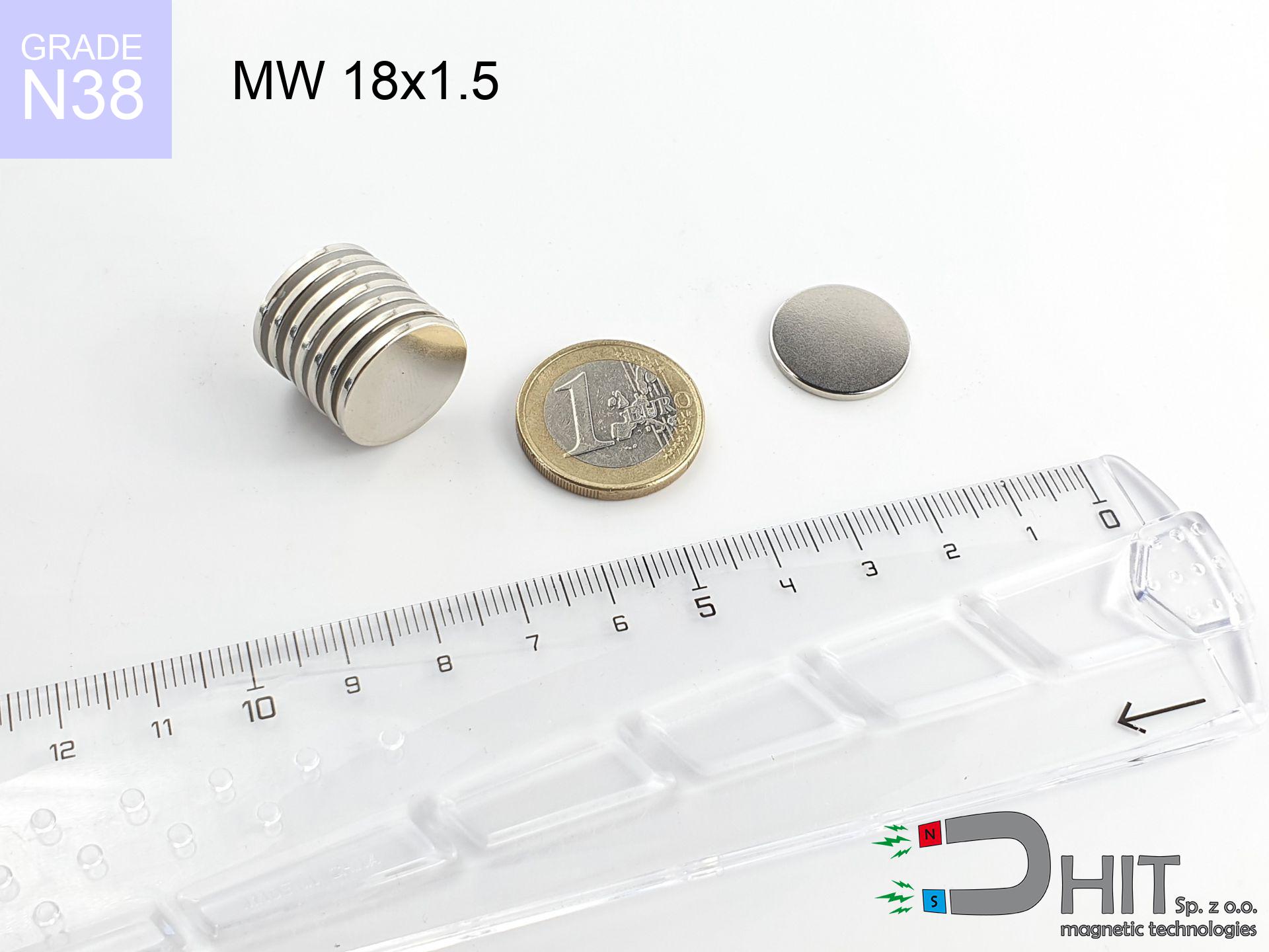
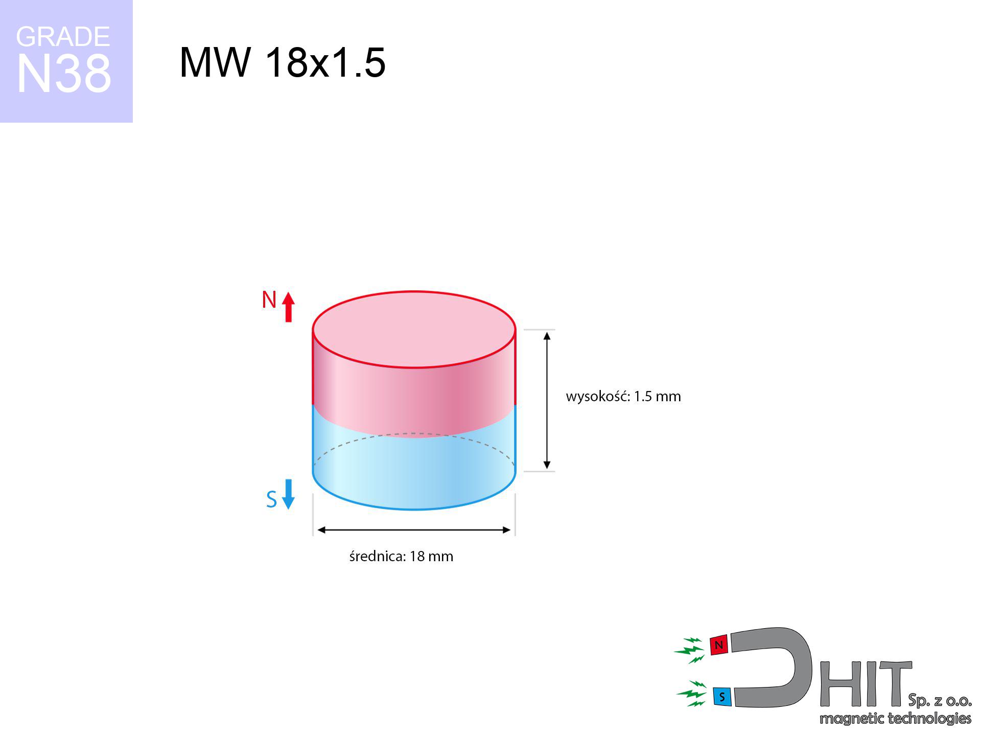
MW 18x1.5 / N38 - cylindrical magnet
cylindrical magnet
Catalog no 010037
GTIN/EAN: 5906301810360
Diameter Ø
18 mm [±0,1 mm]
Height
1.5 mm [±0,1 mm]
Weight
2.86 g
Magnetization Direction
↑ axial
Load capacity
0.95 kg / 9.34 N
Magnetic Induction
101.91 mT / 1019 Gs
Coating
[NiCuNi] Nickel
1.353 ZŁ with VAT / pcs + price for transport
1.100 ZŁ net + 23% VAT / pcs
bulk discounts:
Need more?
Contact us by phone
+48 22 499 98 98
alternatively drop us a message by means of
request form
our website.
Force and appearance of a neodymium magnet can be verified on our
our magnetic calculator.
Orders submitted before 14:00 will be dispatched today!
Technical details - MW 18x1.5 / N38 - cylindrical magnet
Specification / characteristics - MW 18x1.5 / N38 - cylindrical magnet
| properties | values |
|---|---|
| Cat. no. | 010037 |
| GTIN/EAN | 5906301810360 |
| Production/Distribution | Dhit sp. z o.o. |
| Country of origin | Poland / China / Germany |
| Customs code | 85059029 |
| Diameter Ø | 18 mm [±0,1 mm] |
| Height | 1.5 mm [±0,1 mm] |
| Weight | 2.86 g |
| Magnetization Direction | ↑ axial |
| Load capacity ~ ? | 0.95 kg / 9.34 N |
| Magnetic Induction ~ ? | 101.91 mT / 1019 Gs |
| Coating | [NiCuNi] Nickel |
| Manufacturing Tolerance | ±0.1 mm |
Magnetic properties of material N38
| properties | values | units |
|---|---|---|
| remenance Br [min. - max.] ? | 12.2-12.6 | kGs |
| remenance Br [min. - max.] ? | 1220-1260 | mT |
| coercivity bHc ? | 10.8-11.5 | kOe |
| coercivity bHc ? | 860-915 | kA/m |
| actual internal force iHc | ≥ 12 | kOe |
| actual internal force iHc | ≥ 955 | kA/m |
| energy density [min. - max.] ? | 36-38 | BH max MGOe |
| energy density [min. - max.] ? | 287-303 | BH max KJ/m |
| max. temperature ? | ≤ 80 | °C |
Physical properties of sintered neodymium magnets Nd2Fe14B at 20°C
| properties | values | units |
|---|---|---|
| Vickers hardness | ≥550 | Hv |
| Density | ≥7.4 | g/cm3 |
| Curie Temperature TC | 312 - 380 | °C |
| Curie Temperature TF | 593 - 716 | °F |
| Specific resistance | 150 | μΩ⋅cm |
| Bending strength | 250 | MPa |
| Compressive strength | 1000~1100 | MPa |
| Thermal expansion parallel (∥) to orientation (M) | (3-4) x 10-6 | °C-1 |
| Thermal expansion perpendicular (⊥) to orientation (M) | -(1-3) x 10-6 | °C-1 |
| Young's modulus | 1.7 x 10⁴ | kg/mm² |
Technical simulation of the product - report
The following data represent the result of a physical analysis. Results rely on algorithms for the class Nd2Fe14B. Actual performance might slightly deviate from the simulation results. Treat these data as a reference point for designers.
Table 1: Static pull force (force vs gap) - power drop
MW 18x1.5 / N38
| Distance (mm) | Induction (Gauss) / mT | Pull Force (kg/lbs/g/N) | Risk Status |
|---|---|---|---|
| 0 mm |
1019 Gs
101.9 mT
|
0.95 kg / 2.09 pounds
950.0 g / 9.3 N
|
safe |
| 1 mm |
975 Gs
97.5 mT
|
0.87 kg / 1.92 pounds
869.2 g / 8.5 N
|
safe |
| 2 mm |
902 Gs
90.2 mT
|
0.74 kg / 1.64 pounds
744.7 g / 7.3 N
|
safe |
| 3 mm |
812 Gs
81.2 mT
|
0.60 kg / 1.33 pounds
603.4 g / 5.9 N
|
safe |
| 5 mm |
619 Gs
61.9 mT
|
0.35 kg / 0.77 pounds
350.6 g / 3.4 N
|
safe |
| 10 mm |
274 Gs
27.4 mT
|
0.07 kg / 0.15 pounds
68.7 g / 0.7 N
|
safe |
| 15 mm |
126 Gs
12.6 mT
|
0.01 kg / 0.03 pounds
14.6 g / 0.1 N
|
safe |
| 20 mm |
65 Gs
6.5 mT
|
0.00 kg / 0.01 pounds
3.9 g / 0.0 N
|
safe |
| 30 mm |
23 Gs
2.3 mT
|
0.00 kg / 0.00 pounds
0.5 g / 0.0 N
|
safe |
| 50 mm |
6 Gs
0.6 mT
|
0.00 kg / 0.00 pounds
0.0 g / 0.0 N
|
safe |
Table 2: Vertical load (vertical surface)
MW 18x1.5 / N38
| Distance (mm) | Friction coefficient | Pull Force (kg/lbs/g/N) |
|---|---|---|
| 0 mm | Stal (~0.2) |
0.19 kg / 0.42 pounds
190.0 g / 1.9 N
|
| 1 mm | Stal (~0.2) |
0.17 kg / 0.38 pounds
174.0 g / 1.7 N
|
| 2 mm | Stal (~0.2) |
0.15 kg / 0.33 pounds
148.0 g / 1.5 N
|
| 3 mm | Stal (~0.2) |
0.12 kg / 0.26 pounds
120.0 g / 1.2 N
|
| 5 mm | Stal (~0.2) |
0.07 kg / 0.15 pounds
70.0 g / 0.7 N
|
| 10 mm | Stal (~0.2) |
0.01 kg / 0.03 pounds
14.0 g / 0.1 N
|
| 15 mm | Stal (~0.2) |
0.00 kg / 0.00 pounds
2.0 g / 0.0 N
|
| 20 mm | Stal (~0.2) |
0.00 kg / 0.00 pounds
0.0 g / 0.0 N
|
| 30 mm | Stal (~0.2) |
0.00 kg / 0.00 pounds
0.0 g / 0.0 N
|
| 50 mm | Stal (~0.2) |
0.00 kg / 0.00 pounds
0.0 g / 0.0 N
|
Table 3: Vertical assembly (shearing) - behavior on slippery surfaces
MW 18x1.5 / N38
| Surface type | Friction coefficient / % Mocy | Max load (kg/lbs/g/N) |
|---|---|---|
| Raw steel |
µ = 0.3
30% Nominalnej Siły
|
0.29 kg / 0.63 pounds
285.0 g / 2.8 N
|
| Painted steel (standard) |
µ = 0.2
20% Nominalnej Siły
|
0.19 kg / 0.42 pounds
190.0 g / 1.9 N
|
| Oily/slippery steel |
µ = 0.1
10% Nominalnej Siły
|
0.10 kg / 0.21 pounds
95.0 g / 0.9 N
|
| Magnet with anti-slip rubber |
µ = 0.5
50% Nominalnej Siły
|
0.48 kg / 1.05 pounds
475.0 g / 4.7 N
|
Table 4: Material efficiency (substrate influence) - power losses
MW 18x1.5 / N38
| Steel thickness (mm) | % power | Real pull force (kg/lbs/g/N) |
|---|---|---|
| 0.5 mm |
|
0.10 kg / 0.21 pounds
95.0 g / 0.9 N
|
| 1 mm |
|
0.24 kg / 0.52 pounds
237.5 g / 2.3 N
|
| 2 mm |
|
0.48 kg / 1.05 pounds
475.0 g / 4.7 N
|
| 3 mm |
|
0.71 kg / 1.57 pounds
712.5 g / 7.0 N
|
| 5 mm |
|
0.95 kg / 2.09 pounds
950.0 g / 9.3 N
|
| 10 mm |
|
0.95 kg / 2.09 pounds
950.0 g / 9.3 N
|
| 11 mm |
|
0.95 kg / 2.09 pounds
950.0 g / 9.3 N
|
| 12 mm |
|
0.95 kg / 2.09 pounds
950.0 g / 9.3 N
|
Table 5: Thermal stability (stability) - thermal limit
MW 18x1.5 / N38
| Ambient temp. (°C) | Power loss | Remaining pull (kg/lbs/g/N) | Status |
|---|---|---|---|
| 20 °C | 0.0% |
0.95 kg / 2.09 pounds
950.0 g / 9.3 N
|
OK |
| 40 °C | -2.2% |
0.93 kg / 2.05 pounds
929.1 g / 9.1 N
|
OK |
| 60 °C | -4.4% |
0.91 kg / 2.00 pounds
908.2 g / 8.9 N
|
|
| 80 °C | -6.6% |
0.89 kg / 1.96 pounds
887.3 g / 8.7 N
|
|
| 100 °C | -28.8% |
0.68 kg / 1.49 pounds
676.4 g / 6.6 N
|
Table 6: Two magnets (attraction) - field range
MW 18x1.5 / N38
| Gap (mm) | Attraction (kg/lbs) (N-S) | Shear Force (kg/lbs/g/N) | Repulsion (kg/lbs) (N-N) |
|---|---|---|---|
| 0 mm |
1.63 kg / 3.59 pounds
1 960 Gs
|
0.24 kg / 0.54 pounds
244 g / 2.4 N
|
N/A |
| 1 mm |
1.57 kg / 3.47 pounds
2 002 Gs
|
0.24 kg / 0.52 pounds
236 g / 2.3 N
|
1.41 kg / 3.12 pounds
~0 Gs
|
| 2 mm |
1.49 kg / 3.29 pounds
1 949 Gs
|
0.22 kg / 0.49 pounds
224 g / 2.2 N
|
1.34 kg / 2.96 pounds
~0 Gs
|
| 3 mm |
1.39 kg / 3.06 pounds
1 883 Gs
|
0.21 kg / 0.46 pounds
209 g / 2.0 N
|
1.25 kg / 2.76 pounds
~0 Gs
|
| 5 mm |
1.16 kg / 2.55 pounds
1 717 Gs
|
0.17 kg / 0.38 pounds
174 g / 1.7 N
|
1.04 kg / 2.30 pounds
~0 Gs
|
| 10 mm |
0.60 kg / 1.33 pounds
1 238 Gs
|
0.09 kg / 0.20 pounds
90 g / 0.9 N
|
0.54 kg / 1.19 pounds
~0 Gs
|
| 20 mm |
0.12 kg / 0.26 pounds
548 Gs
|
0.02 kg / 0.04 pounds
18 g / 0.2 N
|
0.11 kg / 0.23 pounds
~0 Gs
|
| 50 mm |
0.00 kg / 0.00 pounds
74 Gs
|
0.00 kg / 0.00 pounds
0 g / 0.0 N
|
0.00 kg / 0.00 pounds
~0 Gs
|
| 60 mm |
0.00 kg / 0.00 pounds
46 Gs
|
0.00 kg / 0.00 pounds
0 g / 0.0 N
|
0.00 kg / 0.00 pounds
~0 Gs
|
| 70 mm |
0.00 kg / 0.00 pounds
30 Gs
|
0.00 kg / 0.00 pounds
0 g / 0.0 N
|
0.00 kg / 0.00 pounds
~0 Gs
|
| 80 mm |
0.00 kg / 0.00 pounds
21 Gs
|
0.00 kg / 0.00 pounds
0 g / 0.0 N
|
0.00 kg / 0.00 pounds
~0 Gs
|
| 90 mm |
0.00 kg / 0.00 pounds
15 Gs
|
0.00 kg / 0.00 pounds
0 g / 0.0 N
|
0.00 kg / 0.00 pounds
~0 Gs
|
| 100 mm |
0.00 kg / 0.00 pounds
11 Gs
|
0.00 kg / 0.00 pounds
0 g / 0.0 N
|
0.00 kg / 0.00 pounds
~0 Gs
|
Table 7: Hazards (electronics) - precautionary measures
MW 18x1.5 / N38
| Object / Device | Limit (Gauss) / mT | Safe distance |
|---|---|---|
| Pacemaker | 5 Gs (0.5 mT) | 5.5 cm |
| Hearing aid | 10 Gs (1.0 mT) | 4.5 cm |
| Timepiece | 20 Gs (2.0 mT) | 3.5 cm |
| Phone / Smartphone | 40 Gs (4.0 mT) | 2.5 cm |
| Car key | 50 Gs (5.0 mT) | 2.5 cm |
| Payment card | 400 Gs (40.0 mT) | 1.0 cm |
| HDD hard drive | 600 Gs (60.0 mT) | 1.0 cm |
Table 8: Collisions (cracking risk) - warning
MW 18x1.5 / N38
| Start from (mm) | Speed (km/h) | Energy (J) | Predicted outcome |
|---|---|---|---|
| 10 mm |
19.19 km/h
(5.33 m/s)
|
0.04 J | |
| 30 mm |
31.85 km/h
(8.85 m/s)
|
0.11 J | |
| 50 mm |
41.10 km/h
(11.42 m/s)
|
0.19 J | |
| 100 mm |
58.12 km/h
(16.15 m/s)
|
0.37 J |
Table 9: Coating parameters (durability)
MW 18x1.5 / N38
| Technical parameter | Value / Description |
|---|---|
| Coating type | [NiCuNi] Nickel |
| Layer structure | Nickel - Copper - Nickel |
| Layer thickness | 10-20 µm |
| Salt spray test (SST) ? | 24 h |
| Recommended environment | Indoors only (dry) |
Table 10: Electrical data (Pc)
MW 18x1.5 / N38
| Parameter | Value | SI Unit / Description |
|---|---|---|
| Magnetic Flux | 3 519 Mx | 35.2 µWb |
| Pc Coefficient | 0.13 | Low (Flat) |
Table 11: Hydrostatics and buoyancy
MW 18x1.5 / N38
| Environment | Effective steel pull | Effect |
|---|---|---|
| Air (land) | 0.95 kg | Standard |
| Water (riverbed) |
1.09 kg
(+0.14 kg buoyancy gain)
|
+14.5% |
1. Wall mount (shear)
*Note: On a vertical wall, the magnet holds merely ~20% of its nominal pull.
2. Steel thickness impact
*Thin steel (e.g. computer case) severely weakens the holding force.
3. Thermal stability
*For N38 material, the critical limit is 80°C.
4. Demagnetization curve and operating point (B-H)
chart generated for the permeance coefficient Pc (Permeance Coefficient) = 0.13
The chart above illustrates the magnetic characteristics of the material within the second quadrant of the hysteresis loop. The solid red line represents the demagnetization curve (material potential), while the dashed blue line is the load line based on the magnet's geometry. The Pc (Permeance Coefficient), also known as the load line slope, is a dimensionless value that describes the relationship between the magnet's shape and its magnetic stability. The intersection of these two lines (the black dot) is the operating point — it determines the actual magnetic flux density generated by the magnet in this specific configuration. A higher Pc value means the magnet is more 'slender' (tall relative to its area), resulting in a higher operating point and better resistance to irreversible demagnetization caused by external fields or temperature. A value of 0.42 is relatively low (typical for flat magnets), meaning the operating point is closer to the 'knee' of the curve — caution is advised when operating at temperatures near the maximum limit to avoid strength loss.
Chemical composition
| iron (Fe) | 64% – 68% |
| neodymium (Nd) | 29% – 32% |
| boron (B) | 1.1% – 1.2% |
| dysprosium (Dy) | 0.5% – 2.0% |
| coating (Ni-Cu-Ni) | < 0.05% |
Environmental data
| recyclability (EoL) | 100% |
| recycled raw materials | ~10% (pre-cons) |
| carbon footprint | low / zredukowany |
| waste code (EWC) | 16 02 16 |
Other products


Strengths as well as weaknesses of rare earth magnets.
Pros
- Their strength remains stable, and after approximately 10 years it drops only by ~1% (according to research),
- They are resistant to demagnetization induced by external magnetic fields,
- Thanks to the metallic finish, the plating of nickel, gold, or silver gives an clean appearance,
- Neodymium magnets ensure maximum magnetic induction on a contact point, which allows for strong attraction,
- Thanks to resistance to high temperature, they are able to function (depending on the shape) even at temperatures up to 230°C and higher...
- Thanks to modularity in constructing and the capacity to customize to individual projects,
- Key role in innovative solutions – they serve a role in hard drives, electric motors, advanced medical instruments, and multitasking production systems.
- Thanks to concentrated force, small magnets offer high operating force, occupying minimum space,
Cons
- At strong impacts they can break, therefore we advise placing them in special holders. A metal housing provides additional protection against damage, as well as increases the magnet's durability.
- When exposed to high temperature, neodymium magnets experience a drop in power. Often, when the temperature exceeds 80°C, their power decreases (depending on the size, as well as shape of the magnet). For those who need magnets for extreme conditions, we offer [AH] versions withstanding up to 230°C
- Due to the susceptibility of magnets to corrosion in a humid environment, we advise using waterproof magnets made of rubber, plastic or other material stable to moisture, in case of application outdoors
- Due to limitations in realizing threads and complex shapes in magnets, we recommend using a housing - magnetic holder.
- Possible danger to health – tiny shards of magnets are risky, if swallowed, which gains importance in the context of child health protection. Furthermore, small components of these magnets can disrupt the diagnostic process medical after entering the body.
- Due to expensive raw materials, their price is higher than average,
Pull force analysis
Maximum holding power of the magnet – what contributes to it?
- using a base made of high-permeability steel, acting as a circuit closing element
- whose transverse dimension is min. 10 mm
- characterized by even structure
- under conditions of gap-free contact (metal-to-metal)
- under axial force vector (90-degree angle)
- at ambient temperature room level
Lifting capacity in practice – influencing factors
- Air gap (betwixt the magnet and the plate), because even a microscopic distance (e.g. 0.5 mm) can cause a decrease in force by up to 50% (this also applies to varnish, corrosion or dirt).
- Direction of force – maximum parameter is available only during pulling at a 90° angle. The force required to slide of the magnet along the plate is standardly several times smaller (approx. 1/5 of the lifting capacity).
- Wall thickness – thin material does not allow full use of the magnet. Part of the magnetic field passes through the material instead of converting into lifting capacity.
- Steel grade – the best choice is high-permeability steel. Hardened steels may generate lower lifting capacity.
- Smoothness – full contact is possible only on polished steel. Any scratches and bumps create air cushions, reducing force.
- Temperature – temperature increase results in weakening of induction. Check the thermal limit for a given model.
Lifting capacity testing was carried out on a smooth plate of optimal thickness, under perpendicular forces, however under shearing force the holding force is lower. Moreover, even a minimal clearance between the magnet and the plate reduces the load capacity.
Warnings
Shattering risk
Beware of splinters. Magnets can explode upon uncontrolled impact, ejecting shards into the air. We recommend safety glasses.
Serious injuries
Risk of injury: The pulling power is so great that it can cause blood blisters, crushing, and broken bones. Use thick gloves.
Combustion hazard
Fire warning: Neodymium dust is highly flammable. Avoid machining magnets in home conditions as this may cause fire.
Keep away from electronics
A strong magnetic field interferes with the functioning of magnetometers in smartphones and navigation systems. Do not bring magnets close to a device to avoid damaging the sensors.
Keep away from computers
Do not bring magnets near a purse, computer, or TV. The magnetic field can irreversibly ruin these devices and wipe information from cards.
Allergy Warning
Nickel alert: The nickel-copper-nickel coating contains nickel. If skin irritation occurs, immediately stop handling magnets and wear gloves.
No play value
NdFeB magnets are not intended for children. Accidental ingestion of multiple magnets may result in them connecting inside the digestive tract, which constitutes a severe health hazard and necessitates urgent medical intervention.
Handling rules
Before use, read the rules. Uncontrolled attraction can break the magnet or hurt your hand. Think ahead.
Thermal limits
Watch the temperature. Exposing the magnet above 80 degrees Celsius will permanently weaken its magnetic structure and pulling force.
ICD Warning
For implant holders: Powerful magnets affect electronics. Maintain minimum 30 cm distance or request help to work with the magnets.
Tabela kosztu i czasu dostawy
Płatność przed wysyłką:

GLS kurier
Przesyłka będzie u Ciebie za 2-3 dni
14.99 ZŁ

InPost Paczkomaty 24/7
Przesyłka będzie u Ciebie za 1-2 dni
12.30 ZŁ
Płatność przy odbiorze (pobranie):
GLS kurier
Przesyłka będzie u Ciebie za 1-2 dni
23.00 ZŁ
Rate the product
Your rating