
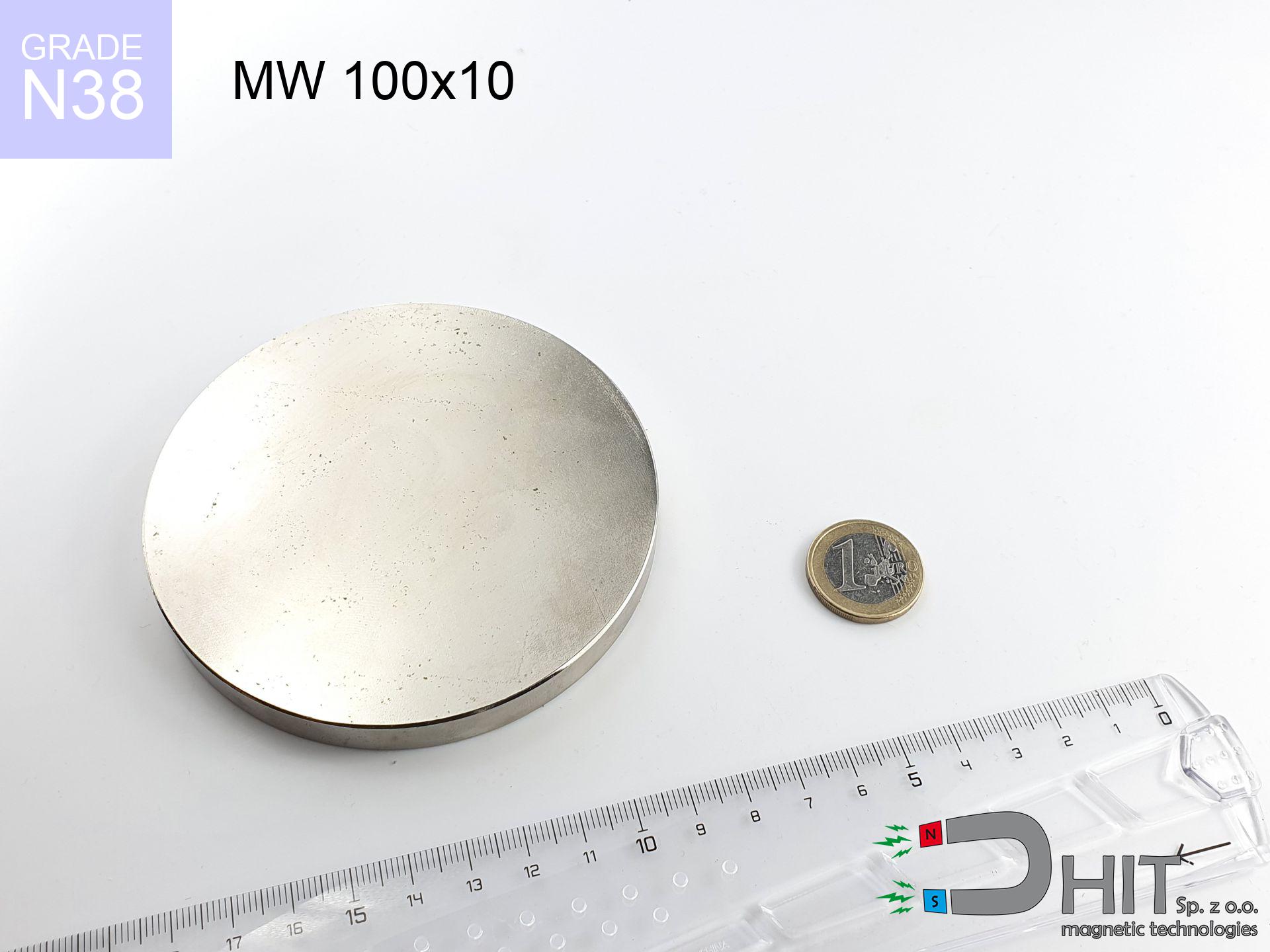
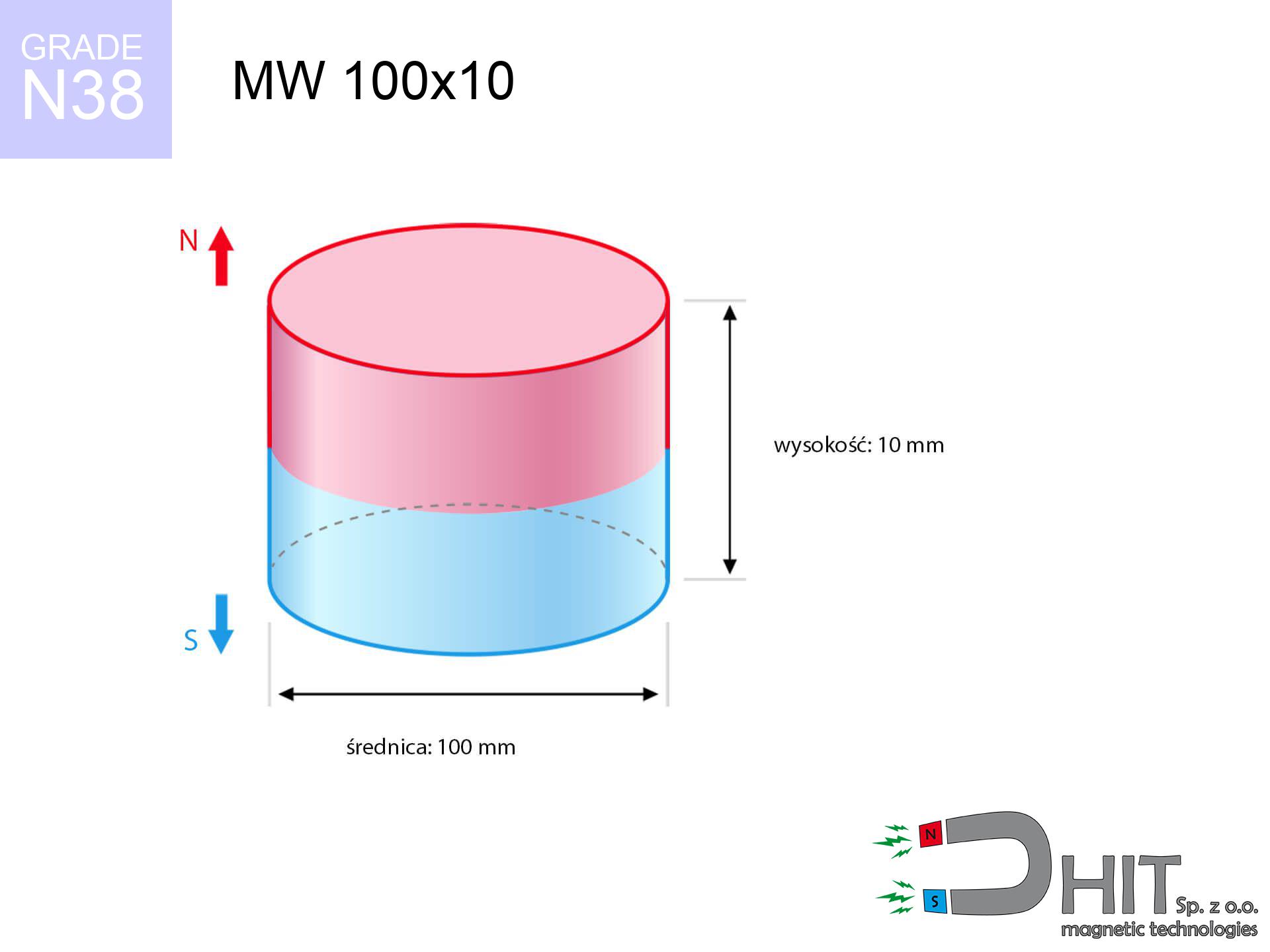
MW 100x10 / N38 - cylindrical magnet
cylindrical magnet
Catalog no 010001
GTIN/EAN: 5906301810018
Diameter Ø
100 mm [±0,1 mm]
Height
10 mm [±0,1 mm]
Weight
589.05 g
Magnetization Direction
↑ axial
Load capacity
40.86 kg / 400.80 N
Magnetic Induction
121.59 mT / 1216 Gs
Coating
[NiCuNi] Nickel
368.50 ZŁ with VAT / pcs + price for transport
299.59 ZŁ net + 23% VAT / pcs
bulk discounts:
Need more?
Contact us by phone
+48 888 99 98 98
if you prefer drop us a message via
contact form
the contact form page.
Weight as well as shape of neodymium magnets can be verified with our
magnetic calculator.
Same-day shipping for orders placed before 14:00.
Physical properties - MW 100x10 / N38 - cylindrical magnet
Specification / characteristics - MW 100x10 / N38 - cylindrical magnet
| properties | values |
|---|---|
| Cat. no. | 010001 |
| GTIN/EAN | 5906301810018 |
| Production/Distribution | Dhit sp. z o.o. |
| Country of origin | Poland / China / Germany |
| Customs code | 85059029 |
| Diameter Ø | 100 mm [±0,1 mm] |
| Height | 10 mm [±0,1 mm] |
| Weight | 589.05 g |
| Magnetization Direction | ↑ axial |
| Load capacity ~ ? | 40.86 kg / 400.80 N |
| Magnetic Induction ~ ? | 121.59 mT / 1216 Gs |
| Coating | [NiCuNi] Nickel |
| Manufacturing Tolerance | ±0.1 mm |
Magnetic properties of material N38
| properties | values | units |
|---|---|---|
| remenance Br [min. - max.] ? | 12.2-12.6 | kGs |
| remenance Br [min. - max.] ? | 1220-1260 | mT |
| coercivity bHc ? | 10.8-11.5 | kOe |
| coercivity bHc ? | 860-915 | kA/m |
| actual internal force iHc | ≥ 12 | kOe |
| actual internal force iHc | ≥ 955 | kA/m |
| energy density [min. - max.] ? | 36-38 | BH max MGOe |
| energy density [min. - max.] ? | 287-303 | BH max KJ/m |
| max. temperature ? | ≤ 80 | °C |
Physical properties of sintered neodymium magnets Nd2Fe14B at 20°C
| properties | values | units |
|---|---|---|
| Vickers hardness | ≥550 | Hv |
| Density | ≥7.4 | g/cm3 |
| Curie Temperature TC | 312 - 380 | °C |
| Curie Temperature TF | 593 - 716 | °F |
| Specific resistance | 150 | μΩ⋅cm |
| Bending strength | 250 | MPa |
| Compressive strength | 1000~1100 | MPa |
| Thermal expansion parallel (∥) to orientation (M) | (3-4) x 10-6 | °C-1 |
| Thermal expansion perpendicular (⊥) to orientation (M) | -(1-3) x 10-6 | °C-1 |
| Young's modulus | 1.7 x 10⁴ | kg/mm² |
Technical modeling of the assembly - data
Presented information represent the outcome of a mathematical analysis. Results are based on algorithms for the class Nd2Fe14B. Operational performance may deviate from the simulation results. Treat these data as a preliminary roadmap for designers.
Table 1: Static force (force vs distance) - interaction chart
MW 100x10 / N38
| Distance (mm) | Induction (Gauss) / mT | Pull Force (kg/lbs/g/N) | Risk Status |
|---|---|---|---|
| 0 mm |
1216 Gs
121.6 mT
|
40.86 kg / 90.08 pounds
40860.0 g / 400.8 N
|
dangerous! |
| 1 mm |
1208 Gs
120.8 mT
|
40.35 kg / 88.95 pounds
40345.4 g / 395.8 N
|
dangerous! |
| 2 mm |
1199 Gs
119.9 mT
|
39.74 kg / 87.62 pounds
39742.7 g / 389.9 N
|
dangerous! |
| 3 mm |
1189 Gs
118.9 mT
|
39.06 kg / 86.12 pounds
39062.0 g / 383.2 N
|
dangerous! |
| 5 mm |
1165 Gs
116.5 mT
|
37.49 kg / 82.65 pounds
37490.2 g / 367.8 N
|
dangerous! |
| 10 mm |
1087 Gs
108.7 mT
|
32.64 kg / 71.96 pounds
32640.7 g / 320.2 N
|
dangerous! |
| 15 mm |
991 Gs
99.1 mT
|
27.15 kg / 59.86 pounds
27153.9 g / 266.4 N
|
dangerous! |
| 20 mm |
887 Gs
88.7 mT
|
21.76 kg / 47.97 pounds
21758.7 g / 213.5 N
|
dangerous! |
| 30 mm |
683 Gs
68.3 mT
|
12.90 kg / 28.45 pounds
12902.7 g / 126.6 N
|
dangerous! |
| 50 mm |
379 Gs
37.9 mT
|
3.97 kg / 8.75 pounds
3968.4 g / 38.9 N
|
strong |
Table 2: Vertical hold (wall)
MW 100x10 / N38
| Distance (mm) | Friction coefficient | Pull Force (kg/lbs/g/N) |
|---|---|---|
| 0 mm | Stal (~0.2) |
8.17 kg / 18.02 pounds
8172.0 g / 80.2 N
|
| 1 mm | Stal (~0.2) |
8.07 kg / 17.79 pounds
8070.0 g / 79.2 N
|
| 2 mm | Stal (~0.2) |
7.95 kg / 17.52 pounds
7948.0 g / 78.0 N
|
| 3 mm | Stal (~0.2) |
7.81 kg / 17.22 pounds
7812.0 g / 76.6 N
|
| 5 mm | Stal (~0.2) |
7.50 kg / 16.53 pounds
7498.0 g / 73.6 N
|
| 10 mm | Stal (~0.2) |
6.53 kg / 14.39 pounds
6528.0 g / 64.0 N
|
| 15 mm | Stal (~0.2) |
5.43 kg / 11.97 pounds
5430.0 g / 53.3 N
|
| 20 mm | Stal (~0.2) |
4.35 kg / 9.59 pounds
4352.0 g / 42.7 N
|
| 30 mm | Stal (~0.2) |
2.58 kg / 5.69 pounds
2580.0 g / 25.3 N
|
| 50 mm | Stal (~0.2) |
0.79 kg / 1.75 pounds
794.0 g / 7.8 N
|
Table 3: Wall mounting (sliding) - behavior on slippery surfaces
MW 100x10 / N38
| Surface type | Friction coefficient / % Mocy | Max load (kg/lbs/g/N) |
|---|---|---|
| Raw steel |
µ = 0.3
30% Nominalnej Siły
|
12.26 kg / 27.02 pounds
12258.0 g / 120.3 N
|
| Painted steel (standard) |
µ = 0.2
20% Nominalnej Siły
|
8.17 kg / 18.02 pounds
8172.0 g / 80.2 N
|
| Oily/slippery steel |
µ = 0.1
10% Nominalnej Siły
|
4.09 kg / 9.01 pounds
4086.0 g / 40.1 N
|
| Magnet with anti-slip rubber |
µ = 0.5
50% Nominalnej Siły
|
20.43 kg / 45.04 pounds
20430.0 g / 200.4 N
|
Table 4: Material efficiency (substrate influence) - sheet metal selection
MW 100x10 / N38
| Steel thickness (mm) | % power | Real pull force (kg/lbs/g/N) |
|---|---|---|
| 0.5 mm |
|
2.04 kg / 4.50 pounds
2043.0 g / 20.0 N
|
| 1 mm |
|
5.11 kg / 11.26 pounds
5107.5 g / 50.1 N
|
| 2 mm |
|
10.22 kg / 22.52 pounds
10215.0 g / 100.2 N
|
| 3 mm |
|
15.32 kg / 33.78 pounds
15322.5 g / 150.3 N
|
| 5 mm |
|
25.54 kg / 56.30 pounds
25537.5 g / 250.5 N
|
| 10 mm |
|
40.86 kg / 90.08 pounds
40860.0 g / 400.8 N
|
| 11 mm |
|
40.86 kg / 90.08 pounds
40860.0 g / 400.8 N
|
| 12 mm |
|
40.86 kg / 90.08 pounds
40860.0 g / 400.8 N
|
Table 5: Working in heat (stability) - thermal limit
MW 100x10 / N38
| Ambient temp. (°C) | Power loss | Remaining pull (kg/lbs/g/N) | Status |
|---|---|---|---|
| 20 °C | 0.0% |
40.86 kg / 90.08 pounds
40860.0 g / 400.8 N
|
OK |
| 40 °C | -2.2% |
39.96 kg / 88.10 pounds
39961.1 g / 392.0 N
|
OK |
| 60 °C | -4.4% |
39.06 kg / 86.12 pounds
39062.2 g / 383.2 N
|
|
| 80 °C | -6.6% |
38.16 kg / 84.14 pounds
38163.2 g / 374.4 N
|
|
| 100 °C | -28.8% |
29.09 kg / 64.14 pounds
29092.3 g / 285.4 N
|
Table 6: Magnet-Magnet interaction (attraction) - forces in the system
MW 100x10 / N38
| Gap (mm) | Attraction (kg/lbs) (N-S) | Shear Force (kg/lbs/g/N) | Repulsion (kg/lbs) (N-N) |
|---|---|---|---|
| 0 mm |
71.58 kg / 157.80 pounds
2 302 Gs
|
10.74 kg / 23.67 pounds
10737 g / 105.3 N
|
N/A |
| 1 mm |
71.15 kg / 156.86 pounds
2 424 Gs
|
10.67 kg / 23.53 pounds
10673 g / 104.7 N
|
64.04 kg / 141.17 pounds
~0 Gs
|
| 2 mm |
70.68 kg / 155.82 pounds
2 416 Gs
|
10.60 kg / 23.37 pounds
10602 g / 104.0 N
|
63.61 kg / 140.23 pounds
~0 Gs
|
| 3 mm |
70.17 kg / 154.69 pounds
2 408 Gs
|
10.53 kg / 23.20 pounds
10525 g / 103.3 N
|
63.15 kg / 139.22 pounds
~0 Gs
|
| 5 mm |
69.04 kg / 152.21 pounds
2 388 Gs
|
10.36 kg / 22.83 pounds
10356 g / 101.6 N
|
62.14 kg / 136.99 pounds
~0 Gs
|
| 10 mm |
65.68 kg / 144.79 pounds
2 329 Gs
|
9.85 kg / 21.72 pounds
9851 g / 96.6 N
|
59.11 kg / 130.31 pounds
~0 Gs
|
| 20 mm |
57.18 kg / 126.06 pounds
2 173 Gs
|
8.58 kg / 18.91 pounds
8577 g / 84.1 N
|
51.46 kg / 113.45 pounds
~0 Gs
|
| 50 mm |
29.67 kg / 65.40 pounds
1 565 Gs
|
4.45 kg / 9.81 pounds
4450 g / 43.7 N
|
26.70 kg / 58.86 pounds
~0 Gs
|
| 60 mm |
22.60 kg / 49.83 pounds
1 366 Gs
|
3.39 kg / 7.47 pounds
3390 g / 33.3 N
|
20.34 kg / 44.85 pounds
~0 Gs
|
| 70 mm |
16.98 kg / 37.43 pounds
1 184 Gs
|
2.55 kg / 5.61 pounds
2546 g / 25.0 N
|
15.28 kg / 33.68 pounds
~0 Gs
|
| 80 mm |
12.64 kg / 27.87 pounds
1 022 Gs
|
1.90 kg / 4.18 pounds
1896 g / 18.6 N
|
11.38 kg / 25.08 pounds
~0 Gs
|
| 90 mm |
9.38 kg / 20.67 pounds
880 Gs
|
1.41 kg / 3.10 pounds
1406 g / 13.8 N
|
8.44 kg / 18.60 pounds
~0 Gs
|
| 100 mm |
6.95 kg / 15.33 pounds
758 Gs
|
1.04 kg / 2.30 pounds
1043 g / 10.2 N
|
6.26 kg / 13.79 pounds
~0 Gs
|
Table 7: Hazards (electronics) - warnings
MW 100x10 / N38
| Object / Device | Limit (Gauss) / mT | Safe distance |
|---|---|---|
| Pacemaker | 5 Gs (0.5 mT) | 31.0 cm |
| Hearing aid | 10 Gs (1.0 mT) | 24.0 cm |
| Timepiece | 20 Gs (2.0 mT) | 19.0 cm |
| Phone / Smartphone | 40 Gs (4.0 mT) | 14.5 cm |
| Car key | 50 Gs (5.0 mT) | 13.5 cm |
| Payment card | 400 Gs (40.0 mT) | 5.0 cm |
| HDD hard drive | 600 Gs (60.0 mT) | 3.5 cm |
Table 8: Dynamics (cracking risk) - collision effects
MW 100x10 / N38
| Start from (mm) | Speed (km/h) | Energy (J) | Predicted outcome |
|---|---|---|---|
| 10 mm |
11.87 km/h
(3.30 m/s)
|
3.20 J | |
| 30 mm |
17.18 km/h
(4.77 m/s)
|
6.71 J | |
| 50 mm |
19.89 km/h
(5.52 m/s)
|
8.99 J | |
| 100 mm |
26.67 km/h
(7.41 m/s)
|
16.17 J |
Table 9: Surface protection spec
MW 100x10 / N38
| Technical parameter | Value / Description |
|---|---|
| Coating type | [NiCuNi] Nickel |
| Layer structure | Nickel - Copper - Nickel |
| Layer thickness | 10-20 µm |
| Salt spray test (SST) ? | 24 h |
| Recommended environment | Indoors only (dry) |
Table 10: Electrical data (Flux)
MW 100x10 / N38
| Parameter | Value | SI Unit / Description |
|---|---|---|
| Magnetic Flux | 125 951 Mx | 1259.5 µWb |
| Pc Coefficient | 0.16 | Low (Flat) |
Table 11: Underwater work (magnet fishing)
MW 100x10 / N38
| Environment | Effective steel pull | Effect |
|---|---|---|
| Air (land) | 40.86 kg | Standard |
| Water (riverbed) |
46.78 kg
(+5.92 kg buoyancy gain)
|
+14.5% |
1. Shear force
*Note: On a vertical wall, the magnet holds only approx. 20-30% of its nominal pull.
2. Steel thickness impact
*Thin metal sheet (e.g. 0.5mm PC case) significantly weakens the holding force.
3. Heat tolerance
*For N38 material, the critical limit is 80°C.
4. Demagnetization curve and operating point (B-H)
chart generated for the permeance coefficient Pc (Permeance Coefficient) = 0.16
This simulation demonstrates the magnetic stability of the selected magnet under specific geometric conditions. The solid red line represents the demagnetization curve (material potential), while the dashed blue line is the load line based on the magnet's geometry. The Pc (Permeance Coefficient), also known as the load line slope, is a dimensionless value that describes the relationship between the magnet's shape and its magnetic stability. The intersection of these two lines (the black dot) is the operating point — it determines the actual magnetic flux density generated by the magnet in this specific configuration. A higher Pc value means the magnet is more 'slender' (tall relative to its area), resulting in a higher operating point and better resistance to irreversible demagnetization caused by external fields or temperature. A value of 0.42 is relatively low (typical for flat magnets), meaning the operating point is closer to the 'knee' of the curve — caution is advised when operating at temperatures near the maximum limit to avoid strength loss.
Elemental analysis
| iron (Fe) | 64% – 68% |
| neodymium (Nd) | 29% – 32% |
| boron (B) | 1.1% – 1.2% |
| dysprosium (Dy) | 0.5% – 2.0% |
| coating (Ni-Cu-Ni) | < 0.05% |
Ecology and recycling (GPSR)
| recyclability (EoL) | 100% |
| recycled raw materials | ~10% (pre-cons) |
| carbon footprint | low / zredukowany |
| waste code (EWC) | 16 02 16 |
Other proposals


Strengths as well as weaknesses of neodymium magnets.
Advantages
- They virtually do not lose strength, because even after ten years the performance loss is only ~1% (based on calculations),
- Magnets perfectly defend themselves against demagnetization caused by external fields,
- Thanks to the shiny finish, the surface of nickel, gold, or silver gives an professional appearance,
- They show high magnetic induction at the operating surface, making them more effective,
- Due to their durability and thermal resistance, neodymium magnets can operate (depending on the shape) even at high temperatures reaching 230°C or more...
- Considering the ability of accurate molding and customization to custom solutions, neodymium magnets can be produced in a variety of forms and dimensions, which amplifies use scope,
- Huge importance in modern industrial fields – they find application in hard drives, electric motors, medical equipment, and modern systems.
- Thanks to efficiency per cm³, small magnets offer high operating force, in miniature format,
Limitations
- To avoid cracks upon strong impacts, we suggest using special steel housings. Such a solution secures the magnet and simultaneously increases its durability.
- Neodymium magnets lose their strength under the influence of heating. As soon as 80°C is exceeded, many of them start losing their power. Therefore, we recommend our special magnets marked [AH], which maintain durability even at temperatures up to 230°C
- They oxidize in a humid environment - during use outdoors we advise using waterproof magnets e.g. in rubber, plastic
- We suggest casing - magnetic mount, due to difficulties in producing nuts inside the magnet and complicated shapes.
- Possible danger resulting from small fragments of magnets pose a threat, if swallowed, which becomes key in the context of child health protection. Furthermore, tiny parts of these magnets can disrupt the diagnostic process medical in case of swallowing.
- With budget limitations the cost of neodymium magnets can be a barrier,
Pull force analysis
Detachment force of the magnet in optimal conditions – what contributes to it?
- on a block made of structural steel, perfectly concentrating the magnetic field
- with a cross-section no less than 10 mm
- characterized by even structure
- with direct contact (without paint)
- under axial force vector (90-degree angle)
- at conditions approx. 20°C
Practical lifting capacity: influencing factors
- Gap between surfaces – every millimeter of separation (caused e.g. by varnish or dirt) significantly weakens the magnet efficiency, often by half at just 0.5 mm.
- Force direction – remember that the magnet has greatest strength perpendicularly. Under sliding down, the holding force drops significantly, often to levels of 20-30% of the nominal value.
- Wall thickness – thin material does not allow full use of the magnet. Magnetic flux passes through the material instead of converting into lifting capacity.
- Chemical composition of the base – mild steel attracts best. Alloy admixtures lower magnetic properties and lifting capacity.
- Smoothness – ideal contact is possible only on smooth steel. Any scratches and bumps create air cushions, reducing force.
- Thermal factor – high temperature reduces pulling force. Exceeding the limit temperature can permanently demagnetize the magnet.
Lifting capacity was assessed with the use of a smooth steel plate of suitable thickness (min. 20 mm), under perpendicular pulling force, in contrast under parallel forces the load capacity is reduced by as much as fivefold. Additionally, even a small distance between the magnet and the plate reduces the lifting capacity.
Safe handling of NdFeB magnets
Operating temperature
Keep cool. NdFeB magnets are susceptible to temperature. If you require operation above 80°C, look for special high-temperature series (H, SH, UH).
Safe operation
Exercise caution. Rare earth magnets act from a long distance and connect with huge force, often faster than you can react.
Threat to electronics
Avoid bringing magnets close to a wallet, laptop, or TV. The magnetism can destroy these devices and wipe information from cards.
Flammability
Mechanical processing of neodymium magnets poses a fire hazard. Magnetic powder reacts violently with oxygen and is hard to extinguish.
Protective goggles
Despite metallic appearance, neodymium is delicate and not impact-resistant. Avoid impacts, as the magnet may crumble into sharp, dangerous pieces.
Bone fractures
Large magnets can crush fingers instantly. Never put your hand betwixt two strong magnets.
Metal Allergy
A percentage of the population have a contact allergy to nickel, which is the typical protective layer for neodymium magnets. Extended handling can result in an allergic reaction. We recommend wear safety gloves.
Swallowing risk
Absolutely store magnets out of reach of children. Choking hazard is significant, and the effects of magnets clamping inside the body are life-threatening.
Danger to pacemakers
Health Alert: Strong magnets can deactivate pacemakers and defibrillators. Do not approach if you have medical devices.
Impact on smartphones
Be aware: rare earth magnets generate a field that disrupts precision electronics. Keep a safe distance from your mobile, device, and navigation systems.
Tabela kosztu i czasu dostawy
Płatność przed wysyłką:

GLS kurier
Przesyłka będzie u Ciebie za 2-3 dni
14.99 ZŁ

InPost Paczkomaty 24/7
Przesyłka będzie u Ciebie za 1-2 dni
12.30 ZŁ
Płatność przy odbiorze (pobranie):
GLS kurier
Przesyłka będzie u Ciebie za 1-2 dni
23.00 ZŁ
Rate the product
Your rating