
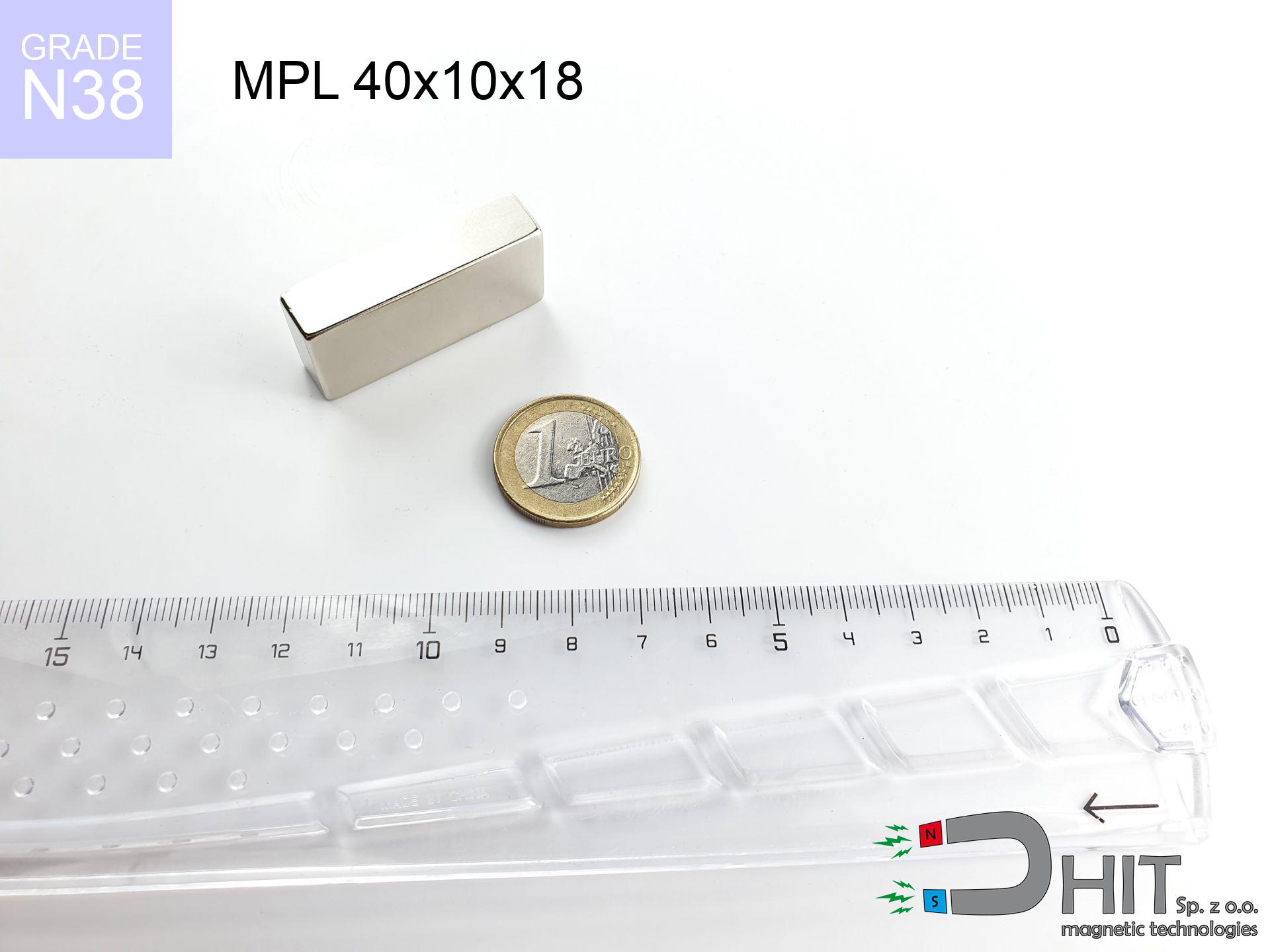
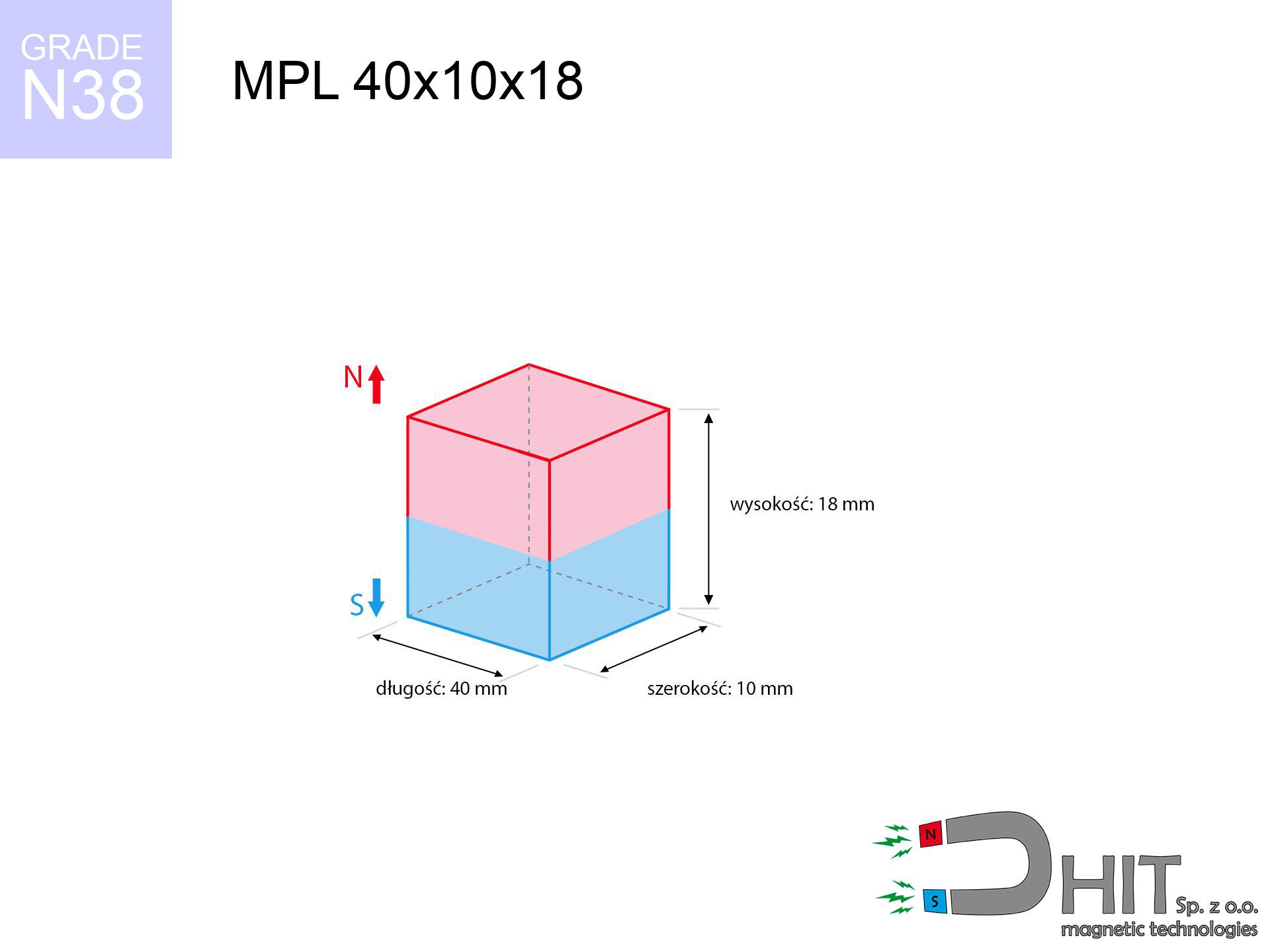
MPL 40x10x18 / N38 - lamellar magnet
lamellar magnet
Catalog no 020149
GTIN/EAN: 5906301811558
length
40 mm [±0,1 mm]
Width
10 mm [±0,1 mm]
Height
18 mm [±0,1 mm]
Weight
54 g
Magnetization Direction
→ diametrical
Load capacity
16.72 kg / 164.01 N
Magnetic Induction
540.48 mT / 5405 Gs
Coating
[NiCuNi] Nickel
18.45 ZŁ with VAT / pcs + price for transport
15.00 ZŁ net + 23% VAT / pcs
bulk discounts:
Need more?
Contact us by phone
+48 888 99 98 98
alternatively send us a note via
inquiry form
through our site.
Specifications and form of magnets can be estimated with our
magnetic mass calculator.
Order by 14:00 and we’ll ship today!
Technical of the product - MPL 40x10x18 / N38 - lamellar magnet
Specification / characteristics - MPL 40x10x18 / N38 - lamellar magnet
| properties | values |
|---|---|
| Cat. no. | 020149 |
| GTIN/EAN | 5906301811558 |
| Production/Distribution | Dhit sp. z o.o. |
| Country of origin | Poland / China / Germany |
| Customs code | 85059029 |
| length | 40 mm [±0,1 mm] |
| Width | 10 mm [±0,1 mm] |
| Height | 18 mm [±0,1 mm] |
| Weight | 54 g |
| Magnetization Direction | → diametrical |
| Load capacity ~ ? | 16.72 kg / 164.01 N |
| Magnetic Induction ~ ? | 540.48 mT / 5405 Gs |
| Coating | [NiCuNi] Nickel |
| Manufacturing Tolerance | ±0.1 mm |
Magnetic properties of material N38
| properties | values | units |
|---|---|---|
| remenance Br [min. - max.] ? | 12.2-12.6 | kGs |
| remenance Br [min. - max.] ? | 1220-1260 | mT |
| coercivity bHc ? | 10.8-11.5 | kOe |
| coercivity bHc ? | 860-915 | kA/m |
| actual internal force iHc | ≥ 12 | kOe |
| actual internal force iHc | ≥ 955 | kA/m |
| energy density [min. - max.] ? | 36-38 | BH max MGOe |
| energy density [min. - max.] ? | 287-303 | BH max KJ/m |
| max. temperature ? | ≤ 80 | °C |
Physical properties of sintered neodymium magnets Nd2Fe14B at 20°C
| properties | values | units |
|---|---|---|
| Vickers hardness | ≥550 | Hv |
| Density | ≥7.4 | g/cm3 |
| Curie Temperature TC | 312 - 380 | °C |
| Curie Temperature TF | 593 - 716 | °F |
| Specific resistance | 150 | μΩ⋅cm |
| Bending strength | 250 | MPa |
| Compressive strength | 1000~1100 | MPa |
| Thermal expansion parallel (∥) to orientation (M) | (3-4) x 10-6 | °C-1 |
| Thermal expansion perpendicular (⊥) to orientation (M) | -(1-3) x 10-6 | °C-1 |
| Young's modulus | 1.7 x 10⁴ | kg/mm² |
Engineering analysis of the assembly - technical parameters
The following information constitute the direct effect of a mathematical calculation. Values are based on algorithms for the material Nd2Fe14B. Operational conditions may deviate from the simulation results. Use these calculations as a reference point for designers.
Table 1: Static pull force (force vs distance) - interaction chart
MPL 40x10x18 / N38
| Distance (mm) | Induction (Gauss) / mT | Pull Force (kg/lbs/g/N) | Risk Status |
|---|---|---|---|
| 0 mm |
5402 Gs
540.2 mT
|
16.72 kg / 36.86 pounds
16720.0 g / 164.0 N
|
dangerous! |
| 1 mm |
4664 Gs
466.4 mT
|
12.46 kg / 27.48 pounds
12464.6 g / 122.3 N
|
dangerous! |
| 2 mm |
3970 Gs
397.0 mT
|
9.03 kg / 19.90 pounds
9028.7 g / 88.6 N
|
medium risk |
| 3 mm |
3362 Gs
336.2 mT
|
6.48 kg / 14.28 pounds
6476.4 g / 63.5 N
|
medium risk |
| 5 mm |
2432 Gs
243.2 mT
|
3.39 kg / 7.47 pounds
3388.5 g / 33.2 N
|
medium risk |
| 10 mm |
1220 Gs
122.0 mT
|
0.85 kg / 1.88 pounds
853.2 g / 8.4 N
|
low risk |
| 15 mm |
703 Gs
70.3 mT
|
0.28 kg / 0.62 pounds
282.9 g / 2.8 N
|
low risk |
| 20 mm |
440 Gs
44.0 mT
|
0.11 kg / 0.24 pounds
111.1 g / 1.1 N
|
low risk |
| 30 mm |
203 Gs
20.3 mT
|
0.02 kg / 0.05 pounds
23.6 g / 0.2 N
|
low risk |
| 50 mm |
64 Gs
6.4 mT
|
0.00 kg / 0.01 pounds
2.4 g / 0.0 N
|
low risk |
Table 2: Slippage load (vertical surface)
MPL 40x10x18 / N38
| Distance (mm) | Friction coefficient | Pull Force (kg/lbs/g/N) |
|---|---|---|
| 0 mm | Stal (~0.2) |
3.34 kg / 7.37 pounds
3344.0 g / 32.8 N
|
| 1 mm | Stal (~0.2) |
2.49 kg / 5.49 pounds
2492.0 g / 24.4 N
|
| 2 mm | Stal (~0.2) |
1.81 kg / 3.98 pounds
1806.0 g / 17.7 N
|
| 3 mm | Stal (~0.2) |
1.30 kg / 2.86 pounds
1296.0 g / 12.7 N
|
| 5 mm | Stal (~0.2) |
0.68 kg / 1.49 pounds
678.0 g / 6.7 N
|
| 10 mm | Stal (~0.2) |
0.17 kg / 0.37 pounds
170.0 g / 1.7 N
|
| 15 mm | Stal (~0.2) |
0.06 kg / 0.12 pounds
56.0 g / 0.5 N
|
| 20 mm | Stal (~0.2) |
0.02 kg / 0.05 pounds
22.0 g / 0.2 N
|
| 30 mm | Stal (~0.2) |
0.00 kg / 0.01 pounds
4.0 g / 0.0 N
|
| 50 mm | Stal (~0.2) |
0.00 kg / 0.00 pounds
0.0 g / 0.0 N
|
Table 3: Vertical assembly (sliding) - vertical pull
MPL 40x10x18 / N38
| Surface type | Friction coefficient / % Mocy | Max load (kg/lbs/g/N) |
|---|---|---|
| Raw steel |
µ = 0.3
30% Nominalnej Siły
|
5.02 kg / 11.06 pounds
5016.0 g / 49.2 N
|
| Painted steel (standard) |
µ = 0.2
20% Nominalnej Siły
|
3.34 kg / 7.37 pounds
3344.0 g / 32.8 N
|
| Oily/slippery steel |
µ = 0.1
10% Nominalnej Siły
|
1.67 kg / 3.69 pounds
1672.0 g / 16.4 N
|
| Magnet with anti-slip rubber |
µ = 0.5
50% Nominalnej Siły
|
8.36 kg / 18.43 pounds
8360.0 g / 82.0 N
|
Table 4: Material efficiency (saturation) - sheet metal selection
MPL 40x10x18 / N38
| Steel thickness (mm) | % power | Real pull force (kg/lbs/g/N) |
|---|---|---|
| 0.5 mm |
|
0.84 kg / 1.84 pounds
836.0 g / 8.2 N
|
| 1 mm |
|
2.09 kg / 4.61 pounds
2090.0 g / 20.5 N
|
| 2 mm |
|
4.18 kg / 9.22 pounds
4180.0 g / 41.0 N
|
| 3 mm |
|
6.27 kg / 13.82 pounds
6270.0 g / 61.5 N
|
| 5 mm |
|
10.45 kg / 23.04 pounds
10450.0 g / 102.5 N
|
| 10 mm |
|
16.72 kg / 36.86 pounds
16720.0 g / 164.0 N
|
| 11 mm |
|
16.72 kg / 36.86 pounds
16720.0 g / 164.0 N
|
| 12 mm |
|
16.72 kg / 36.86 pounds
16720.0 g / 164.0 N
|
Table 5: Thermal stability (material behavior) - thermal limit
MPL 40x10x18 / N38
| Ambient temp. (°C) | Power loss | Remaining pull (kg/lbs/g/N) | Status |
|---|---|---|---|
| 20 °C | 0.0% |
16.72 kg / 36.86 pounds
16720.0 g / 164.0 N
|
OK |
| 40 °C | -2.2% |
16.35 kg / 36.05 pounds
16352.2 g / 160.4 N
|
OK |
| 60 °C | -4.4% |
15.98 kg / 35.24 pounds
15984.3 g / 156.8 N
|
OK |
| 80 °C | -6.6% |
15.62 kg / 34.43 pounds
15616.5 g / 153.2 N
|
|
| 100 °C | -28.8% |
11.90 kg / 26.25 pounds
11904.6 g / 116.8 N
|
Table 6: Two magnets (repulsion) - forces in the system
MPL 40x10x18 / N38
| Gap (mm) | Attraction (kg/lbs) (N-S) | Lateral Force (kg/lbs/g/N) | Repulsion (kg/lbs) (N-N) |
|---|---|---|---|
| 0 mm |
71.96 kg / 158.65 pounds
5 928 Gs
|
10.79 kg / 23.80 pounds
10794 g / 105.9 N
|
N/A |
| 1 mm |
62.49 kg / 137.76 pounds
10 068 Gs
|
9.37 kg / 20.66 pounds
9373 g / 91.9 N
|
56.24 kg / 123.98 pounds
~0 Gs
|
| 2 mm |
53.65 kg / 118.27 pounds
9 328 Gs
|
8.05 kg / 17.74 pounds
8047 g / 78.9 N
|
48.28 kg / 106.44 pounds
~0 Gs
|
| 3 mm |
45.76 kg / 100.88 pounds
8 615 Gs
|
6.86 kg / 15.13 pounds
6864 g / 67.3 N
|
41.18 kg / 90.79 pounds
~0 Gs
|
| 5 mm |
32.92 kg / 72.58 pounds
7 308 Gs
|
4.94 kg / 10.89 pounds
4938 g / 48.4 N
|
29.63 kg / 65.32 pounds
~0 Gs
|
| 10 mm |
14.58 kg / 32.15 pounds
4 864 Gs
|
2.19 kg / 4.82 pounds
2188 g / 21.5 N
|
13.13 kg / 28.94 pounds
~0 Gs
|
| 20 mm |
3.67 kg / 8.10 pounds
2 441 Gs
|
0.55 kg / 1.21 pounds
551 g / 5.4 N
|
3.30 kg / 7.29 pounds
~0 Gs
|
| 50 mm |
0.21 kg / 0.46 pounds
585 Gs
|
0.03 kg / 0.07 pounds
32 g / 0.3 N
|
0.19 kg / 0.42 pounds
~0 Gs
|
| 60 mm |
0.10 kg / 0.22 pounds
406 Gs
|
0.02 kg / 0.03 pounds
15 g / 0.1 N
|
0.09 kg / 0.20 pounds
~0 Gs
|
| 70 mm |
0.05 kg / 0.12 pounds
293 Gs
|
0.01 kg / 0.02 pounds
8 g / 0.1 N
|
0.05 kg / 0.10 pounds
~0 Gs
|
| 80 mm |
0.03 kg / 0.06 pounds
217 Gs
|
0.00 kg / 0.01 pounds
4 g / 0.0 N
|
0.03 kg / 0.06 pounds
~0 Gs
|
| 90 mm |
0.02 kg / 0.04 pounds
165 Gs
|
0.00 kg / 0.01 pounds
3 g / 0.0 N
|
0.02 kg / 0.03 pounds
~0 Gs
|
| 100 mm |
0.01 kg / 0.02 pounds
128 Gs
|
0.00 kg / 0.00 pounds
2 g / 0.0 N
|
0.01 kg / 0.02 pounds
~0 Gs
|
Table 7: Protective zones (electronics) - warnings
MPL 40x10x18 / N38
| Object / Device | Limit (Gauss) / mT | Safe distance |
|---|---|---|
| Pacemaker | 5 Gs (0.5 mT) | 13.5 cm |
| Hearing aid | 10 Gs (1.0 mT) | 10.5 cm |
| Mechanical watch | 20 Gs (2.0 mT) | 8.0 cm |
| Mobile device | 40 Gs (4.0 mT) | 6.5 cm |
| Remote | 50 Gs (5.0 mT) | 6.0 cm |
| Payment card | 400 Gs (40.0 mT) | 2.5 cm |
| HDD hard drive | 600 Gs (60.0 mT) | 2.0 cm |
Table 8: Dynamics (kinetic energy) - collision effects
MPL 40x10x18 / N38
| Start from (mm) | Speed (km/h) | Energy (J) | Predicted outcome |
|---|---|---|---|
| 10 mm |
18.30 km/h
(5.08 m/s)
|
0.70 J | |
| 30 mm |
30.76 km/h
(8.55 m/s)
|
1.97 J | |
| 50 mm |
39.69 km/h
(11.02 m/s)
|
3.28 J | |
| 100 mm |
56.12 km/h
(15.59 m/s)
|
6.56 J |
Table 9: Corrosion resistance
MPL 40x10x18 / N38
| Technical parameter | Value / Description |
|---|---|
| Coating type | [NiCuNi] Nickel |
| Layer structure | Nickel - Copper - Nickel |
| Layer thickness | 10-20 µm |
| Salt spray test (SST) ? | 24 h |
| Recommended environment | Indoors only (dry) |
Table 10: Construction data (Flux)
MPL 40x10x18 / N38
| Parameter | Value | SI Unit / Description |
|---|---|---|
| Magnetic Flux | 21 285 Mx | 212.9 µWb |
| Pc Coefficient | 0.79 | High (Stable) |
Table 11: Submerged application
MPL 40x10x18 / N38
| Environment | Effective steel pull | Effect |
|---|---|---|
| Air (land) | 16.72 kg | Standard |
| Water (riverbed) |
19.14 kg
(+2.42 kg buoyancy gain)
|
+14.5% |
1. Wall mount (shear)
*Note: On a vertical surface, the magnet holds just approx. 20-30% of its max power.
2. Steel saturation
*Thin metal sheet (e.g. computer case) significantly reduces the holding force.
3. Thermal stability
*For N38 grade, the max working temp is 80°C.
4. Demagnetization curve and operating point (B-H)
chart generated for the permeance coefficient Pc (Permeance Coefficient) = 0.79
This simulation demonstrates the magnetic stability of the selected magnet under specific geometric conditions. The solid red line represents the demagnetization curve (material potential), while the dashed blue line is the load line based on the magnet's geometry. The Pc (Permeance Coefficient), also known as the load line slope, is a dimensionless value that describes the relationship between the magnet's shape and its magnetic stability. The intersection of these two lines (the black dot) is the operating point — it determines the actual magnetic flux density generated by the magnet in this specific configuration. A higher Pc value means the magnet is more 'slender' (tall relative to its area), resulting in a higher operating point and better resistance to irreversible demagnetization caused by external fields or temperature. A value of 0.42 is relatively low (typical for flat magnets), meaning the operating point is closer to the 'knee' of the curve — caution is advised when operating at temperatures near the maximum limit to avoid strength loss.
Chemical composition
| iron (Fe) | 64% – 68% |
| neodymium (Nd) | 29% – 32% |
| boron (B) | 1.1% – 1.2% |
| dysprosium (Dy) | 0.5% – 2.0% |
| coating (Ni-Cu-Ni) | < 0.05% |
Environmental data
| recyclability (EoL) | 100% |
| recycled raw materials | ~10% (pre-cons) |
| carbon footprint | low / zredukowany |
| waste code (EWC) | 16 02 16 |
Check out also products


![AM ucho [M10] - magnetic accessories](https://cdn3.dhit.pl/graphics/products/am-ucho-m10-tij.jpg "AM ucho [M10] - magnetic accessories")
Advantages and disadvantages of neodymium magnets.
Pros
- They retain attractive force for nearly ten years – the loss is just ~1% (in theory),
- They feature excellent resistance to magnetism drop when exposed to external magnetic sources,
- In other words, due to the reflective finish of gold, the element becomes visually attractive,
- Magnetic induction on the surface of the magnet is impressive,
- Due to their durability and thermal resistance, neodymium magnets can operate (depending on the shape) even at high temperatures reaching 230°C or more...
- Thanks to freedom in constructing and the ability to modify to specific needs,
- Versatile presence in electronics industry – they are commonly used in HDD drives, motor assemblies, advanced medical instruments, as well as modern systems.
- Relatively small size with high pulling force – neodymium magnets offer high power in tiny dimensions, which enables their usage in compact constructions
Limitations
- Susceptibility to cracking is one of their disadvantages. Upon intense impact they can fracture. We recommend keeping them in a steel housing, which not only protects them against impacts but also increases their durability
- When exposed to high temperature, neodymium magnets suffer a drop in strength. Often, when the temperature exceeds 80°C, their strength decreases (depending on the size and shape of the magnet). For those who need magnets for extreme conditions, we offer [AH] versions withstanding up to 230°C
- Magnets exposed to a humid environment can rust. Therefore when using outdoors, we recommend using water-impermeable magnets made of rubber, plastic or other material resistant to moisture
- Limited possibility of making threads in the magnet and complex shapes - preferred is casing - magnet mounting.
- Health risk to health – tiny shards of magnets are risky, if swallowed, which gains importance in the context of child safety. Furthermore, small elements of these products are able to be problematic in diagnostics medical when they are in the body.
- With large orders the cost of neodymium magnets is economically unviable,
Pull force analysis
Breakaway strength of the magnet in ideal conditions – what it depends on?
- with the contact of a yoke made of low-carbon steel, guaranteeing full magnetic saturation
- possessing a massiveness of minimum 10 mm to avoid saturation
- with an ideally smooth contact surface
- without any insulating layer between the magnet and steel
- for force applied at a right angle (pull-off, not shear)
- at temperature approx. 20 degrees Celsius
Impact of factors on magnetic holding capacity in practice
- Space between magnet and steel – every millimeter of distance (caused e.g. by varnish or dirt) drastically reduces the pulling force, often by half at just 0.5 mm.
- Angle of force application – maximum parameter is obtained only during perpendicular pulling. The force required to slide of the magnet along the surface is usually several times smaller (approx. 1/5 of the lifting capacity).
- Substrate thickness – for full efficiency, the steel must be adequately massive. Thin sheet restricts the attraction force (the magnet "punches through" it).
- Material composition – not every steel attracts identically. Alloy additives weaken the attraction effect.
- Surface condition – ground elements ensure maximum contact, which improves force. Uneven metal reduce efficiency.
- Thermal conditions – neodymium magnets have a negative temperature coefficient. When it is hot they lose power, and in frost gain strength (up to a certain limit).
Holding force was checked on a smooth steel plate of 20 mm thickness, when the force acted perpendicularly, whereas under shearing force the holding force is lower. Additionally, even a slight gap between the magnet’s surface and the plate reduces the holding force.
Safety rules for work with NdFeB magnets
Respect the power
Use magnets with awareness. Their immense force can surprise even experienced users. Stay alert and respect their power.
Finger safety
Danger of trauma: The pulling power is so great that it can result in hematomas, crushing, and broken bones. Use thick gloves.
Protect data
Powerful magnetic fields can erase data on payment cards, HDDs, and storage devices. Maintain a gap of at least 10 cm.
Precision electronics
A strong magnetic field disrupts the operation of compasses in phones and GPS navigation. Do not bring magnets close to a device to prevent damaging the sensors.
Operating temperature
Control the heat. Heating the magnet to high heat will destroy its properties and strength.
Do not give to children
Adult use only. Small elements can be swallowed, causing severe trauma. Keep away from kids and pets.
Medical implants
Warning for patients: Strong magnetic fields disrupt electronics. Keep minimum 30 cm distance or request help to handle the magnets.
Fire warning
Drilling and cutting of neodymium magnets carries a risk of fire risk. Neodymium dust reacts violently with oxygen and is difficult to extinguish.
Material brittleness
NdFeB magnets are ceramic materials, which means they are fragile like glass. Collision of two magnets leads to them shattering into shards.
Sensitization to coating
Certain individuals experience a contact allergy to nickel, which is the standard coating for NdFeB magnets. Prolonged contact may cause an allergic reaction. We suggest wear safety gloves.
Tabela kosztu i czasu dostawy
Płatność przed wysyłką:

GLS kurier
Przesyłka będzie u Ciebie za 2-3 dni
14.99 ZŁ

InPost Paczkomaty 24/7
Przesyłka będzie u Ciebie za 1-2 dni
12.30 ZŁ
Płatność przy odbiorze (pobranie):
GLS kurier
Przesyłka będzie u Ciebie za 1-2 dni
23.00 ZŁ
Rate the product
Your rating