
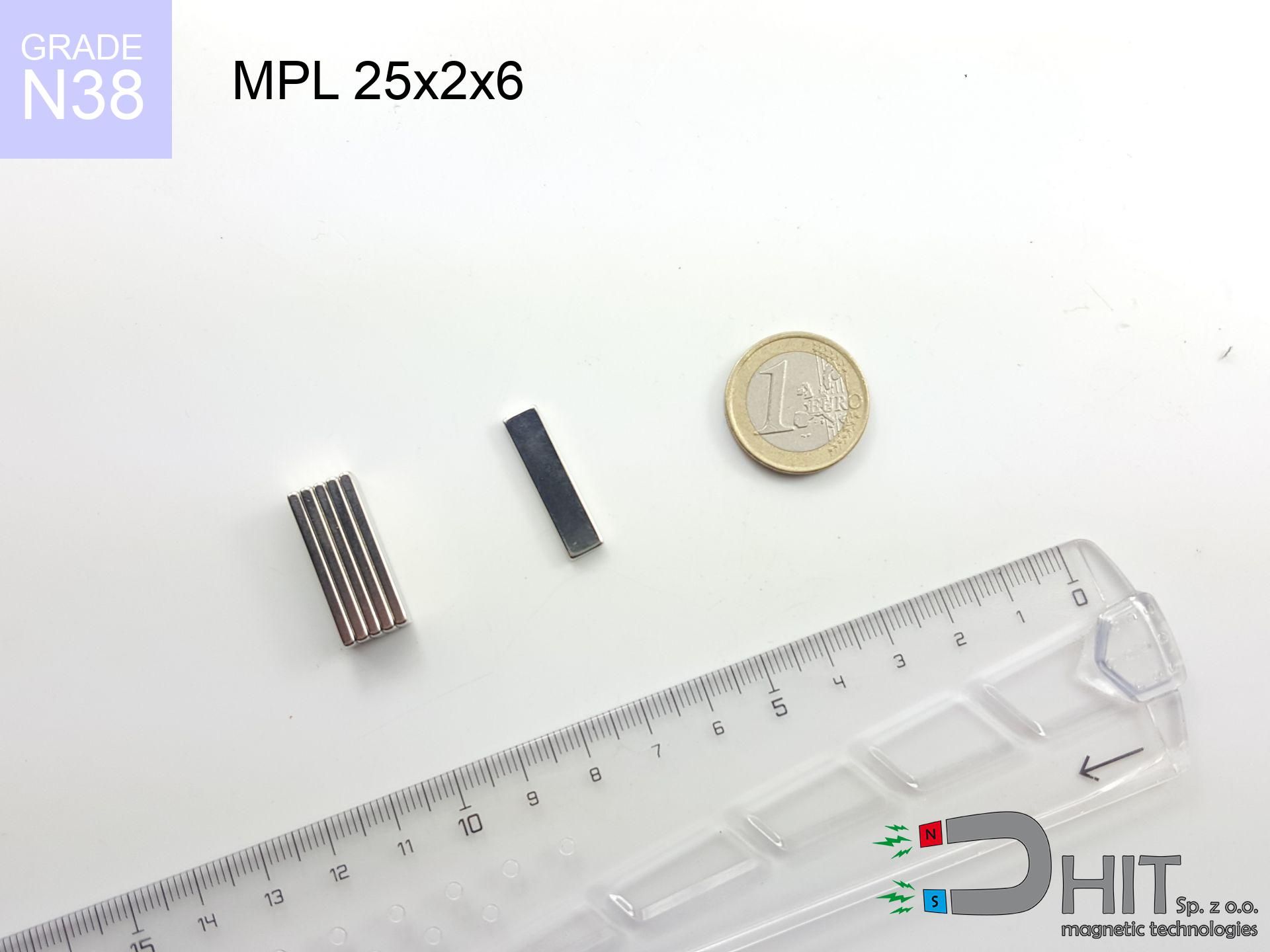
MPL 25x2x6 / N38 - lamellar magnet
lamellar magnet
Catalog no 020509
length
25 mm [±0,1 mm]
Width
2 mm [±0,1 mm]
Height
6 mm [±0,1 mm]
Weight
2.25 g
Magnetization Direction
↑ axial
Load capacity
2.33 kg / 22.82 N
Magnetic Induction
558.90 mT / 5589 Gs
Coating
[NiCuNi] Nickel
0.713 ZŁ with VAT / pcs + price for transport
0.580 ZŁ net + 23% VAT / pcs
bulk discounts:
Need more?
Contact us by phone
+48 22 499 98 98
otherwise get in touch by means of
form
our website.
Strength along with appearance of a neodymium magnet can be verified with our
force calculator.
Orders submitted before 14:00 will be dispatched today!
Product card - MPL 25x2x6 / N38 - lamellar magnet
Specification / characteristics - MPL 25x2x6 / N38 - lamellar magnet
| properties | values |
|---|---|
| Cat. no. | 020509 |
| Production/Distribution | Dhit sp. z o.o. |
| Country of origin | Poland / China / Germany |
| Customs code | 85059029 |
| length | 25 mm [±0,1 mm] |
| Width | 2 mm [±0,1 mm] |
| Height | 6 mm [±0,1 mm] |
| Weight | 2.25 g |
| Magnetization Direction | ↑ axial |
| Load capacity ~ ? | 2.33 kg / 22.82 N |
| Magnetic Induction ~ ? | 558.90 mT / 5589 Gs |
| Coating | [NiCuNi] Nickel |
| Manufacturing Tolerance | ±0.1 mm |
Magnetic properties of material N38
| properties | values | units |
|---|---|---|
| remenance Br [min. - max.] ? | 12.2-12.6 | kGs |
| remenance Br [min. - max.] ? | 1220-1260 | mT |
| coercivity bHc ? | 10.8-11.5 | kOe |
| coercivity bHc ? | 860-915 | kA/m |
| actual internal force iHc | ≥ 12 | kOe |
| actual internal force iHc | ≥ 955 | kA/m |
| energy density [min. - max.] ? | 36-38 | BH max MGOe |
| energy density [min. - max.] ? | 287-303 | BH max KJ/m |
| max. temperature ? | ≤ 80 | °C |
Physical properties of sintered neodymium magnets Nd2Fe14B at 20°C
| properties | values | units |
|---|---|---|
| Vickers hardness | ≥550 | Hv |
| Density | ≥7.4 | g/cm3 |
| Curie Temperature TC | 312 - 380 | °C |
| Curie Temperature TF | 593 - 716 | °F |
| Specific resistance | 150 | μΩ⋅cm |
| Bending strength | 250 | MPa |
| Compressive strength | 1000~1100 | MPa |
| Thermal expansion parallel (∥) to orientation (M) | (3-4) x 10-6 | °C-1 |
| Thermal expansion perpendicular (⊥) to orientation (M) | -(1-3) x 10-6 | °C-1 |
| Young's modulus | 1.7 x 10⁴ | kg/mm² |
Engineering modeling of the assembly - report
These data constitute the result of a physical analysis. Values rely on algorithms for the class Nd2Fe14B. Operational parameters may differ. Please consider these data as a preliminary roadmap when designing systems.
Table 1: Static force (pull vs distance) - interaction chart
MPL 25x2x6 / N38
| Distance (mm) | Induction (Gauss) / mT | Pull Force (kg/lbs/g/N) | Risk Status |
|---|---|---|---|
| 0 mm |
5574 Gs
557.4 mT
|
2.33 kg / 5.14 LBS
2330.0 g / 22.9 N
|
strong |
| 1 mm |
2599 Gs
259.9 mT
|
0.51 kg / 1.12 LBS
506.6 g / 5.0 N
|
safe |
| 2 mm |
1392 Gs
139.2 mT
|
0.15 kg / 0.32 LBS
145.3 g / 1.4 N
|
safe |
| 3 mm |
879 Gs
87.9 mT
|
0.06 kg / 0.13 LBS
58.0 g / 0.6 N
|
safe |
| 5 mm |
454 Gs
45.4 mT
|
0.02 kg / 0.03 LBS
15.5 g / 0.2 N
|
safe |
| 10 mm |
155 Gs
15.5 mT
|
0.00 kg / 0.00 LBS
1.8 g / 0.0 N
|
safe |
| 15 mm |
72 Gs
7.2 mT
|
0.00 kg / 0.00 LBS
0.4 g / 0.0 N
|
safe |
| 20 mm |
39 Gs
3.9 mT
|
0.00 kg / 0.00 LBS
0.1 g / 0.0 N
|
safe |
| 30 mm |
15 Gs
1.5 mT
|
0.00 kg / 0.00 LBS
0.0 g / 0.0 N
|
safe |
| 50 mm |
4 Gs
0.4 mT
|
0.00 kg / 0.00 LBS
0.0 g / 0.0 N
|
safe |
Table 2: Vertical force (vertical surface)
MPL 25x2x6 / N38
| Distance (mm) | Friction coefficient | Pull Force (kg/lbs/g/N) |
|---|---|---|
| 0 mm | Stal (~0.2) |
0.47 kg / 1.03 LBS
466.0 g / 4.6 N
|
| 1 mm | Stal (~0.2) |
0.10 kg / 0.22 LBS
102.0 g / 1.0 N
|
| 2 mm | Stal (~0.2) |
0.03 kg / 0.07 LBS
30.0 g / 0.3 N
|
| 3 mm | Stal (~0.2) |
0.01 kg / 0.03 LBS
12.0 g / 0.1 N
|
| 5 mm | Stal (~0.2) |
0.00 kg / 0.01 LBS
4.0 g / 0.0 N
|
| 10 mm | Stal (~0.2) |
0.00 kg / 0.00 LBS
0.0 g / 0.0 N
|
| 15 mm | Stal (~0.2) |
0.00 kg / 0.00 LBS
0.0 g / 0.0 N
|
| 20 mm | Stal (~0.2) |
0.00 kg / 0.00 LBS
0.0 g / 0.0 N
|
| 30 mm | Stal (~0.2) |
0.00 kg / 0.00 LBS
0.0 g / 0.0 N
|
| 50 mm | Stal (~0.2) |
0.00 kg / 0.00 LBS
0.0 g / 0.0 N
|
Table 3: Wall mounting (sliding) - vertical pull
MPL 25x2x6 / N38
| Surface type | Friction coefficient / % Mocy | Max load (kg/lbs/g/N) |
|---|---|---|
| Raw steel |
µ = 0.3
30% Nominalnej Siły
|
0.70 kg / 1.54 LBS
699.0 g / 6.9 N
|
| Painted steel (standard) |
µ = 0.2
20% Nominalnej Siły
|
0.47 kg / 1.03 LBS
466.0 g / 4.6 N
|
| Oily/slippery steel |
µ = 0.1
10% Nominalnej Siły
|
0.23 kg / 0.51 LBS
233.0 g / 2.3 N
|
| Magnet with anti-slip rubber |
µ = 0.5
50% Nominalnej Siły
|
1.17 kg / 2.57 LBS
1165.0 g / 11.4 N
|
Table 4: Steel thickness (saturation) - power losses
MPL 25x2x6 / N38
| Steel thickness (mm) | % power | Real pull force (kg/lbs/g/N) |
|---|---|---|
| 0.5 mm |
|
0.23 kg / 0.51 LBS
233.0 g / 2.3 N
|
| 1 mm |
|
0.58 kg / 1.28 LBS
582.5 g / 5.7 N
|
| 2 mm |
|
1.17 kg / 2.57 LBS
1165.0 g / 11.4 N
|
| 3 mm |
|
1.75 kg / 3.85 LBS
1747.5 g / 17.1 N
|
| 5 mm |
|
2.33 kg / 5.14 LBS
2330.0 g / 22.9 N
|
| 10 mm |
|
2.33 kg / 5.14 LBS
2330.0 g / 22.9 N
|
| 11 mm |
|
2.33 kg / 5.14 LBS
2330.0 g / 22.9 N
|
| 12 mm |
|
2.33 kg / 5.14 LBS
2330.0 g / 22.9 N
|
Table 5: Thermal stability (stability) - resistance threshold
MPL 25x2x6 / N38
| Ambient temp. (°C) | Power loss | Remaining pull (kg/lbs/g/N) | Status |
|---|---|---|---|
| 20 °C | 0.0% |
2.33 kg / 5.14 LBS
2330.0 g / 22.9 N
|
OK |
| 40 °C | -2.2% |
2.28 kg / 5.02 LBS
2278.7 g / 22.4 N
|
OK |
| 60 °C | -4.4% |
2.23 kg / 4.91 LBS
2227.5 g / 21.9 N
|
OK |
| 80 °C | -6.6% |
2.18 kg / 4.80 LBS
2176.2 g / 21.3 N
|
|
| 100 °C | -28.8% |
1.66 kg / 3.66 LBS
1659.0 g / 16.3 N
|
Table 6: Magnet-Magnet interaction (attraction) - field collision
MPL 25x2x6 / N38
| Gap (mm) | Attraction (kg/lbs) (N-S) | Sliding Force (kg/lbs/g/N) | Repulsion (kg/lbs) (N-N) |
|---|---|---|---|
| 0 mm |
9.58 kg / 21.12 LBS
5 924 Gs
|
1.44 kg / 3.17 LBS
1437 g / 14.1 N
|
N/A |
| 1 mm |
4.52 kg / 9.97 LBS
7 659 Gs
|
0.68 kg / 1.49 LBS
678 g / 6.7 N
|
4.07 kg / 8.97 LBS
~0 Gs
|
| 2 mm |
2.08 kg / 4.59 LBS
5 198 Gs
|
0.31 kg / 0.69 LBS
312 g / 3.1 N
|
1.87 kg / 4.13 LBS
~0 Gs
|
| 3 mm |
1.06 kg / 2.34 LBS
3 708 Gs
|
0.16 kg / 0.35 LBS
159 g / 1.6 N
|
0.95 kg / 2.10 LBS
~0 Gs
|
| 5 mm |
0.37 kg / 0.81 LBS
2 179 Gs
|
0.05 kg / 0.12 LBS
55 g / 0.5 N
|
0.33 kg / 0.73 LBS
~0 Gs
|
| 10 mm |
0.06 kg / 0.14 LBS
909 Gs
|
0.01 kg / 0.02 LBS
10 g / 0.1 N
|
0.06 kg / 0.13 LBS
~0 Gs
|
| 20 mm |
0.01 kg / 0.02 LBS
311 Gs
|
0.00 kg / 0.00 LBS
1 g / 0.0 N
|
0.00 kg / 0.00 LBS
~0 Gs
|
| 50 mm |
0.00 kg / 0.00 LBS
46 Gs
|
0.00 kg / 0.00 LBS
0 g / 0.0 N
|
0.00 kg / 0.00 LBS
~0 Gs
|
| 60 mm |
0.00 kg / 0.00 LBS
29 Gs
|
0.00 kg / 0.00 LBS
0 g / 0.0 N
|
0.00 kg / 0.00 LBS
~0 Gs
|
| 70 mm |
0.00 kg / 0.00 LBS
20 Gs
|
0.00 kg / 0.00 LBS
0 g / 0.0 N
|
0.00 kg / 0.00 LBS
~0 Gs
|
| 80 mm |
0.00 kg / 0.00 LBS
14 Gs
|
0.00 kg / 0.00 LBS
0 g / 0.0 N
|
0.00 kg / 0.00 LBS
~0 Gs
|
| 90 mm |
0.00 kg / 0.00 LBS
10 Gs
|
0.00 kg / 0.00 LBS
0 g / 0.0 N
|
0.00 kg / 0.00 LBS
~0 Gs
|
| 100 mm |
0.00 kg / 0.00 LBS
8 Gs
|
0.00 kg / 0.00 LBS
0 g / 0.0 N
|
0.00 kg / 0.00 LBS
~0 Gs
|
Table 7: Protective zones (electronics) - precautionary measures
MPL 25x2x6 / N38
| Object / Device | Limit (Gauss) / mT | Safe distance |
|---|---|---|
| Pacemaker | 5 Gs (0.5 mT) | 5.0 cm |
| Hearing aid | 10 Gs (1.0 mT) | 3.5 cm |
| Timepiece | 20 Gs (2.0 mT) | 3.0 cm |
| Phone / Smartphone | 40 Gs (4.0 mT) | 2.0 cm |
| Car key | 50 Gs (5.0 mT) | 2.0 cm |
| Payment card | 400 Gs (40.0 mT) | 1.0 cm |
| HDD hard drive | 600 Gs (60.0 mT) | 0.5 cm |
Table 8: Impact energy (kinetic energy) - collision effects
MPL 25x2x6 / N38
| Start from (mm) | Speed (km/h) | Energy (J) | Predicted outcome |
|---|---|---|---|
| 10 mm |
32.47 km/h
(9.02 m/s)
|
0.09 J | |
| 30 mm |
56.21 km/h
(15.61 m/s)
|
0.27 J | |
| 50 mm |
72.57 km/h
(20.16 m/s)
|
0.46 J | |
| 100 mm |
102.63 km/h
(28.51 m/s)
|
0.91 J |
Table 9: Corrosion resistance
MPL 25x2x6 / N38
| Technical parameter | Value / Description |
|---|---|
| Coating type | [NiCuNi] Nickel |
| Layer structure | Nickel - Copper - Nickel |
| Layer thickness | 10-20 µm |
| Salt spray test (SST) ? | 24 h |
| Recommended environment | Indoors only (dry) |
Table 10: Construction data (Flux)
MPL 25x2x6 / N38
| Parameter | Value | SI Unit / Description |
|---|---|---|
| Magnetic Flux | 2 608 Mx | 26.1 µWb |
| Pc Coefficient | 0.76 | High (Stable) |
Table 11: Submerged application
MPL 25x2x6 / N38
| Environment | Effective steel pull | Effect |
|---|---|---|
| Air (land) | 2.33 kg | Standard |
| Water (riverbed) |
2.67 kg
(+0.34 kg buoyancy gain)
|
+14.5% |
1. Vertical hold
*Note: On a vertical surface, the magnet retains only approx. 20-30% of its max power.
2. Efficiency vs thickness
*Thin steel (e.g. 0.5mm PC case) significantly weakens the holding force.
3. Temperature resistance
*For N38 material, the critical limit is 80°C.
4. Demagnetization curve and operating point (B-H)
chart generated for the permeance coefficient Pc (Permeance Coefficient) = 0.76
This simulation demonstrates the magnetic stability of the selected magnet under specific geometric conditions. The solid red line represents the demagnetization curve (material potential), while the dashed blue line is the load line based on the magnet's geometry. The Pc (Permeance Coefficient), also known as the load line slope, is a dimensionless value that describes the relationship between the magnet's shape and its magnetic stability. The intersection of these two lines (the black dot) is the operating point — it determines the actual magnetic flux density generated by the magnet in this specific configuration. A higher Pc value means the magnet is more 'slender' (tall relative to its area), resulting in a higher operating point and better resistance to irreversible demagnetization caused by external fields or temperature. A value of 0.42 is relatively low (typical for flat magnets), meaning the operating point is closer to the 'knee' of the curve — caution is advised when operating at temperatures near the maximum limit to avoid strength loss.
Material specification
| iron (Fe) | 64% – 68% |
| neodymium (Nd) | 29% – 32% |
| boron (B) | 1.1% – 1.2% |
| dysprosium (Dy) | 0.5% – 2.0% |
| coating (Ni-Cu-Ni) | < 0.05% |
Sustainability
| recyclability (EoL) | 100% |
| recycled raw materials | ~10% (pre-cons) |
| carbon footprint | low / zredukowany |
| waste code (EWC) | 16 02 16 |
See also products
![BM 650x180x70 [4x M8] - magnetic beam](https://cdn3.dhit.pl/graphics/products/bm-650x180x70-4x-m8-laj.jpg "BM 650x180x70 [4x M8] - magnetic beam")
![UMP 94x28 [3xM10] GW F300 GOLD / N38 - search holder](https://cdn3.dhit.pl/graphics/products/ump-94x28-m10-gw-f300-vux.jpg "UMP 94x28 [3xM10] GW F300 GOLD / N38 - search holder")


Strengths as well as weaknesses of rare earth magnets.
Pros
- They virtually do not lose strength, because even after ten years the decline in efficiency is only ~1% (in laboratory conditions),
- Magnets very well defend themselves against demagnetization caused by foreign field sources,
- By covering with a decorative layer of silver, the element has an modern look,
- The surface of neodymium magnets generates a intense magnetic field – this is a distinguishing feature,
- Neodymium magnets are characterized by very high magnetic induction on the magnet surface and are able to act (depending on the shape) even at a temperature of 230°C or more...
- Possibility of accurate machining as well as optimizing to individual requirements,
- Fundamental importance in modern industrial fields – they are commonly used in data components, electric drive systems, diagnostic systems, also modern systems.
- Relatively small size with high pulling force – neodymium magnets offer high power in small dimensions, which enables their usage in compact constructions
Limitations
- They are prone to damage upon too strong impacts. To avoid cracks, it is worth securing magnets using a steel holder. Such protection not only protects the magnet but also increases its resistance to damage
- Neodymium magnets lose their power under the influence of heating. As soon as 80°C is exceeded, many of them start losing their force. Therefore, we recommend our special magnets marked [AH], which maintain durability even at temperatures up to 230°C
- They oxidize in a humid environment. For use outdoors we recommend using waterproof magnets e.g. in rubber, plastic
- We suggest casing - magnetic mount, due to difficulties in creating threads inside the magnet and complicated shapes.
- Health risk to health – tiny shards of magnets are risky, if swallowed, which becomes key in the context of child safety. It is also worth noting that small elements of these magnets can disrupt the diagnostic process medical when they are in the body.
- Higher cost of purchase is a significant factor to consider compared to ceramic magnets, especially in budget applications
Lifting parameters
Maximum holding power of the magnet – what contributes to it?
- with the use of a yoke made of special test steel, guaranteeing maximum field concentration
- whose transverse dimension reaches at least 10 mm
- with a surface free of scratches
- under conditions of ideal adhesion (surface-to-surface)
- during pulling in a direction perpendicular to the mounting surface
- at ambient temperature room level
Lifting capacity in practice – influencing factors
- Space between magnet and steel – even a fraction of a millimeter of separation (caused e.g. by veneer or dirt) drastically reduces the pulling force, often by half at just 0.5 mm.
- Force direction – declared lifting capacity refers to pulling vertically. When applying parallel force, the magnet holds much less (typically approx. 20-30% of maximum force).
- Element thickness – for full efficiency, the steel must be sufficiently thick. Paper-thin metal limits the attraction force (the magnet "punches through" it).
- Plate material – low-carbon steel gives the best results. Alloy steels decrease magnetic properties and holding force.
- Surface finish – ideal contact is possible only on polished steel. Rough texture reduce the real contact area, reducing force.
- Operating temperature – NdFeB sinters have a sensitivity to temperature. At higher temperatures they are weaker, and at low temperatures they can be stronger (up to a certain limit).
Holding force was measured on a smooth steel plate of 20 mm thickness, when a perpendicular force was applied, however under shearing force the load capacity is reduced by as much as fivefold. Moreover, even a small distance between the magnet and the plate decreases the lifting capacity.
Warnings
Implant safety
Warning for patients: Powerful magnets disrupt medical devices. Keep at least 30 cm distance or request help to handle the magnets.
Permanent damage
Avoid heat. NdFeB magnets are sensitive to temperature. If you need operation above 80°C, inquire about special high-temperature series (H, SH, UH).
Dust is flammable
Machining of neodymium magnets poses a fire hazard. Neodymium dust oxidizes rapidly with oxygen and is hard to extinguish.
Safe operation
Exercise caution. Neodymium magnets act from a long distance and connect with huge force, often quicker than you can move away.
No play value
NdFeB magnets are not intended for children. Accidental ingestion of several magnets may result in them connecting inside the digestive tract, which constitutes a critical condition and necessitates immediate surgery.
Shattering risk
Beware of splinters. Magnets can fracture upon violent connection, launching shards into the air. We recommend safety glasses.
Phone sensors
Navigation devices and mobile phones are extremely susceptible to magnetism. Direct contact with a powerful NdFeB magnet can permanently damage the sensors in your phone.
Cards and drives
Device Safety: Neodymium magnets can damage payment cards and delicate electronics (heart implants, hearing aids, timepieces).
Warning for allergy sufferers
Allergy Notice: The nickel-copper-nickel coating consists of nickel. If skin irritation occurs, immediately stop handling magnets and wear gloves.
Crushing force
Large magnets can smash fingers instantly. Under no circumstances put your hand betwixt two attracting surfaces.
Tabela kosztu i czasu dostawy
Płatność przed wysyłką:

GLS kurier
Przesyłka będzie u Ciebie za 2-3 dni
14.99 ZŁ

InPost Paczkomaty 24/7
Przesyłka będzie u Ciebie za 1-2 dni
12.30 ZŁ
Płatność przy odbiorze (pobranie):
GLS kurier
Przesyłka będzie u Ciebie za 1-2 dni
23.00 ZŁ
Rate the product
Your rating