

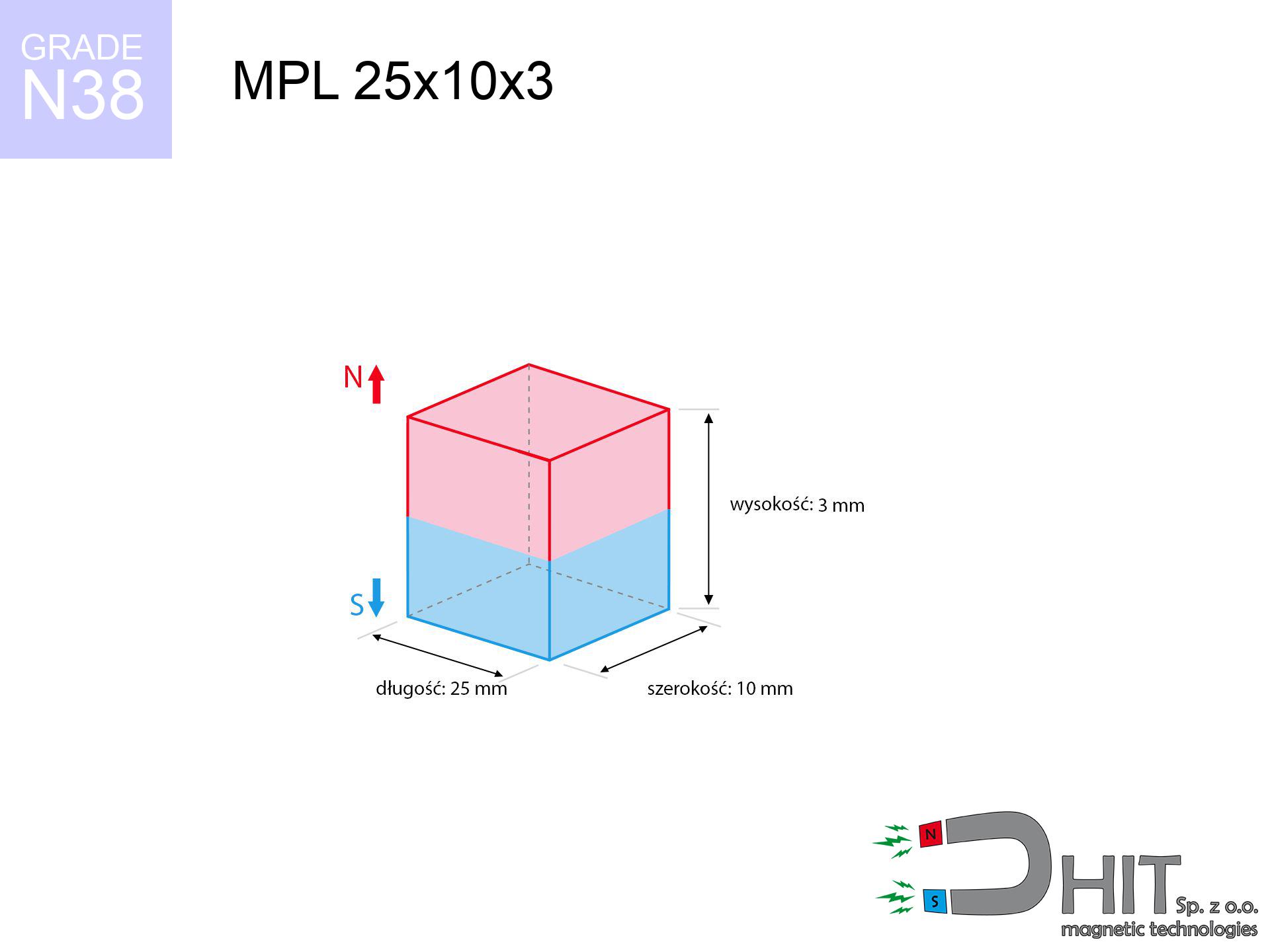
MPL 25x10x3 / N38 - lamellar magnet
lamellar magnet
Catalog no 020387
GTIN/EAN: 5906301811862
length
25 mm [±0,1 mm]
Width
10 mm [±0,1 mm]
Height
3 mm [±0,1 mm]
Weight
5.63 g
Magnetization Direction
↑ axial
Load capacity
4.14 kg / 40.56 N
Magnetic Induction
230.69 mT / 2307 Gs
Coating
[NiCuNi] Nickel
3.57 ZŁ with VAT / pcs + price for transport
2.90 ZŁ net + 23% VAT / pcs
bulk discounts:
Need more?
Give us a call
+48 888 99 98 98
otherwise let us know via
form
the contact section.
Parameters along with form of magnets can be reviewed on our
magnetic mass calculator.
Orders submitted before 14:00 will be dispatched today!
Product card - MPL 25x10x3 / N38 - lamellar magnet
Specification / characteristics - MPL 25x10x3 / N38 - lamellar magnet
| properties | values |
|---|---|
| Cat. no. | 020387 |
| GTIN/EAN | 5906301811862 |
| Production/Distribution | Dhit sp. z o.o. |
| Country of origin | Poland / China / Germany |
| Customs code | 85059029 |
| length | 25 mm [±0,1 mm] |
| Width | 10 mm [±0,1 mm] |
| Height | 3 mm [±0,1 mm] |
| Weight | 5.63 g |
| Magnetization Direction | ↑ axial |
| Load capacity ~ ? | 4.14 kg / 40.56 N |
| Magnetic Induction ~ ? | 230.69 mT / 2307 Gs |
| Coating | [NiCuNi] Nickel |
| Manufacturing Tolerance | ±0.1 mm |
Magnetic properties of material N38
| properties | values | units |
|---|---|---|
| remenance Br [min. - max.] ? | 12.2-12.6 | kGs |
| remenance Br [min. - max.] ? | 1220-1260 | mT |
| coercivity bHc ? | 10.8-11.5 | kOe |
| coercivity bHc ? | 860-915 | kA/m |
| actual internal force iHc | ≥ 12 | kOe |
| actual internal force iHc | ≥ 955 | kA/m |
| energy density [min. - max.] ? | 36-38 | BH max MGOe |
| energy density [min. - max.] ? | 287-303 | BH max KJ/m |
| max. temperature ? | ≤ 80 | °C |
Physical properties of sintered neodymium magnets Nd2Fe14B at 20°C
| properties | values | units |
|---|---|---|
| Vickers hardness | ≥550 | Hv |
| Density | ≥7.4 | g/cm3 |
| Curie Temperature TC | 312 - 380 | °C |
| Curie Temperature TF | 593 - 716 | °F |
| Specific resistance | 150 | μΩ⋅cm |
| Bending strength | 250 | MPa |
| Compressive strength | 1000~1100 | MPa |
| Thermal expansion parallel (∥) to orientation (M) | (3-4) x 10-6 | °C-1 |
| Thermal expansion perpendicular (⊥) to orientation (M) | -(1-3) x 10-6 | °C-1 |
| Young's modulus | 1.7 x 10⁴ | kg/mm² |
Engineering analysis of the product - report
The following data are the result of a engineering simulation. Values are based on algorithms for the material Nd2Fe14B. Actual conditions might slightly differ. Please consider these calculations as a preliminary roadmap during assembly planning.
Table 1: Static force (force vs gap) - characteristics
MPL 25x10x3 / N38
| Distance (mm) | Induction (Gauss) / mT | Pull Force (kg/lbs/g/N) | Risk Status |
|---|---|---|---|
| 0 mm |
2306 Gs
230.6 mT
|
4.14 kg / 9.13 lbs
4140.0 g / 40.6 N
|
medium risk |
| 1 mm |
2050 Gs
205.0 mT
|
3.27 kg / 7.21 lbs
3272.4 g / 32.1 N
|
medium risk |
| 2 mm |
1752 Gs
175.2 mT
|
2.39 kg / 5.27 lbs
2388.9 g / 23.4 N
|
medium risk |
| 3 mm |
1463 Gs
146.3 mT
|
1.67 kg / 3.68 lbs
1667.1 g / 16.4 N
|
safe |
| 5 mm |
1000 Gs
100.0 mT
|
0.78 kg / 1.72 lbs
779.2 g / 7.6 N
|
safe |
| 10 mm |
416 Gs
41.6 mT
|
0.13 kg / 0.30 lbs
134.4 g / 1.3 N
|
safe |
| 15 mm |
200 Gs
20.0 mT
|
0.03 kg / 0.07 lbs
31.0 g / 0.3 N
|
safe |
| 20 mm |
108 Gs
10.8 mT
|
0.01 kg / 0.02 lbs
9.0 g / 0.1 N
|
safe |
| 30 mm |
40 Gs
4.0 mT
|
0.00 kg / 0.00 lbs
1.3 g / 0.0 N
|
safe |
| 50 mm |
10 Gs
1.0 mT
|
0.00 kg / 0.00 lbs
0.1 g / 0.0 N
|
safe |
Table 2: Sliding hold (wall)
MPL 25x10x3 / N38
| Distance (mm) | Friction coefficient | Pull Force (kg/lbs/g/N) |
|---|---|---|
| 0 mm | Stal (~0.2) |
0.83 kg / 1.83 lbs
828.0 g / 8.1 N
|
| 1 mm | Stal (~0.2) |
0.65 kg / 1.44 lbs
654.0 g / 6.4 N
|
| 2 mm | Stal (~0.2) |
0.48 kg / 1.05 lbs
478.0 g / 4.7 N
|
| 3 mm | Stal (~0.2) |
0.33 kg / 0.74 lbs
334.0 g / 3.3 N
|
| 5 mm | Stal (~0.2) |
0.16 kg / 0.34 lbs
156.0 g / 1.5 N
|
| 10 mm | Stal (~0.2) |
0.03 kg / 0.06 lbs
26.0 g / 0.3 N
|
| 15 mm | Stal (~0.2) |
0.01 kg / 0.01 lbs
6.0 g / 0.1 N
|
| 20 mm | Stal (~0.2) |
0.00 kg / 0.00 lbs
2.0 g / 0.0 N
|
| 30 mm | Stal (~0.2) |
0.00 kg / 0.00 lbs
0.0 g / 0.0 N
|
| 50 mm | Stal (~0.2) |
0.00 kg / 0.00 lbs
0.0 g / 0.0 N
|
Table 3: Wall mounting (shearing) - vertical pull
MPL 25x10x3 / N38
| Surface type | Friction coefficient / % Mocy | Max load (kg/lbs/g/N) |
|---|---|---|
| Raw steel |
µ = 0.3
30% Nominalnej Siły
|
1.24 kg / 2.74 lbs
1242.0 g / 12.2 N
|
| Painted steel (standard) |
µ = 0.2
20% Nominalnej Siły
|
0.83 kg / 1.83 lbs
828.0 g / 8.1 N
|
| Oily/slippery steel |
µ = 0.1
10% Nominalnej Siły
|
0.41 kg / 0.91 lbs
414.0 g / 4.1 N
|
| Magnet with anti-slip rubber |
µ = 0.5
50% Nominalnej Siły
|
2.07 kg / 4.56 lbs
2070.0 g / 20.3 N
|
Table 4: Material efficiency (saturation) - sheet metal selection
MPL 25x10x3 / N38
| Steel thickness (mm) | % power | Real pull force (kg/lbs/g/N) |
|---|---|---|
| 0.5 mm |
|
0.41 kg / 0.91 lbs
414.0 g / 4.1 N
|
| 1 mm |
|
1.04 kg / 2.28 lbs
1035.0 g / 10.2 N
|
| 2 mm |
|
2.07 kg / 4.56 lbs
2070.0 g / 20.3 N
|
| 3 mm |
|
3.10 kg / 6.85 lbs
3105.0 g / 30.5 N
|
| 5 mm |
|
4.14 kg / 9.13 lbs
4140.0 g / 40.6 N
|
| 10 mm |
|
4.14 kg / 9.13 lbs
4140.0 g / 40.6 N
|
| 11 mm |
|
4.14 kg / 9.13 lbs
4140.0 g / 40.6 N
|
| 12 mm |
|
4.14 kg / 9.13 lbs
4140.0 g / 40.6 N
|
Table 5: Working in heat (stability) - thermal limit
MPL 25x10x3 / N38
| Ambient temp. (°C) | Power loss | Remaining pull (kg/lbs/g/N) | Status |
|---|---|---|---|
| 20 °C | 0.0% |
4.14 kg / 9.13 lbs
4140.0 g / 40.6 N
|
OK |
| 40 °C | -2.2% |
4.05 kg / 8.93 lbs
4048.9 g / 39.7 N
|
OK |
| 60 °C | -4.4% |
3.96 kg / 8.73 lbs
3957.8 g / 38.8 N
|
|
| 80 °C | -6.6% |
3.87 kg / 8.52 lbs
3866.8 g / 37.9 N
|
|
| 100 °C | -28.8% |
2.95 kg / 6.50 lbs
2947.7 g / 28.9 N
|
Table 6: Two magnets (repulsion) - field range
MPL 25x10x3 / N38
| Gap (mm) | Attraction (kg/lbs) (N-S) | Shear Strength (kg/lbs/g/N) | Repulsion (kg/lbs) (N-N) |
|---|---|---|---|
| 0 mm |
8.20 kg / 18.07 lbs
3 767 Gs
|
1.23 kg / 2.71 lbs
1230 g / 12.1 N
|
N/A |
| 1 mm |
7.38 kg / 16.27 lbs
4 377 Gs
|
1.11 kg / 2.44 lbs
1107 g / 10.9 N
|
6.64 kg / 14.65 lbs
~0 Gs
|
| 2 mm |
6.48 kg / 14.28 lbs
4 101 Gs
|
0.97 kg / 2.14 lbs
972 g / 9.5 N
|
5.83 kg / 12.86 lbs
~0 Gs
|
| 3 mm |
5.58 kg / 12.30 lbs
3 805 Gs
|
0.84 kg / 1.84 lbs
837 g / 8.2 N
|
5.02 kg / 11.07 lbs
~0 Gs
|
| 5 mm |
3.97 kg / 8.74 lbs
3 208 Gs
|
0.59 kg / 1.31 lbs
595 g / 5.8 N
|
3.57 kg / 7.87 lbs
~0 Gs
|
| 10 mm |
1.54 kg / 3.40 lbs
2 001 Gs
|
0.23 kg / 0.51 lbs
231 g / 2.3 N
|
1.39 kg / 3.06 lbs
~0 Gs
|
| 20 mm |
0.27 kg / 0.59 lbs
831 Gs
|
0.04 kg / 0.09 lbs
40 g / 0.4 N
|
0.24 kg / 0.53 lbs
~0 Gs
|
| 50 mm |
0.01 kg / 0.01 lbs
127 Gs
|
0.00 kg / 0.00 lbs
1 g / 0.0 N
|
0.00 kg / 0.00 lbs
~0 Gs
|
| 60 mm |
0.00 kg / 0.01 lbs
80 Gs
|
0.00 kg / 0.00 lbs
0 g / 0.0 N
|
0.00 kg / 0.00 lbs
~0 Gs
|
| 70 mm |
0.00 kg / 0.00 lbs
54 Gs
|
0.00 kg / 0.00 lbs
0 g / 0.0 N
|
0.00 kg / 0.00 lbs
~0 Gs
|
| 80 mm |
0.00 kg / 0.00 lbs
38 Gs
|
0.00 kg / 0.00 lbs
0 g / 0.0 N
|
0.00 kg / 0.00 lbs
~0 Gs
|
| 90 mm |
0.00 kg / 0.00 lbs
27 Gs
|
0.00 kg / 0.00 lbs
0 g / 0.0 N
|
0.00 kg / 0.00 lbs
~0 Gs
|
| 100 mm |
0.00 kg / 0.00 lbs
20 Gs
|
0.00 kg / 0.00 lbs
0 g / 0.0 N
|
0.00 kg / 0.00 lbs
~0 Gs
|
Table 7: Protective zones (implants) - warnings
MPL 25x10x3 / N38
| Object / Device | Limit (Gauss) / mT | Safe distance |
|---|---|---|
| Pacemaker | 5 Gs (0.5 mT) | 6.5 cm |
| Hearing aid | 10 Gs (1.0 mT) | 5.5 cm |
| Mechanical watch | 20 Gs (2.0 mT) | 4.0 cm |
| Mobile device | 40 Gs (4.0 mT) | 3.5 cm |
| Remote | 50 Gs (5.0 mT) | 3.0 cm |
| Payment card | 400 Gs (40.0 mT) | 1.5 cm |
| HDD hard drive | 600 Gs (60.0 mT) | 1.0 cm |
Table 8: Dynamics (cracking risk) - collision effects
MPL 25x10x3 / N38
| Start from (mm) | Speed (km/h) | Energy (J) | Predicted outcome |
|---|---|---|---|
| 10 mm |
27.90 km/h
(7.75 m/s)
|
0.17 J | |
| 30 mm |
47.38 km/h
(13.16 m/s)
|
0.49 J | |
| 50 mm |
61.15 km/h
(16.99 m/s)
|
0.81 J | |
| 100 mm |
86.48 km/h
(24.02 m/s)
|
1.62 J |
Table 9: Anti-corrosion coating durability
MPL 25x10x3 / N38
| Technical parameter | Value / Description |
|---|---|
| Coating type | [NiCuNi] Nickel |
| Layer structure | Nickel - Copper - Nickel |
| Layer thickness | 10-20 µm |
| Salt spray test (SST) ? | 24 h |
| Recommended environment | Indoors only (dry) |
Table 10: Construction data (Flux)
MPL 25x10x3 / N38
| Parameter | Value | SI Unit / Description |
|---|---|---|
| Magnetic Flux | 5 928 Mx | 59.3 µWb |
| Pc Coefficient | 0.25 | Low (Flat) |
Table 11: Physics of underwater searching
MPL 25x10x3 / N38
| Environment | Effective steel pull | Effect |
|---|---|---|
| Air (land) | 4.14 kg | Standard |
| Water (riverbed) |
4.74 kg
(+0.60 kg buoyancy gain)
|
+14.5% |
1. Vertical hold
*Caution: On a vertical wall, the magnet retains merely ~20% of its perpendicular strength.
2. Efficiency vs thickness
*Thin metal sheet (e.g. 0.5mm PC case) drastically weakens the holding force.
3. Heat tolerance
*For N38 material, the max working temp is 80°C.
4. Demagnetization curve and operating point (B-H)
chart generated for the permeance coefficient Pc (Permeance Coefficient) = 0.25
This simulation demonstrates the magnetic stability of the selected magnet under specific geometric conditions. The solid red line represents the demagnetization curve (material potential), while the dashed blue line is the load line based on the magnet's geometry. The Pc (Permeance Coefficient), also known as the load line slope, is a dimensionless value that describes the relationship between the magnet's shape and its magnetic stability. The intersection of these two lines (the black dot) is the operating point — it determines the actual magnetic flux density generated by the magnet in this specific configuration. A higher Pc value means the magnet is more 'slender' (tall relative to its area), resulting in a higher operating point and better resistance to irreversible demagnetization caused by external fields or temperature. A value of 0.42 is relatively low (typical for flat magnets), meaning the operating point is closer to the 'knee' of the curve — caution is advised when operating at temperatures near the maximum limit to avoid strength loss.
Chemical composition
| iron (Fe) | 64% – 68% |
| neodymium (Nd) | 29% – 32% |
| boron (B) | 1.1% – 1.2% |
| dysprosium (Dy) | 0.5% – 2.0% |
| coating (Ni-Cu-Ni) | < 0.05% |
Ecology and recycling (GPSR)
| recyclability (EoL) | 100% |
| recycled raw materials | ~10% (pre-cons) |
| carbon footprint | low / zredukowany |
| waste code (EWC) | 16 02 16 |
Check out more offers
![UMGGW 66x8.5 [M8] GW / N38 - magnetic holder rubber internal thread](https://cdn3.dhit.pl/graphics/products/umg-66x8.5-m6-gw-wud.jpg "UMGGW 66x8.5 [M8] GW / N38 - magnetic holder rubber internal thread")
![UMGW 42x20x9 [M6] GW / N38 - magnetic holder internal thread](https://cdn3.dhit.pl/graphics/products/um-42x20x9-m8-gw-god.jpg "UMGW 42x20x9 [M6] GW / N38 - magnetic holder internal thread")


Pros as well as cons of Nd2Fe14B magnets.
Benefits
- Their strength is durable, and after approximately ten years it decreases only by ~1% (theoretically),
- They feature excellent resistance to magnetic field loss when exposed to external magnetic sources,
- In other words, due to the smooth finish of silver, the element becomes visually attractive,
- Neodymium magnets create maximum magnetic induction on a small area, which increases force concentration,
- Neodymium magnets are characterized by extremely high magnetic induction on the magnet surface and are able to act (depending on the form) even at a temperature of 230°C or more...
- Thanks to flexibility in constructing and the ability to modify to complex applications,
- Universal use in innovative solutions – they serve a role in mass storage devices, brushless drives, advanced medical instruments, as well as multitasking production systems.
- Relatively small size with high pulling force – neodymium magnets offer high power in small dimensions, which makes them useful in compact constructions
Limitations
- To avoid cracks under impact, we recommend using special steel holders. Such a solution secures the magnet and simultaneously improves its durability.
- We warn that neodymium magnets can lose their power at high temperatures. To prevent this, we recommend our specialized [AH] magnets, which work effectively even at 230°C.
- Magnets exposed to a humid environment can corrode. Therefore while using outdoors, we suggest using waterproof magnets made of rubber, plastic or other material protecting against moisture
- Due to limitations in realizing threads and complicated forms in magnets, we propose using cover - magnetic mount.
- Health risk to health – tiny shards of magnets pose a threat, if swallowed, which gains importance in the aspect of protecting the youngest. Furthermore, small elements of these magnets are able to disrupt the diagnostic process medical when they are in the body.
- Higher cost of purchase is a significant factor to consider compared to ceramic magnets, especially in budget applications
Lifting parameters
Maximum holding power of the magnet – what it depends on?
- using a plate made of high-permeability steel, serving as a ideal flux conductor
- possessing a massiveness of minimum 10 mm to avoid saturation
- characterized by lack of roughness
- under conditions of no distance (surface-to-surface)
- during detachment in a direction vertical to the mounting surface
- at standard ambient temperature
Practical aspects of lifting capacity – factors
- Clearance – the presence of any layer (rust, tape, air) acts as an insulator, which lowers capacity steeply (even by 50% at 0.5 mm).
- Pull-off angle – remember that the magnet has greatest strength perpendicularly. Under shear forces, the capacity drops drastically, often to levels of 20-30% of the maximum value.
- Element thickness – for full efficiency, the steel must be sufficiently thick. Paper-thin metal limits the attraction force (the magnet "punches through" it).
- Metal type – not every steel attracts identically. High carbon content weaken the interaction with the magnet.
- Surface finish – ideal contact is possible only on polished steel. Rough texture create air cushions, weakening the magnet.
- Temperature – temperature increase causes a temporary drop of force. It is worth remembering the maximum operating temperature for a given model.
Holding force was checked on a smooth steel plate of 20 mm thickness, when the force acted perpendicularly, however under shearing force the lifting capacity is smaller. Moreover, even a minimal clearance between the magnet and the plate decreases the lifting capacity.
H&S for magnets
Safe distance
Powerful magnetic fields can erase data on payment cards, HDDs, and storage devices. Stay away of min. 10 cm.
Precision electronics
GPS units and mobile phones are highly susceptible to magnetism. Close proximity with a strong magnet can ruin the sensors in your phone.
Bodily injuries
Mind your fingers. Two powerful magnets will join immediately with a force of several hundred kilograms, crushing anything in their path. Be careful!
Choking Hazard
Absolutely keep magnets away from children. Ingestion danger is high, and the consequences of magnets clamping inside the body are very dangerous.
Warning for allergy sufferers
Medical facts indicate that nickel (standard magnet coating) is a common allergen. For allergy sufferers, prevent direct skin contact and choose coated magnets.
Fragile material
Despite the nickel coating, neodymium is brittle and cannot withstand shocks. Do not hit, as the magnet may shatter into sharp, dangerous pieces.
Do not drill into magnets
Fire warning: Rare earth powder is highly flammable. Do not process magnets without safety gear as this may cause fire.
Do not overheat magnets
Monitor thermal conditions. Exposing the magnet above 80 degrees Celsius will ruin its magnetic structure and strength.
Immense force
Use magnets with awareness. Their huge power can shock even professionals. Stay alert and do not underestimate their power.
Danger to pacemakers
Patients with a heart stimulator should maintain an safe separation from magnets. The magnetic field can disrupt the functioning of the life-saving device.
Tabela kosztu i czasu dostawy
Płatność przed wysyłką:

GLS kurier
Przesyłka będzie u Ciebie za 2-3 dni
14.99 ZŁ

InPost Paczkomaty 24/7
Przesyłka będzie u Ciebie za 1-2 dni
12.30 ZŁ
Płatność przy odbiorze (pobranie):
GLS kurier
Przesyłka będzie u Ciebie za 1-2 dni
23.00 ZŁ
Rate the product
Your rating