
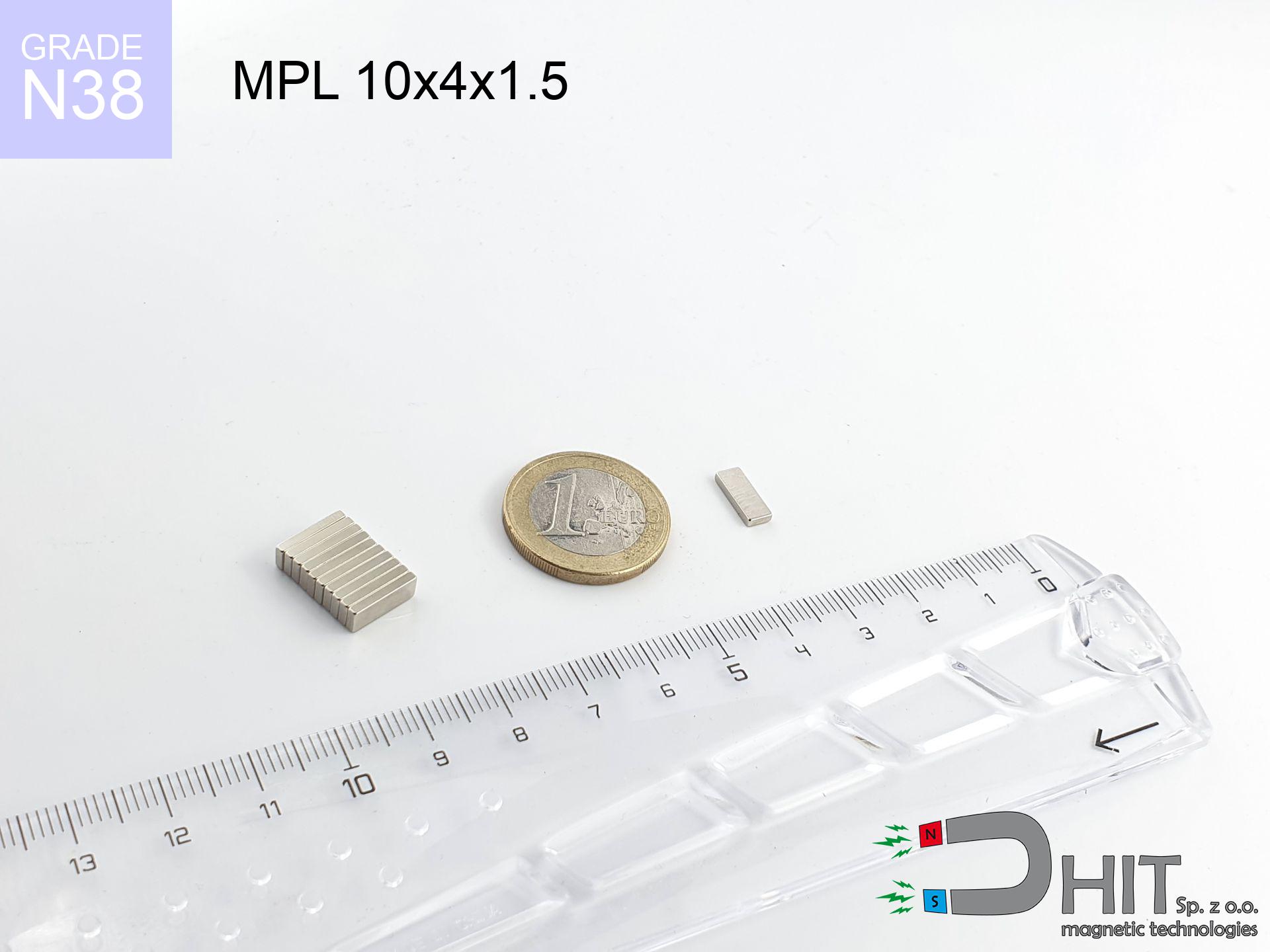

MPL 10x4x1.5 / N38 - lamellar magnet
lamellar magnet
Catalog no 020113
GTIN/EAN: 5906301811190
length
10 mm [±0,1 mm]
Width
4 mm [±0,1 mm]
Height
1.5 mm [±0,1 mm]
Weight
0.45 g
Magnetization Direction
↑ axial
Load capacity
0.88 kg / 8.65 N
Magnetic Induction
274.96 mT / 2750 Gs
Coating
[NiCuNi] Nickel
0.246 ZŁ with VAT / pcs + price for transport
0.200 ZŁ net + 23% VAT / pcs
bulk discounts:
Need more?
Pick up the phone and ask
+48 22 499 98 98
or send us a note through
inquiry form
the contact page.
Lifting power along with appearance of neodymium magnets can be reviewed on our
magnetic calculator.
Orders placed before 14:00 will be shipped the same business day.
Technical specification of the product - MPL 10x4x1.5 / N38 - lamellar magnet
Specification / characteristics - MPL 10x4x1.5 / N38 - lamellar magnet
| properties | values |
|---|---|
| Cat. no. | 020113 |
| GTIN/EAN | 5906301811190 |
| Production/Distribution | Dhit sp. z o.o. |
| Country of origin | Poland / China / Germany |
| Customs code | 85059029 |
| length | 10 mm [±0,1 mm] |
| Width | 4 mm [±0,1 mm] |
| Height | 1.5 mm [±0,1 mm] |
| Weight | 0.45 g |
| Magnetization Direction | ↑ axial |
| Load capacity ~ ? | 0.88 kg / 8.65 N |
| Magnetic Induction ~ ? | 274.96 mT / 2750 Gs |
| Coating | [NiCuNi] Nickel |
| Manufacturing Tolerance | ±0.1 mm |
Magnetic properties of material N38
| properties | values | units |
|---|---|---|
| remenance Br [min. - max.] ? | 12.2-12.6 | kGs |
| remenance Br [min. - max.] ? | 1220-1260 | mT |
| coercivity bHc ? | 10.8-11.5 | kOe |
| coercivity bHc ? | 860-915 | kA/m |
| actual internal force iHc | ≥ 12 | kOe |
| actual internal force iHc | ≥ 955 | kA/m |
| energy density [min. - max.] ? | 36-38 | BH max MGOe |
| energy density [min. - max.] ? | 287-303 | BH max KJ/m |
| max. temperature ? | ≤ 80 | °C |
Physical properties of sintered neodymium magnets Nd2Fe14B at 20°C
| properties | values | units |
|---|---|---|
| Vickers hardness | ≥550 | Hv |
| Density | ≥7.4 | g/cm3 |
| Curie Temperature TC | 312 - 380 | °C |
| Curie Temperature TF | 593 - 716 | °F |
| Specific resistance | 150 | μΩ⋅cm |
| Bending strength | 250 | MPa |
| Compressive strength | 1000~1100 | MPa |
| Thermal expansion parallel (∥) to orientation (M) | (3-4) x 10-6 | °C-1 |
| Thermal expansion perpendicular (⊥) to orientation (M) | -(1-3) x 10-6 | °C-1 |
| Young's modulus | 1.7 x 10⁴ | kg/mm² |
Engineering modeling of the magnet - data
The following information are the outcome of a mathematical simulation. Values are based on models for the class Nd2Fe14B. Real-world parameters may differ from theoretical values. Please consider these calculations as a reference point for designers.
Table 1: Static pull force (pull vs gap) - interaction chart
MPL 10x4x1.5 / N38
| Distance (mm) | Induction (Gauss) / mT | Pull Force (kg/lbs/g/N) | Risk Status |
|---|---|---|---|
| 0 mm |
2747 Gs
274.7 mT
|
0.88 kg / 1.94 pounds
880.0 g / 8.6 N
|
safe |
| 1 mm |
1882 Gs
188.2 mT
|
0.41 kg / 0.91 pounds
413.1 g / 4.1 N
|
safe |
| 2 mm |
1175 Gs
117.5 mT
|
0.16 kg / 0.35 pounds
161.0 g / 1.6 N
|
safe |
| 3 mm |
746 Gs
74.6 mT
|
0.06 kg / 0.14 pounds
64.9 g / 0.6 N
|
safe |
| 5 mm |
337 Gs
33.7 mT
|
0.01 kg / 0.03 pounds
13.3 g / 0.1 N
|
safe |
| 10 mm |
77 Gs
7.7 mT
|
0.00 kg / 0.00 pounds
0.7 g / 0.0 N
|
safe |
| 15 mm |
27 Gs
2.7 mT
|
0.00 kg / 0.00 pounds
0.1 g / 0.0 N
|
safe |
| 20 mm |
12 Gs
1.2 mT
|
0.00 kg / 0.00 pounds
0.0 g / 0.0 N
|
safe |
| 30 mm |
4 Gs
0.4 mT
|
0.00 kg / 0.00 pounds
0.0 g / 0.0 N
|
safe |
| 50 mm |
1 Gs
0.1 mT
|
0.00 kg / 0.00 pounds
0.0 g / 0.0 N
|
safe |
Table 2: Sliding force (vertical surface)
MPL 10x4x1.5 / N38
| Distance (mm) | Friction coefficient | Pull Force (kg/lbs/g/N) |
|---|---|---|
| 0 mm | Stal (~0.2) |
0.18 kg / 0.39 pounds
176.0 g / 1.7 N
|
| 1 mm | Stal (~0.2) |
0.08 kg / 0.18 pounds
82.0 g / 0.8 N
|
| 2 mm | Stal (~0.2) |
0.03 kg / 0.07 pounds
32.0 g / 0.3 N
|
| 3 mm | Stal (~0.2) |
0.01 kg / 0.03 pounds
12.0 g / 0.1 N
|
| 5 mm | Stal (~0.2) |
0.00 kg / 0.00 pounds
2.0 g / 0.0 N
|
| 10 mm | Stal (~0.2) |
0.00 kg / 0.00 pounds
0.0 g / 0.0 N
|
| 15 mm | Stal (~0.2) |
0.00 kg / 0.00 pounds
0.0 g / 0.0 N
|
| 20 mm | Stal (~0.2) |
0.00 kg / 0.00 pounds
0.0 g / 0.0 N
|
| 30 mm | Stal (~0.2) |
0.00 kg / 0.00 pounds
0.0 g / 0.0 N
|
| 50 mm | Stal (~0.2) |
0.00 kg / 0.00 pounds
0.0 g / 0.0 N
|
Table 3: Wall mounting (shearing) - vertical pull
MPL 10x4x1.5 / N38
| Surface type | Friction coefficient / % Mocy | Max load (kg/lbs/g/N) |
|---|---|---|
| Raw steel |
µ = 0.3
30% Nominalnej Siły
|
0.26 kg / 0.58 pounds
264.0 g / 2.6 N
|
| Painted steel (standard) |
µ = 0.2
20% Nominalnej Siły
|
0.18 kg / 0.39 pounds
176.0 g / 1.7 N
|
| Oily/slippery steel |
µ = 0.1
10% Nominalnej Siły
|
0.09 kg / 0.19 pounds
88.0 g / 0.9 N
|
| Magnet with anti-slip rubber |
µ = 0.5
50% Nominalnej Siły
|
0.44 kg / 0.97 pounds
440.0 g / 4.3 N
|
Table 4: Steel thickness (substrate influence) - sheet metal selection
MPL 10x4x1.5 / N38
| Steel thickness (mm) | % power | Real pull force (kg/lbs/g/N) |
|---|---|---|
| 0.5 mm |
|
0.09 kg / 0.19 pounds
88.0 g / 0.9 N
|
| 1 mm |
|
0.22 kg / 0.49 pounds
220.0 g / 2.2 N
|
| 2 mm |
|
0.44 kg / 0.97 pounds
440.0 g / 4.3 N
|
| 3 mm |
|
0.66 kg / 1.46 pounds
660.0 g / 6.5 N
|
| 5 mm |
|
0.88 kg / 1.94 pounds
880.0 g / 8.6 N
|
| 10 mm |
|
0.88 kg / 1.94 pounds
880.0 g / 8.6 N
|
| 11 mm |
|
0.88 kg / 1.94 pounds
880.0 g / 8.6 N
|
| 12 mm |
|
0.88 kg / 1.94 pounds
880.0 g / 8.6 N
|
Table 5: Thermal stability (material behavior) - resistance threshold
MPL 10x4x1.5 / N38
| Ambient temp. (°C) | Power loss | Remaining pull (kg/lbs/g/N) | Status |
|---|---|---|---|
| 20 °C | 0.0% |
0.88 kg / 1.94 pounds
880.0 g / 8.6 N
|
OK |
| 40 °C | -2.2% |
0.86 kg / 1.90 pounds
860.6 g / 8.4 N
|
OK |
| 60 °C | -4.4% |
0.84 kg / 1.85 pounds
841.3 g / 8.3 N
|
|
| 80 °C | -6.6% |
0.82 kg / 1.81 pounds
821.9 g / 8.1 N
|
|
| 100 °C | -28.8% |
0.63 kg / 1.38 pounds
626.6 g / 6.1 N
|
Table 6: Two magnets (attraction) - field collision
MPL 10x4x1.5 / N38
| Gap (mm) | Attraction (kg/lbs) (N-S) | Shear Strength (kg/lbs/g/N) | Repulsion (kg/lbs) (N-N) |
|---|---|---|---|
| 0 mm |
1.86 kg / 4.10 pounds
4 229 Gs
|
0.28 kg / 0.62 pounds
279 g / 2.7 N
|
N/A |
| 1 mm |
1.34 kg / 2.95 pounds
4 661 Gs
|
0.20 kg / 0.44 pounds
201 g / 2.0 N
|
1.21 kg / 2.66 pounds
~0 Gs
|
| 2 mm |
0.87 kg / 1.93 pounds
3 764 Gs
|
0.13 kg / 0.29 pounds
131 g / 1.3 N
|
0.79 kg / 1.73 pounds
~0 Gs
|
| 3 mm |
0.55 kg / 1.21 pounds
2 978 Gs
|
0.08 kg / 0.18 pounds
82 g / 0.8 N
|
0.49 kg / 1.09 pounds
~0 Gs
|
| 5 mm |
0.21 kg / 0.47 pounds
1 864 Gs
|
0.03 kg / 0.07 pounds
32 g / 0.3 N
|
0.19 kg / 0.43 pounds
~0 Gs
|
| 10 mm |
0.03 kg / 0.06 pounds
675 Gs
|
0.00 kg / 0.01 pounds
4 g / 0.0 N
|
0.03 kg / 0.06 pounds
~0 Gs
|
| 20 mm |
0.00 kg / 0.00 pounds
154 Gs
|
0.00 kg / 0.00 pounds
0 g / 0.0 N
|
0.00 kg / 0.00 pounds
~0 Gs
|
| 50 mm |
0.00 kg / 0.00 pounds
13 Gs
|
0.00 kg / 0.00 pounds
0 g / 0.0 N
|
0.00 kg / 0.00 pounds
~0 Gs
|
| 60 mm |
0.00 kg / 0.00 pounds
8 Gs
|
0.00 kg / 0.00 pounds
0 g / 0.0 N
|
0.00 kg / 0.00 pounds
~0 Gs
|
| 70 mm |
0.00 kg / 0.00 pounds
5 Gs
|
0.00 kg / 0.00 pounds
0 g / 0.0 N
|
0.00 kg / 0.00 pounds
~0 Gs
|
| 80 mm |
0.00 kg / 0.00 pounds
3 Gs
|
0.00 kg / 0.00 pounds
0 g / 0.0 N
|
0.00 kg / 0.00 pounds
~0 Gs
|
| 90 mm |
0.00 kg / 0.00 pounds
2 Gs
|
0.00 kg / 0.00 pounds
0 g / 0.0 N
|
0.00 kg / 0.00 pounds
~0 Gs
|
| 100 mm |
0.00 kg / 0.00 pounds
2 Gs
|
0.00 kg / 0.00 pounds
0 g / 0.0 N
|
0.00 kg / 0.00 pounds
~0 Gs
|
Table 7: Safety (HSE) (electronics) - warnings
MPL 10x4x1.5 / N38
| Object / Device | Limit (Gauss) / mT | Safe distance |
|---|---|---|
| Pacemaker | 5 Gs (0.5 mT) | 3.0 cm |
| Hearing aid | 10 Gs (1.0 mT) | 2.5 cm |
| Timepiece | 20 Gs (2.0 mT) | 2.0 cm |
| Mobile device | 40 Gs (4.0 mT) | 1.5 cm |
| Car key | 50 Gs (5.0 mT) | 1.5 cm |
| Payment card | 400 Gs (40.0 mT) | 0.5 cm |
| HDD hard drive | 600 Gs (60.0 mT) | 0.5 cm |
Table 8: Collisions (cracking risk) - warning
MPL 10x4x1.5 / N38
| Start from (mm) | Speed (km/h) | Energy (J) | Predicted outcome |
|---|---|---|---|
| 10 mm |
44.62 km/h
(12.39 m/s)
|
0.03 J | |
| 30 mm |
77.25 km/h
(21.46 m/s)
|
0.10 J | |
| 50 mm |
99.72 km/h
(27.70 m/s)
|
0.17 J | |
| 100 mm |
141.03 km/h
(39.18 m/s)
|
0.35 J |
Table 9: Anti-corrosion coating durability
MPL 10x4x1.5 / N38
| Technical parameter | Value / Description |
|---|---|
| Coating type | [NiCuNi] Nickel |
| Layer structure | Nickel - Copper - Nickel |
| Layer thickness | 10-20 µm |
| Salt spray test (SST) ? | 24 h |
| Recommended environment | Indoors only (dry) |
Table 10: Construction data (Flux)
MPL 10x4x1.5 / N38
| Parameter | Value | SI Unit / Description |
|---|---|---|
| Magnetic Flux | 1 104 Mx | 11.0 µWb |
| Pc Coefficient | 0.30 | Low (Flat) |
Table 11: Physics of underwater searching
MPL 10x4x1.5 / N38
| Environment | Effective steel pull | Effect |
|---|---|---|
| Air (land) | 0.88 kg | Standard |
| Water (riverbed) |
1.01 kg
(+0.13 kg buoyancy gain)
|
+14.5% |
1. Wall mount (shear)
*Warning: On a vertical surface, the magnet retains merely approx. 20-30% of its perpendicular strength.
2. Efficiency vs thickness
*Thin steel (e.g. computer case) severely weakens the holding force.
3. Heat tolerance
*For standard magnets, the max working temp is 80°C.
4. Demagnetization curve and operating point (B-H)
chart generated for the permeance coefficient Pc (Permeance Coefficient) = 0.30
This simulation demonstrates the magnetic stability of the selected magnet under specific geometric conditions. The solid red line represents the demagnetization curve (material potential), while the dashed blue line is the load line based on the magnet's geometry. The Pc (Permeance Coefficient), also known as the load line slope, is a dimensionless value that describes the relationship between the magnet's shape and its magnetic stability. The intersection of these two lines (the black dot) is the operating point — it determines the actual magnetic flux density generated by the magnet in this specific configuration. A higher Pc value means the magnet is more 'slender' (tall relative to its area), resulting in a higher operating point and better resistance to irreversible demagnetization caused by external fields or temperature. A value of 0.42 is relatively low (typical for flat magnets), meaning the operating point is closer to the 'knee' of the curve — caution is advised when operating at temperatures near the maximum limit to avoid strength loss.
Elemental analysis
| iron (Fe) | 64% – 68% |
| neodymium (Nd) | 29% – 32% |
| boron (B) | 1.1% – 1.2% |
| dysprosium (Dy) | 0.5% – 2.0% |
| coating (Ni-Cu-Ni) | < 0.05% |
Sustainability
| recyclability (EoL) | 100% |
| recycled raw materials | ~10% (pre-cons) |
| carbon footprint | low / zredukowany |
| waste code (EWC) | 16 02 16 |
Check out more offers

![UMGGW 34x8 [M4] GW / N38 - magnetic holder rubber internal thread](https://cdn3.dhit.pl/graphics/products/umg-34x8-m4-gw-kek.jpg "UMGGW 34x8 [M4] GW / N38 - magnetic holder rubber internal thread")
![SM 32x475 [2xM8] / N42 - magnetic separator](https://cdn3.dhit.pl/graphics/products/sm-32x475-2xm8-jot.jpg "SM 32x475 [2xM8] / N42 - magnetic separator")

Strengths and weaknesses of Nd2Fe14B magnets.
Strengths
- Their strength is durable, and after approximately 10 years it decreases only by ~1% (according to research),
- They are resistant to demagnetization induced by external disturbances,
- Thanks to the metallic finish, the coating of nickel, gold, or silver-plated gives an clean appearance,
- They are known for high magnetic induction at the operating surface, which affects their effectiveness,
- Through (appropriate) combination of ingredients, they can achieve high thermal strength, allowing for functioning at temperatures reaching 230°C and above...
- In view of the option of flexible molding and adaptation to unique requirements, magnetic components can be manufactured in a wide range of forms and dimensions, which expands the range of possible applications,
- Key role in high-tech industry – they are utilized in hard drives, electromotive mechanisms, advanced medical instruments, as well as multitasking production systems.
- Thanks to efficiency per cm³, small magnets offer high operating force, in miniature format,
Limitations
- They are prone to damage upon heavy impacts. To avoid cracks, it is worth protecting magnets in a protective case. Such protection not only shields the magnet but also increases its resistance to damage
- NdFeB magnets lose power when exposed to high temperatures. After reaching 80°C, many of them experience permanent weakening of power (a factor is the shape as well as dimensions of the magnet). We offer magnets specially adapted to work at temperatures up to 230°C marked [AH], which are extremely resistant to heat
- Magnets exposed to a humid environment can corrode. Therefore during using outdoors, we advise using waterproof magnets made of rubber, plastic or other material resistant to moisture
- We recommend casing - magnetic holder, due to difficulties in producing threads inside the magnet and complex forms.
- Potential hazard resulting from small fragments of magnets pose a threat, if swallowed, which becomes key in the context of child safety. Additionally, tiny parts of these magnets are able to be problematic in diagnostics medical after entering the body.
- High unit price – neodymium magnets are more expensive than other types of magnets (e.g. ferrite), which can limit application in large quantities
Holding force characteristics
Maximum lifting capacity of the magnet – what contributes to it?
- on a plate made of structural steel, effectively closing the magnetic field
- possessing a massiveness of minimum 10 mm to avoid saturation
- characterized by even structure
- without the slightest insulating layer between the magnet and steel
- under vertical force vector (90-degree angle)
- in stable room temperature
Lifting capacity in real conditions – factors
- Gap between magnet and steel – every millimeter of separation (caused e.g. by varnish or dirt) drastically reduces the magnet efficiency, often by half at just 0.5 mm.
- Direction of force – highest force is reached only during pulling at a 90° angle. The resistance to sliding of the magnet along the surface is typically many times smaller (approx. 1/5 of the lifting capacity).
- Metal thickness – thin material does not allow full use of the magnet. Part of the magnetic field passes through the material instead of converting into lifting capacity.
- Steel grade – ideal substrate is high-permeability steel. Stainless steels may generate lower lifting capacity.
- Plate texture – smooth surfaces guarantee perfect abutment, which increases field saturation. Rough surfaces weaken the grip.
- Thermal environment – heating the magnet results in weakening of induction. Check the thermal limit for a given model.
Holding force was tested on a smooth steel plate of 20 mm thickness, when the force acted perpendicularly, however under attempts to slide the magnet the lifting capacity is smaller. Additionally, even a slight gap between the magnet’s surface and the plate reduces the lifting capacity.
H&S for magnets
Operating temperature
Keep cool. Neodymium magnets are susceptible to temperature. If you need operation above 80°C, inquire about special high-temperature series (H, SH, UH).
Protective goggles
Despite the nickel coating, the material is brittle and cannot withstand shocks. Do not hit, as the magnet may crumble into hazardous fragments.
Physical harm
Mind your fingers. Two powerful magnets will snap together immediately with a force of several hundred kilograms, crushing everything in their path. Be careful!
Allergy Warning
Some people experience a contact allergy to nickel, which is the common plating for neodymium magnets. Prolonged contact can result in skin redness. We strongly advise wear protective gloves.
Phone sensors
An intense magnetic field disrupts the operation of compasses in smartphones and navigation systems. Do not bring magnets near a device to prevent breaking the sensors.
Magnetic media
Intense magnetic fields can erase data on payment cards, hard drives, and storage devices. Keep a distance of at least 10 cm.
Caution required
Handle with care. Rare earth magnets act from a long distance and connect with huge force, often faster than you can react.
Choking Hazard
NdFeB magnets are not suitable for play. Accidental ingestion of a few magnets may result in them attracting across intestines, which poses a critical condition and requires urgent medical intervention.
Dust is flammable
Machining of neodymium magnets poses a fire hazard. Neodymium dust oxidizes rapidly with oxygen and is difficult to extinguish.
Implant safety
Individuals with a heart stimulator should maintain an absolute distance from magnets. The magnetism can disrupt the operation of the life-saving device.
Tabela kosztu i czasu dostawy
Płatność przed wysyłką:

GLS kurier
Przesyłka będzie u Ciebie za 2-3 dni
14.99 ZŁ

InPost Paczkomaty 24/7
Przesyłka będzie u Ciebie za 1-2 dni
12.30 ZŁ
Płatność przy odbiorze (pobranie):
GLS kurier
Przesyłka będzie u Ciebie za 1-2 dni
23.00 ZŁ
Rate the product
Your rating