

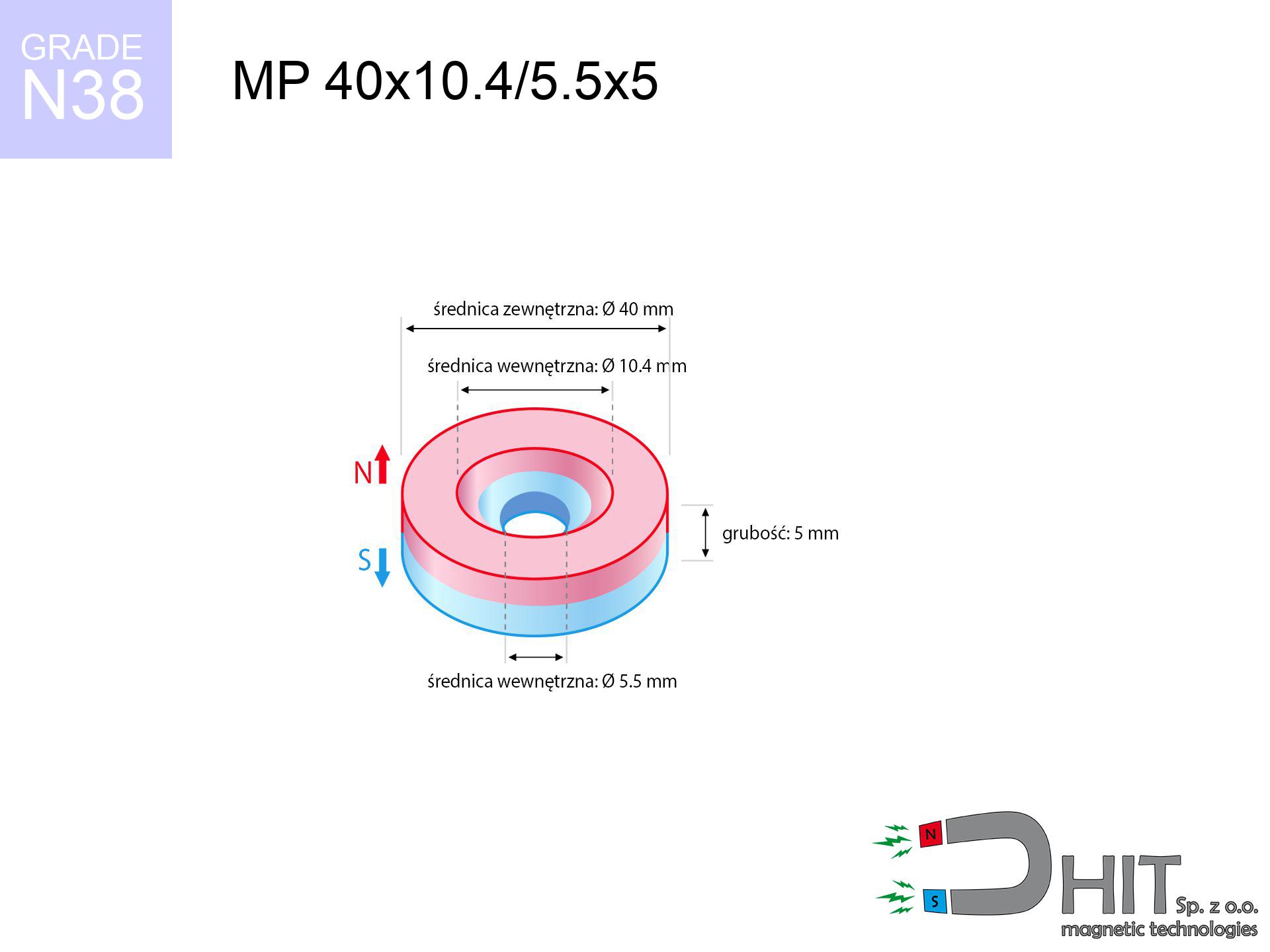
MP 40x10.4/5.5x5 / N38 - ring magnet
ring magnet
Catalog no 030249
GTIN/EAN: 5906301812258
Diameter
40 mm [±0,1 mm]
internal diameter Ø
10.4/5.5 mm [±0,1 mm]
Height
5 mm [±0,1 mm]
Weight
46.23 g
Magnetization Direction
↑ axial
Load capacity
9.47 kg / 92.86 N
Magnetic Induction
150.36 mT / 1504 Gs
Coating
[NiCuNi] Nickel
27.00 ZŁ with VAT / pcs + price for transport
21.95 ZŁ net + 23% VAT / pcs
bulk discounts:
Need more?
Call us now
+48 888 99 98 98
otherwise send us a note using
contact form
the contact section.
Parameters as well as appearance of a neodymium magnet can be tested on our
our magnetic calculator.
Order by 14:00 and we’ll ship today!
Product card - MP 40x10.4/5.5x5 / N38 - ring magnet
Specification / characteristics - MP 40x10.4/5.5x5 / N38 - ring magnet
| properties | values |
|---|---|
| Cat. no. | 030249 |
| GTIN/EAN | 5906301812258 |
| Production/Distribution | Dhit sp. z o.o. |
| Country of origin | Poland / China / Germany |
| Customs code | 85059029 |
| Diameter | 40 mm [±0,1 mm] |
| internal diameter Ø | 10.4/5.5 mm [±0,1 mm] |
| Height | 5 mm [±0,1 mm] |
| Weight | 46.23 g |
| Magnetization Direction | ↑ axial |
| Load capacity ~ ? | 9.47 kg / 92.86 N |
| Magnetic Induction ~ ? | 150.36 mT / 1504 Gs |
| Coating | [NiCuNi] Nickel |
| Manufacturing Tolerance | ±0.1 mm |
Magnetic properties of material N38
| properties | values | units |
|---|---|---|
| remenance Br [min. - max.] ? | 12.2-12.6 | kGs |
| remenance Br [min. - max.] ? | 1220-1260 | mT |
| coercivity bHc ? | 10.8-11.5 | kOe |
| coercivity bHc ? | 860-915 | kA/m |
| actual internal force iHc | ≥ 12 | kOe |
| actual internal force iHc | ≥ 955 | kA/m |
| energy density [min. - max.] ? | 36-38 | BH max MGOe |
| energy density [min. - max.] ? | 287-303 | BH max KJ/m |
| max. temperature ? | ≤ 80 | °C |
Physical properties of sintered neodymium magnets Nd2Fe14B at 20°C
| properties | values | units |
|---|---|---|
| Vickers hardness | ≥550 | Hv |
| Density | ≥7.4 | g/cm3 |
| Curie Temperature TC | 312 - 380 | °C |
| Curie Temperature TF | 593 - 716 | °F |
| Specific resistance | 150 | μΩ⋅cm |
| Bending strength | 250 | MPa |
| Compressive strength | 1000~1100 | MPa |
| Thermal expansion parallel (∥) to orientation (M) | (3-4) x 10-6 | °C-1 |
| Thermal expansion perpendicular (⊥) to orientation (M) | -(1-3) x 10-6 | °C-1 |
| Young's modulus | 1.7 x 10⁴ | kg/mm² |
Physical modeling of the assembly - technical parameters
These values are the outcome of a physical analysis. Values were calculated on models for the material Nd2Fe14B. Actual performance may differ. Treat these data as a supplementary guide during assembly planning.
Table 1: Static pull force (pull vs gap) - interaction chart
MP 40x10.4/5.5x5 / N38
| Distance (mm) | Induction (Gauss) / mT | Pull Force (kg/lbs/g/N) | Risk Status |
|---|---|---|---|
| 0 mm |
1289 Gs
128.9 mT
|
9.47 kg / 20.88 LBS
9470.0 g / 92.9 N
|
medium risk |
| 1 mm |
1265 Gs
126.5 mT
|
9.12 kg / 20.11 LBS
9120.9 g / 89.5 N
|
medium risk |
| 2 mm |
1232 Gs
123.2 mT
|
8.66 kg / 19.10 LBS
8662.7 g / 85.0 N
|
medium risk |
| 3 mm |
1193 Gs
119.3 mT
|
8.12 kg / 17.90 LBS
8121.3 g / 79.7 N
|
medium risk |
| 5 mm |
1099 Gs
109.9 mT
|
6.89 kg / 15.18 LBS
6887.8 g / 67.6 N
|
medium risk |
| 10 mm |
825 Gs
82.5 mT
|
3.88 kg / 8.56 LBS
3882.0 g / 38.1 N
|
medium risk |
| 15 mm |
580 Gs
58.0 mT
|
1.92 kg / 4.22 LBS
1915.5 g / 18.8 N
|
safe |
| 20 mm |
399 Gs
39.9 mT
|
0.91 kg / 2.00 LBS
908.3 g / 8.9 N
|
safe |
| 30 mm |
195 Gs
19.5 mT
|
0.22 kg / 0.48 LBS
217.6 g / 2.1 N
|
safe |
| 50 mm |
61 Gs
6.1 mT
|
0.02 kg / 0.05 LBS
21.0 g / 0.2 N
|
safe |
Table 2: Sliding capacity (wall)
MP 40x10.4/5.5x5 / N38
| Distance (mm) | Friction coefficient | Pull Force (kg/lbs/g/N) |
|---|---|---|
| 0 mm | Stal (~0.2) |
1.89 kg / 4.18 LBS
1894.0 g / 18.6 N
|
| 1 mm | Stal (~0.2) |
1.82 kg / 4.02 LBS
1824.0 g / 17.9 N
|
| 2 mm | Stal (~0.2) |
1.73 kg / 3.82 LBS
1732.0 g / 17.0 N
|
| 3 mm | Stal (~0.2) |
1.62 kg / 3.58 LBS
1624.0 g / 15.9 N
|
| 5 mm | Stal (~0.2) |
1.38 kg / 3.04 LBS
1378.0 g / 13.5 N
|
| 10 mm | Stal (~0.2) |
0.78 kg / 1.71 LBS
776.0 g / 7.6 N
|
| 15 mm | Stal (~0.2) |
0.38 kg / 0.85 LBS
384.0 g / 3.8 N
|
| 20 mm | Stal (~0.2) |
0.18 kg / 0.40 LBS
182.0 g / 1.8 N
|
| 30 mm | Stal (~0.2) |
0.04 kg / 0.10 LBS
44.0 g / 0.4 N
|
| 50 mm | Stal (~0.2) |
0.00 kg / 0.01 LBS
4.0 g / 0.0 N
|
Table 3: Vertical assembly (shearing) - vertical pull
MP 40x10.4/5.5x5 / N38
| Surface type | Friction coefficient / % Mocy | Max load (kg/lbs/g/N) |
|---|---|---|
| Raw steel |
µ = 0.3
30% Nominalnej Siły
|
2.84 kg / 6.26 LBS
2841.0 g / 27.9 N
|
| Painted steel (standard) |
µ = 0.2
20% Nominalnej Siły
|
1.89 kg / 4.18 LBS
1894.0 g / 18.6 N
|
| Oily/slippery steel |
µ = 0.1
10% Nominalnej Siły
|
0.95 kg / 2.09 LBS
947.0 g / 9.3 N
|
| Magnet with anti-slip rubber |
µ = 0.5
50% Nominalnej Siły
|
4.74 kg / 10.44 LBS
4735.0 g / 46.5 N
|
Table 4: Steel thickness (substrate influence) - sheet metal selection
MP 40x10.4/5.5x5 / N38
| Steel thickness (mm) | % power | Real pull force (kg/lbs/g/N) |
|---|---|---|
| 0.5 mm |
|
0.95 kg / 2.09 LBS
947.0 g / 9.3 N
|
| 1 mm |
|
2.37 kg / 5.22 LBS
2367.5 g / 23.2 N
|
| 2 mm |
|
4.74 kg / 10.44 LBS
4735.0 g / 46.5 N
|
| 3 mm |
|
7.10 kg / 15.66 LBS
7102.5 g / 69.7 N
|
| 5 mm |
|
9.47 kg / 20.88 LBS
9470.0 g / 92.9 N
|
| 10 mm |
|
9.47 kg / 20.88 LBS
9470.0 g / 92.9 N
|
| 11 mm |
|
9.47 kg / 20.88 LBS
9470.0 g / 92.9 N
|
| 12 mm |
|
9.47 kg / 20.88 LBS
9470.0 g / 92.9 N
|
Table 5: Thermal stability (material behavior) - resistance threshold
MP 40x10.4/5.5x5 / N38
| Ambient temp. (°C) | Power loss | Remaining pull (kg/lbs/g/N) | Status |
|---|---|---|---|
| 20 °C | 0.0% |
9.47 kg / 20.88 LBS
9470.0 g / 92.9 N
|
OK |
| 40 °C | -2.2% |
9.26 kg / 20.42 LBS
9261.7 g / 90.9 N
|
OK |
| 60 °C | -4.4% |
9.05 kg / 19.96 LBS
9053.3 g / 88.8 N
|
|
| 80 °C | -6.6% |
8.84 kg / 19.50 LBS
8845.0 g / 86.8 N
|
|
| 100 °C | -28.8% |
6.74 kg / 14.86 LBS
6742.6 g / 66.1 N
|
Table 6: Magnet-Magnet interaction (attraction) - field range
MP 40x10.4/5.5x5 / N38
| Gap (mm) | Attraction (kg/lbs) (N-S) | Shear Strength (kg/lbs/g/N) | Repulsion (kg/lbs) (N-N) |
|---|---|---|---|
| 0 mm |
10.73 kg / 23.65 LBS
2 424 Gs
|
1.61 kg / 3.55 LBS
1609 g / 15.8 N
|
N/A |
| 1 mm |
10.55 kg / 23.25 LBS
2 555 Gs
|
1.58 kg / 3.49 LBS
1582 g / 15.5 N
|
9.49 kg / 20.93 LBS
~0 Gs
|
| 2 mm |
10.33 kg / 22.78 LBS
2 529 Gs
|
1.55 kg / 3.42 LBS
1550 g / 15.2 N
|
9.30 kg / 20.50 LBS
~0 Gs
|
| 3 mm |
10.09 kg / 22.23 LBS
2 499 Gs
|
1.51 kg / 3.34 LBS
1513 g / 14.8 N
|
9.08 kg / 20.01 LBS
~0 Gs
|
| 5 mm |
9.52 kg / 20.98 LBS
2 427 Gs
|
1.43 kg / 3.15 LBS
1427 g / 14.0 N
|
8.56 kg / 18.88 LBS
~0 Gs
|
| 10 mm |
7.80 kg / 17.20 LBS
2 198 Gs
|
1.17 kg / 2.58 LBS
1170 g / 11.5 N
|
7.02 kg / 15.48 LBS
~0 Gs
|
| 20 mm |
4.40 kg / 9.69 LBS
1 650 Gs
|
0.66 kg / 1.45 LBS
660 g / 6.5 N
|
3.96 kg / 8.72 LBS
~0 Gs
|
| 50 mm |
0.49 kg / 1.09 LBS
553 Gs
|
0.07 kg / 0.16 LBS
74 g / 0.7 N
|
0.44 kg / 0.98 LBS
~0 Gs
|
| 60 mm |
0.25 kg / 0.54 LBS
391 Gs
|
0.04 kg / 0.08 LBS
37 g / 0.4 N
|
0.22 kg / 0.49 LBS
~0 Gs
|
| 70 mm |
0.13 kg / 0.28 LBS
282 Gs
|
0.02 kg / 0.04 LBS
19 g / 0.2 N
|
0.12 kg / 0.26 LBS
~0 Gs
|
| 80 mm |
0.07 kg / 0.15 LBS
209 Gs
|
0.01 kg / 0.02 LBS
11 g / 0.1 N
|
0.06 kg / 0.14 LBS
~0 Gs
|
| 90 mm |
0.04 kg / 0.09 LBS
158 Gs
|
0.01 kg / 0.01 LBS
6 g / 0.1 N
|
0.04 kg / 0.08 LBS
~0 Gs
|
| 100 mm |
0.02 kg / 0.05 LBS
121 Gs
|
0.00 kg / 0.01 LBS
4 g / 0.0 N
|
0.02 kg / 0.05 LBS
~0 Gs
|
Table 7: Hazards (implants) - warnings
MP 40x10.4/5.5x5 / N38
| Object / Device | Limit (Gauss) / mT | Safe distance |
|---|---|---|
| Pacemaker | 5 Gs (0.5 mT) | 12.5 cm |
| Hearing aid | 10 Gs (1.0 mT) | 10.0 cm |
| Timepiece | 20 Gs (2.0 mT) | 8.0 cm |
| Phone / Smartphone | 40 Gs (4.0 mT) | 6.0 cm |
| Car key | 50 Gs (5.0 mT) | 5.5 cm |
| Payment card | 400 Gs (40.0 mT) | 2.0 cm |
| HDD hard drive | 600 Gs (60.0 mT) | 1.5 cm |
Table 8: Collisions (kinetic energy) - warning
MP 40x10.4/5.5x5 / N38
| Start from (mm) | Speed (km/h) | Energy (J) | Predicted outcome |
|---|---|---|---|
| 10 mm |
17.75 km/h
(4.93 m/s)
|
0.56 J | |
| 30 mm |
25.36 km/h
(7.04 m/s)
|
1.15 J | |
| 50 mm |
32.32 km/h
(8.98 m/s)
|
1.86 J | |
| 100 mm |
45.65 km/h
(12.68 m/s)
|
3.72 J |
Table 9: Surface protection spec
MP 40x10.4/5.5x5 / N38
| Technical parameter | Value / Description |
|---|---|
| Coating type | [NiCuNi] Nickel |
| Layer structure | Nickel - Copper - Nickel |
| Layer thickness | 10-20 µm |
| Salt spray test (SST) ? | 24 h |
| Recommended environment | Indoors only (dry) |
Table 10: Construction data (Flux)
MP 40x10.4/5.5x5 / N38
| Parameter | Value | SI Unit / Description |
|---|---|---|
| Magnetic Flux | 17 767 Mx | 177.7 µWb |
| Pc Coefficient | 0.17 | Low (Flat) |
Table 11: Submerged application
MP 40x10.4/5.5x5 / N38
| Environment | Effective steel pull | Effect |
|---|---|---|
| Air (land) | 9.47 kg | Standard |
| Water (riverbed) |
10.84 kg
(+1.37 kg buoyancy gain)
|
+14.5% |
1. Shear force
*Caution: On a vertical surface, the magnet holds only a fraction of its perpendicular strength.
2. Steel thickness impact
*Thin steel (e.g. 0.5mm PC case) significantly weakens the holding force.
3. Thermal stability
*For standard magnets, the critical limit is 80°C.
4. Demagnetization curve and operating point (B-H)
chart generated for the permeance coefficient Pc (Permeance Coefficient) = 0.17
This simulation demonstrates the magnetic stability of the selected magnet under specific geometric conditions. The solid red line represents the demagnetization curve (material potential), while the dashed blue line is the load line based on the magnet's geometry. The Pc (Permeance Coefficient), also known as the load line slope, is a dimensionless value that describes the relationship between the magnet's shape and its magnetic stability. The intersection of these two lines (the black dot) is the operating point — it determines the actual magnetic flux density generated by the magnet in this specific configuration. A higher Pc value means the magnet is more 'slender' (tall relative to its area), resulting in a higher operating point and better resistance to irreversible demagnetization caused by external fields or temperature. A value of 0.42 is relatively low (typical for flat magnets), meaning the operating point is closer to the 'knee' of the curve — caution is advised when operating at temperatures near the maximum limit to avoid strength loss.
Chemical composition
| iron (Fe) | 64% – 68% |
| neodymium (Nd) | 29% – 32% |
| boron (B) | 1.1% – 1.2% |
| dysprosium (Dy) | 0.5% – 2.0% |
| coating (Ni-Cu-Ni) | < 0.05% |
Sustainability
| recyclability (EoL) | 100% |
| recycled raw materials | ~10% (pre-cons) |
| carbon footprint | low / zredukowany |
| waste code (EWC) | 16 02 16 |
See also products


Advantages as well as disadvantages of neodymium magnets.
Strengths
- Their power remains stable, and after approximately 10 years it decreases only by ~1% (according to research),
- They show high resistance to demagnetization induced by external magnetic fields,
- The use of an refined finish of noble metals (nickel, gold, silver) causes the element to look better,
- Magnetic induction on the top side of the magnet remains maximum,
- Neodymium magnets are characterized by very high magnetic induction on the magnet surface and are able to act (depending on the form) even at a temperature of 230°C or more...
- Thanks to modularity in shaping and the ability to customize to complex applications,
- Wide application in future technologies – they are used in hard drives, brushless drives, medical equipment, also industrial machines.
- Compactness – despite small sizes they provide effective action, making them ideal for precision applications
Weaknesses
- Brittleness is one of their disadvantages. Upon strong impact they can break. We recommend keeping them in a steel housing, which not only secures them against impacts but also increases their durability
- We warn that neodymium magnets can lose their power at high temperatures. To prevent this, we advise our specialized [AH] magnets, which work effectively even at 230°C.
- When exposed to humidity, magnets usually rust. For applications outside, it is recommended to use protective magnets, such as magnets in rubber or plastics, which secure oxidation and corrosion.
- We recommend a housing - magnetic mechanism, due to difficulties in creating nuts inside the magnet and complicated forms.
- Possible danger to health – tiny shards of magnets pose a threat, when accidentally swallowed, which gains importance in the context of child safety. It is also worth noting that small elements of these products can complicate diagnosis medical when they are in the body.
- High unit price – neodymium magnets are more expensive than other types of magnets (e.g. ferrite), which increases costs of application in large quantities
Pull force analysis
Maximum lifting force for a neodymium magnet – what affects it?
- on a base made of mild steel, perfectly concentrating the magnetic field
- with a thickness of at least 10 mm
- characterized by even structure
- under conditions of ideal adhesion (surface-to-surface)
- under perpendicular force direction (90-degree angle)
- in temp. approx. 20°C
Magnet lifting force in use – key factors
- Gap (betwixt the magnet and the metal), since even a microscopic distance (e.g. 0.5 mm) leads to a decrease in force by up to 50% (this also applies to varnish, corrosion or dirt).
- Force direction – note that the magnet has greatest strength perpendicularly. Under sliding down, the holding force drops drastically, often to levels of 20-30% of the nominal value.
- Plate thickness – too thin steel does not close the flux, causing part of the flux to be wasted to the other side.
- Material composition – different alloys reacts the same. High carbon content weaken the attraction effect.
- Surface finish – full contact is possible only on polished steel. Any scratches and bumps create air cushions, weakening the magnet.
- Operating temperature – neodymium magnets have a negative temperature coefficient. At higher temperatures they lose power, and in frost they can be stronger (up to a certain limit).
Lifting capacity testing was performed on plates with a smooth surface of suitable thickness, under perpendicular forces, whereas under attempts to slide the magnet the load capacity is reduced by as much as fivefold. In addition, even a slight gap between the magnet’s surface and the plate lowers the load capacity.
Warnings
Dust is flammable
Combustion risk: Rare earth powder is explosive. Do not process magnets without safety gear as this risks ignition.
Permanent damage
Avoid heat. Neodymium magnets are sensitive to heat. If you need resistance above 80°C, look for HT versions (H, SH, UH).
Phone sensors
Note: neodymium magnets generate a field that interferes with precision electronics. Keep a safe distance from your phone, device, and navigation systems.
Magnets are brittle
Despite the nickel coating, the material is delicate and not impact-resistant. Avoid impacts, as the magnet may shatter into hazardous fragments.
Data carriers
Equipment safety: Neodymium magnets can ruin data carriers and sensitive devices (pacemakers, medical aids, mechanical watches).
Sensitization to coating
Medical facts indicate that the nickel plating (standard magnet coating) is a common allergen. If you have an allergy, avoid direct skin contact and select coated magnets.
Danger to the youngest
Strictly store magnets away from children. Ingestion danger is significant, and the effects of magnets clamping inside the body are very dangerous.
Implant safety
Individuals with a ICD should maintain an absolute distance from magnets. The magnetic field can disrupt the operation of the implant.
Handling rules
Use magnets consciously. Their powerful strength can shock even experienced users. Stay alert and do not underestimate their force.
Finger safety
Large magnets can smash fingers in a fraction of a second. Do not put your hand between two strong magnets.
Tabela kosztu i czasu dostawy
Płatność przed wysyłką:

GLS kurier
Przesyłka będzie u Ciebie za 2-3 dni
14.99 ZŁ

InPost Paczkomaty 24/7
Przesyłka będzie u Ciebie za 1-2 dni
12.30 ZŁ
Płatność przy odbiorze (pobranie):
GLS kurier
Przesyłka będzie u Ciebie za 1-2 dni
23.00 ZŁ
Rate the product
Your rating