
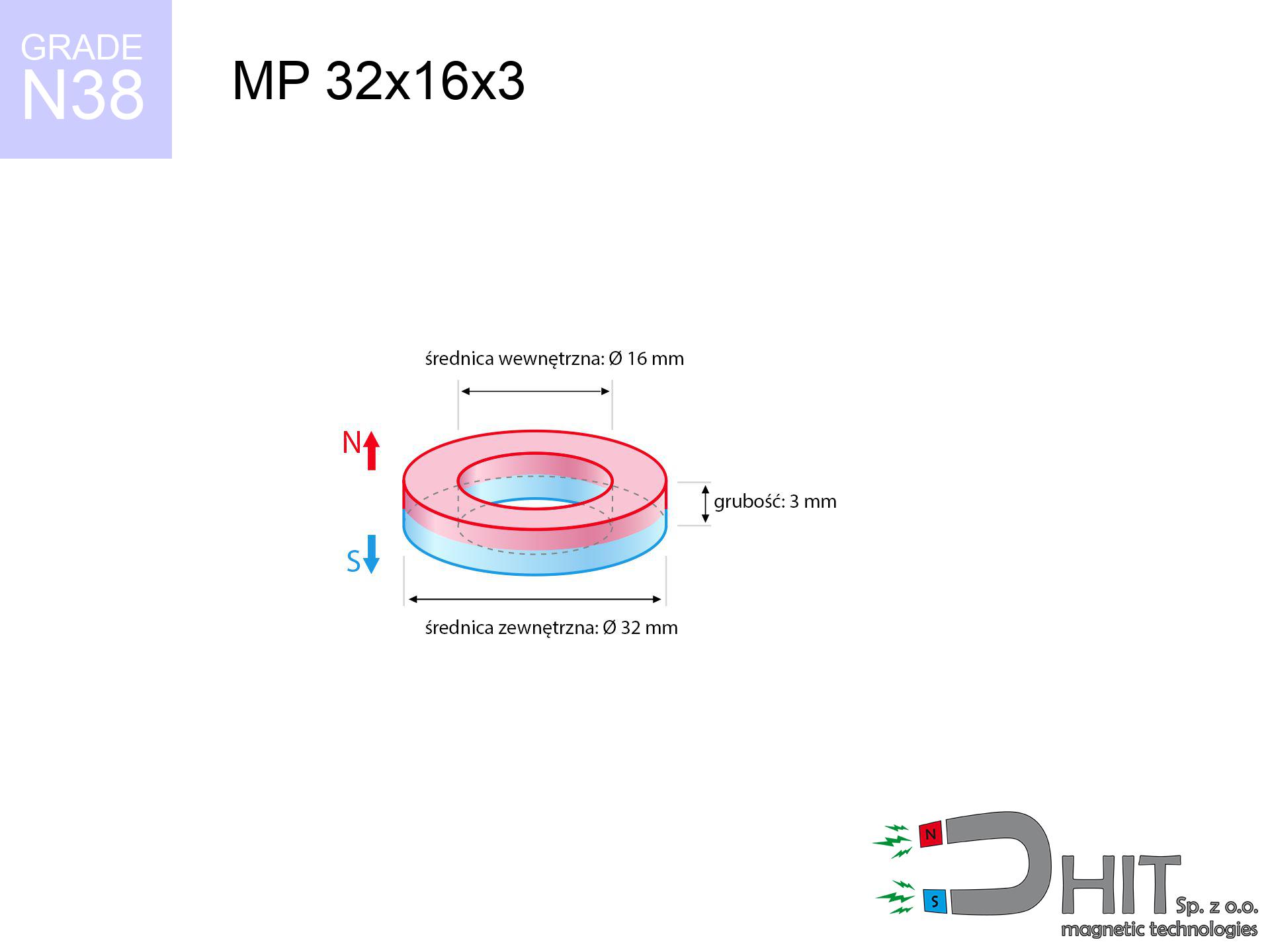
MP 32x16x3 / N38 - ring magnet
ring magnet
Catalog no 030198
GTIN/EAN: 5906301812159
Diameter
32 mm [±0,1 mm]
internal diameter Ø
16 mm [±0,1 mm]
Height
3 mm [±0,1 mm]
Weight
13.57 g
Magnetization Direction
↑ axial
Load capacity
2.79 kg / 27.40 N
Magnetic Induction
114.25 mT / 1142 Gs
Coating
[NiCuNi] Nickel
5.24 ZŁ with VAT / pcs + price for transport
4.26 ZŁ net + 23% VAT / pcs
bulk discounts:
Need more?
Contact us by phone
+48 888 99 98 98
if you prefer let us know by means of
our online form
the contact section.
Lifting power and form of magnets can be verified with our
force calculator.
Same-day shipping for orders placed before 14:00.
Technical - MP 32x16x3 / N38 - ring magnet
Specification / characteristics - MP 32x16x3 / N38 - ring magnet
| properties | values |
|---|---|
| Cat. no. | 030198 |
| GTIN/EAN | 5906301812159 |
| Production/Distribution | Dhit sp. z o.o. |
| Country of origin | Poland / China / Germany |
| Customs code | 85059029 |
| Diameter | 32 mm [±0,1 mm] |
| internal diameter Ø | 16 mm [±0,1 mm] |
| Height | 3 mm [±0,1 mm] |
| Weight | 13.57 g |
| Magnetization Direction | ↑ axial |
| Load capacity ~ ? | 2.79 kg / 27.40 N |
| Magnetic Induction ~ ? | 114.25 mT / 1142 Gs |
| Coating | [NiCuNi] Nickel |
| Manufacturing Tolerance | ±0.1 mm |
Magnetic properties of material N38
| properties | values | units |
|---|---|---|
| remenance Br [min. - max.] ? | 12.2-12.6 | kGs |
| remenance Br [min. - max.] ? | 1220-1260 | mT |
| coercivity bHc ? | 10.8-11.5 | kOe |
| coercivity bHc ? | 860-915 | kA/m |
| actual internal force iHc | ≥ 12 | kOe |
| actual internal force iHc | ≥ 955 | kA/m |
| energy density [min. - max.] ? | 36-38 | BH max MGOe |
| energy density [min. - max.] ? | 287-303 | BH max KJ/m |
| max. temperature ? | ≤ 80 | °C |
Physical properties of sintered neodymium magnets Nd2Fe14B at 20°C
| properties | values | units |
|---|---|---|
| Vickers hardness | ≥550 | Hv |
| Density | ≥7.4 | g/cm3 |
| Curie Temperature TC | 312 - 380 | °C |
| Curie Temperature TF | 593 - 716 | °F |
| Specific resistance | 150 | μΩ⋅cm |
| Bending strength | 250 | MPa |
| Compressive strength | 1000~1100 | MPa |
| Thermal expansion parallel (∥) to orientation (M) | (3-4) x 10-6 | °C-1 |
| Thermal expansion perpendicular (⊥) to orientation (M) | -(1-3) x 10-6 | °C-1 |
| Young's modulus | 1.7 x 10⁴ | kg/mm² |
Engineering simulation of the product - report
Presented information are the outcome of a mathematical calculation. Results were calculated on algorithms for the material Nd2Fe14B. Operational performance might slightly deviate from the simulation results. Use these calculations as a preliminary roadmap during assembly planning.
Table 1: Static pull force (pull vs gap) - characteristics
MP 32x16x3 / N38
| Distance (mm) | Induction (Gauss) / mT | Pull Force (kg/lbs/g/N) | Risk Status |
|---|---|---|---|
| 0 mm |
5552 Gs
555.2 mT
|
2.79 kg / 6.15 pounds
2790.0 g / 27.4 N
|
medium risk |
| 1 mm |
5202 Gs
520.2 mT
|
2.45 kg / 5.40 pounds
2448.8 g / 24.0 N
|
medium risk |
| 2 mm |
4850 Gs
485.0 mT
|
2.13 kg / 4.69 pounds
2128.7 g / 20.9 N
|
medium risk |
| 3 mm |
4504 Gs
450.4 mT
|
1.84 kg / 4.05 pounds
1836.3 g / 18.0 N
|
weak grip |
| 5 mm |
3849 Gs
384.9 mT
|
1.34 kg / 2.96 pounds
1340.5 g / 13.2 N
|
weak grip |
| 10 mm |
2513 Gs
251.3 mT
|
0.57 kg / 1.26 pounds
571.6 g / 5.6 N
|
weak grip |
| 15 mm |
1633 Gs
163.3 mT
|
0.24 kg / 0.53 pounds
241.2 g / 2.4 N
|
weak grip |
| 20 mm |
1087 Gs
108.7 mT
|
0.11 kg / 0.24 pounds
107.0 g / 1.0 N
|
weak grip |
| 30 mm |
535 Gs
53.5 mT
|
0.03 kg / 0.06 pounds
25.9 g / 0.3 N
|
weak grip |
| 50 mm |
181 Gs
18.1 mT
|
0.00 kg / 0.01 pounds
3.0 g / 0.0 N
|
weak grip |
Table 2: Vertical capacity (vertical surface)
MP 32x16x3 / N38
| Distance (mm) | Friction coefficient | Pull Force (kg/lbs/g/N) |
|---|---|---|
| 0 mm | Stal (~0.2) |
0.56 kg / 1.23 pounds
558.0 g / 5.5 N
|
| 1 mm | Stal (~0.2) |
0.49 kg / 1.08 pounds
490.0 g / 4.8 N
|
| 2 mm | Stal (~0.2) |
0.43 kg / 0.94 pounds
426.0 g / 4.2 N
|
| 3 mm | Stal (~0.2) |
0.37 kg / 0.81 pounds
368.0 g / 3.6 N
|
| 5 mm | Stal (~0.2) |
0.27 kg / 0.59 pounds
268.0 g / 2.6 N
|
| 10 mm | Stal (~0.2) |
0.11 kg / 0.25 pounds
114.0 g / 1.1 N
|
| 15 mm | Stal (~0.2) |
0.05 kg / 0.11 pounds
48.0 g / 0.5 N
|
| 20 mm | Stal (~0.2) |
0.02 kg / 0.05 pounds
22.0 g / 0.2 N
|
| 30 mm | Stal (~0.2) |
0.01 kg / 0.01 pounds
6.0 g / 0.1 N
|
| 50 mm | Stal (~0.2) |
0.00 kg / 0.00 pounds
0.0 g / 0.0 N
|
Table 3: Vertical assembly (sliding) - behavior on slippery surfaces
MP 32x16x3 / N38
| Surface type | Friction coefficient / % Mocy | Max load (kg/lbs/g/N) |
|---|---|---|
| Raw steel |
µ = 0.3
30% Nominalnej Siły
|
0.84 kg / 1.85 pounds
837.0 g / 8.2 N
|
| Painted steel (standard) |
µ = 0.2
20% Nominalnej Siły
|
0.56 kg / 1.23 pounds
558.0 g / 5.5 N
|
| Oily/slippery steel |
µ = 0.1
10% Nominalnej Siły
|
0.28 kg / 0.62 pounds
279.0 g / 2.7 N
|
| Magnet with anti-slip rubber |
µ = 0.5
50% Nominalnej Siły
|
1.40 kg / 3.08 pounds
1395.0 g / 13.7 N
|
Table 4: Steel thickness (substrate influence) - sheet metal selection
MP 32x16x3 / N38
| Steel thickness (mm) | % power | Real pull force (kg/lbs/g/N) |
|---|---|---|
| 0.5 mm |
|
0.28 kg / 0.62 pounds
279.0 g / 2.7 N
|
| 1 mm |
|
0.70 kg / 1.54 pounds
697.5 g / 6.8 N
|
| 2 mm |
|
1.40 kg / 3.08 pounds
1395.0 g / 13.7 N
|
| 3 mm |
|
2.09 kg / 4.61 pounds
2092.5 g / 20.5 N
|
| 5 mm |
|
2.79 kg / 6.15 pounds
2790.0 g / 27.4 N
|
| 10 mm |
|
2.79 kg / 6.15 pounds
2790.0 g / 27.4 N
|
| 11 mm |
|
2.79 kg / 6.15 pounds
2790.0 g / 27.4 N
|
| 12 mm |
|
2.79 kg / 6.15 pounds
2790.0 g / 27.4 N
|
Table 5: Thermal resistance (stability) - thermal limit
MP 32x16x3 / N38
| Ambient temp. (°C) | Power loss | Remaining pull (kg/lbs/g/N) | Status |
|---|---|---|---|
| 20 °C | 0.0% |
2.79 kg / 6.15 pounds
2790.0 g / 27.4 N
|
OK |
| 40 °C | -2.2% |
2.73 kg / 6.02 pounds
2728.6 g / 26.8 N
|
OK |
| 60 °C | -4.4% |
2.67 kg / 5.88 pounds
2667.2 g / 26.2 N
|
OK |
| 80 °C | -6.6% |
2.61 kg / 5.74 pounds
2605.9 g / 25.6 N
|
|
| 100 °C | -28.8% |
1.99 kg / 4.38 pounds
1986.5 g / 19.5 N
|
Table 6: Magnet-Magnet interaction (repulsion) - field collision
MP 32x16x3 / N38
| Gap (mm) | Attraction (kg/lbs) (N-S) | Lateral Force (kg/lbs/g/N) | Repulsion (kg/lbs) (N-N) |
|---|---|---|---|
| 0 mm |
128.78 kg / 283.90 pounds
6 014 Gs
|
19.32 kg / 42.59 pounds
19317 g / 189.5 N
|
N/A |
| 1 mm |
120.86 kg / 266.44 pounds
10 757 Gs
|
18.13 kg / 39.97 pounds
18128 g / 177.8 N
|
108.77 kg / 239.80 pounds
~0 Gs
|
| 2 mm |
113.03 kg / 249.19 pounds
10 403 Gs
|
16.95 kg / 37.38 pounds
16954 g / 166.3 N
|
101.73 kg / 224.27 pounds
~0 Gs
|
| 3 mm |
105.49 kg / 232.56 pounds
10 050 Gs
|
15.82 kg / 34.88 pounds
15823 g / 155.2 N
|
94.94 kg / 209.31 pounds
~0 Gs
|
| 5 mm |
91.34 kg / 201.37 pounds
9 352 Gs
|
13.70 kg / 30.21 pounds
13701 g / 134.4 N
|
82.21 kg / 181.23 pounds
~0 Gs
|
| 10 mm |
61.88 kg / 136.41 pounds
7 697 Gs
|
9.28 kg / 20.46 pounds
9281 g / 91.0 N
|
55.69 kg / 122.77 pounds
~0 Gs
|
| 20 mm |
26.38 kg / 58.16 pounds
5 026 Gs
|
3.96 kg / 8.72 pounds
3957 g / 38.8 N
|
23.74 kg / 52.35 pounds
~0 Gs
|
| 50 mm |
2.35 kg / 5.17 pounds
1 499 Gs
|
0.35 kg / 0.78 pounds
352 g / 3.5 N
|
2.11 kg / 4.66 pounds
~0 Gs
|
| 60 mm |
1.19 kg / 2.63 pounds
1 069 Gs
|
0.18 kg / 0.39 pounds
179 g / 1.8 N
|
1.07 kg / 2.37 pounds
~0 Gs
|
| 70 mm |
0.65 kg / 1.42 pounds
786 Gs
|
0.10 kg / 0.21 pounds
97 g / 1.0 N
|
0.58 kg / 1.28 pounds
~0 Gs
|
| 80 mm |
0.37 kg / 0.81 pounds
594 Gs
|
0.06 kg / 0.12 pounds
55 g / 0.5 N
|
0.33 kg / 0.73 pounds
~0 Gs
|
| 90 mm |
0.22 kg / 0.49 pounds
459 Gs
|
0.03 kg / 0.07 pounds
33 g / 0.3 N
|
0.20 kg / 0.44 pounds
~0 Gs
|
| 100 mm |
0.14 kg / 0.30 pounds
362 Gs
|
0.02 kg / 0.05 pounds
21 g / 0.2 N
|
0.12 kg / 0.27 pounds
~0 Gs
|
Table 7: Protective zones (electronics) - warnings
MP 32x16x3 / N38
| Object / Device | Limit (Gauss) / mT | Safe distance |
|---|---|---|
| Pacemaker | 5 Gs (0.5 mT) | 20.5 cm |
| Hearing aid | 10 Gs (1.0 mT) | 16.0 cm |
| Mechanical watch | 20 Gs (2.0 mT) | 12.5 cm |
| Phone / Smartphone | 40 Gs (4.0 mT) | 9.5 cm |
| Remote | 50 Gs (5.0 mT) | 9.0 cm |
| Payment card | 400 Gs (40.0 mT) | 3.5 cm |
| HDD hard drive | 600 Gs (60.0 mT) | 3.0 cm |
Table 8: Dynamics (kinetic energy) - warning
MP 32x16x3 / N38
| Start from (mm) | Speed (km/h) | Energy (J) | Predicted outcome |
|---|---|---|---|
| 10 mm |
16.21 km/h
(4.50 m/s)
|
0.14 J | |
| 30 mm |
25.19 km/h
(7.00 m/s)
|
0.33 J | |
| 50 mm |
32.36 km/h
(8.99 m/s)
|
0.55 J | |
| 100 mm |
45.73 km/h
(12.70 m/s)
|
1.09 J |
Table 9: Corrosion resistance
MP 32x16x3 / N38
| Technical parameter | Value / Description |
|---|---|
| Coating type | [NiCuNi] Nickel |
| Layer structure | Nickel - Copper - Nickel |
| Layer thickness | 10-20 µm |
| Salt spray test (SST) ? | 24 h |
| Recommended environment | Indoors only (dry) |
Table 10: Electrical data (Pc)
MP 32x16x3 / N38
| Parameter | Value | SI Unit / Description |
|---|---|---|
| Magnetic Flux | 38 808 Mx | 388.1 µWb |
| Pc Coefficient | 0.90 | High (Stable) |
Table 11: Physics of underwater searching
MP 32x16x3 / N38
| Environment | Effective steel pull | Effect |
|---|---|---|
| Air (land) | 2.79 kg | Standard |
| Water (riverbed) |
3.19 kg
(+0.40 kg buoyancy gain)
|
+14.5% |
1. Sliding resistance
*Caution: On a vertical wall, the magnet retains just a fraction of its max power.
2. Plate thickness effect
*Thin metal sheet (e.g. computer case) significantly reduces the holding force.
3. Temperature resistance
*For standard magnets, the safety limit is 80°C.
4. Demagnetization curve and operating point (B-H)
chart generated for the permeance coefficient Pc (Permeance Coefficient) = 0.90
This simulation demonstrates the magnetic stability of the selected magnet under specific geometric conditions. The solid red line represents the demagnetization curve (material potential), while the dashed blue line is the load line based on the magnet's geometry. The Pc (Permeance Coefficient), also known as the load line slope, is a dimensionless value that describes the relationship between the magnet's shape and its magnetic stability. The intersection of these two lines (the black dot) is the operating point — it determines the actual magnetic flux density generated by the magnet in this specific configuration. A higher Pc value means the magnet is more 'slender' (tall relative to its area), resulting in a higher operating point and better resistance to irreversible demagnetization caused by external fields or temperature. A value of 0.42 is relatively low (typical for flat magnets), meaning the operating point is closer to the 'knee' of the curve — caution is advised when operating at temperatures near the maximum limit to avoid strength loss.
Elemental analysis
| iron (Fe) | 64% – 68% |
| neodymium (Nd) | 29% – 32% |
| boron (B) | 1.1% – 1.2% |
| dysprosium (Dy) | 0.5% – 2.0% |
| coating (Ni-Cu-Ni) | < 0.05% |
Ecology and recycling (GPSR)
| recyclability (EoL) | 100% |
| recycled raw materials | ~10% (pre-cons) |
| carbon footprint | low / zredukowany |
| waste code (EWC) | 16 02 16 |
Other proposals
![HH 42x8.8 [M6] / N38 - through hole magnetic holder](https://cdn3.dhit.pl/graphics/products/hh-42x8.8-m6-hin.jpg "HH 42x8.8 [M6] / N38 - through hole magnetic holder")


Advantages and disadvantages of rare earth magnets.
Strengths
- Their power is maintained, and after around 10 years it decreases only by ~1% (theoretically),
- Neodymium magnets remain remarkably resistant to magnetic field loss caused by external interference,
- By using a smooth layer of gold, the element has an professional look,
- The surface of neodymium magnets generates a powerful magnetic field – this is one of their assets,
- Thanks to resistance to high temperature, they are able to function (depending on the shape) even at temperatures up to 230°C and higher...
- Considering the ability of precise forming and adaptation to unique requirements, neodymium magnets can be created in a broad palette of geometric configurations, which increases their versatility,
- Huge importance in modern industrial fields – they serve a role in mass storage devices, electromotive mechanisms, medical devices, also modern systems.
- Thanks to efficiency per cm³, small magnets offer high operating force, occupying minimum space,
Disadvantages
- They are prone to damage upon heavy impacts. To avoid cracks, it is worth securing magnets using a steel holder. Such protection not only shields the magnet but also improves its resistance to damage
- We warn that neodymium magnets can lose their strength at high temperatures. To prevent this, we recommend our specialized [AH] magnets, which work effectively even at 230°C.
- Magnets exposed to a humid environment can rust. Therefore when using outdoors, we advise using waterproof magnets made of rubber, plastic or other material resistant to moisture
- Due to limitations in realizing threads and complex shapes in magnets, we propose using casing - magnetic holder.
- Possible danger to health – tiny shards of magnets pose a threat, when accidentally swallowed, which becomes key in the aspect of protecting the youngest. Furthermore, small components of these devices can be problematic in diagnostics medical when they are in the body.
- With budget limitations the cost of neodymium magnets is a challenge,
Pull force analysis
Breakaway strength of the magnet in ideal conditions – what it depends on?
- on a base made of mild steel, effectively closing the magnetic field
- with a cross-section minimum 10 mm
- characterized by lack of roughness
- under conditions of gap-free contact (metal-to-metal)
- during detachment in a direction perpendicular to the mounting surface
- in temp. approx. 20°C
Impact of factors on magnetic holding capacity in practice
- Air gap (betwixt the magnet and the metal), as even a tiny distance (e.g. 0.5 mm) leads to a reduction in force by up to 50% (this also applies to paint, corrosion or dirt).
- Direction of force – maximum parameter is obtained only during perpendicular pulling. The shear force of the magnet along the plate is usually many times lower (approx. 1/5 of the lifting capacity).
- Metal thickness – the thinner the sheet, the weaker the hold. Magnetic flux passes through the material instead of converting into lifting capacity.
- Steel type – mild steel attracts best. Higher carbon content lower magnetic properties and lifting capacity.
- Plate texture – ground elements guarantee perfect abutment, which improves field saturation. Uneven metal reduce efficiency.
- Thermal factor – hot environment reduces magnetic field. Exceeding the limit temperature can permanently damage the magnet.
Lifting capacity testing was performed on plates with a smooth surface of optimal thickness, under a perpendicular pulling force, however under parallel forces the load capacity is reduced by as much as fivefold. Additionally, even a slight gap between the magnet and the plate reduces the holding force.
Safety rules for work with neodymium magnets
Nickel allergy
Studies show that the nickel plating (standard magnet coating) is a common allergen. If your skin reacts to metals, prevent direct skin contact or select coated magnets.
Thermal limits
Monitor thermal conditions. Heating the magnet above 80 degrees Celsius will permanently weaken its properties and strength.
Bodily injuries
Danger of trauma: The pulling power is so immense that it can result in hematomas, pinching, and even bone fractures. Use thick gloves.
Magnet fragility
Watch out for shards. Magnets can explode upon uncontrolled impact, launching shards into the air. Eye protection is mandatory.
Life threat
Life threat: Strong magnets can turn off pacemakers and defibrillators. Do not approach if you have medical devices.
Safe operation
Before use, read the rules. Uncontrolled attraction can destroy the magnet or hurt your hand. Think ahead.
No play value
Absolutely keep magnets away from children. Risk of swallowing is high, and the effects of magnets connecting inside the body are life-threatening.
GPS and phone interference
Navigation devices and mobile phones are extremely susceptible to magnetic fields. Close proximity with a strong magnet can ruin the internal compass in your phone.
Electronic devices
Data protection: Neodymium magnets can damage payment cards and sensitive devices (pacemakers, hearing aids, mechanical watches).
Dust explosion hazard
Machining of neodymium magnets carries a risk of fire risk. Magnetic powder oxidizes rapidly with oxygen and is hard to extinguish.
Tabela kosztu i czasu dostawy
Płatność przed wysyłką:

GLS kurier
Przesyłka będzie u Ciebie za 2-3 dni
14.99 ZŁ

InPost Paczkomaty 24/7
Przesyłka będzie u Ciebie za 1-2 dni
12.30 ZŁ
Płatność przy odbiorze (pobranie):
GLS kurier
Przesyłka będzie u Ciebie za 1-2 dni
23.00 ZŁ
Rate the product
Your rating