

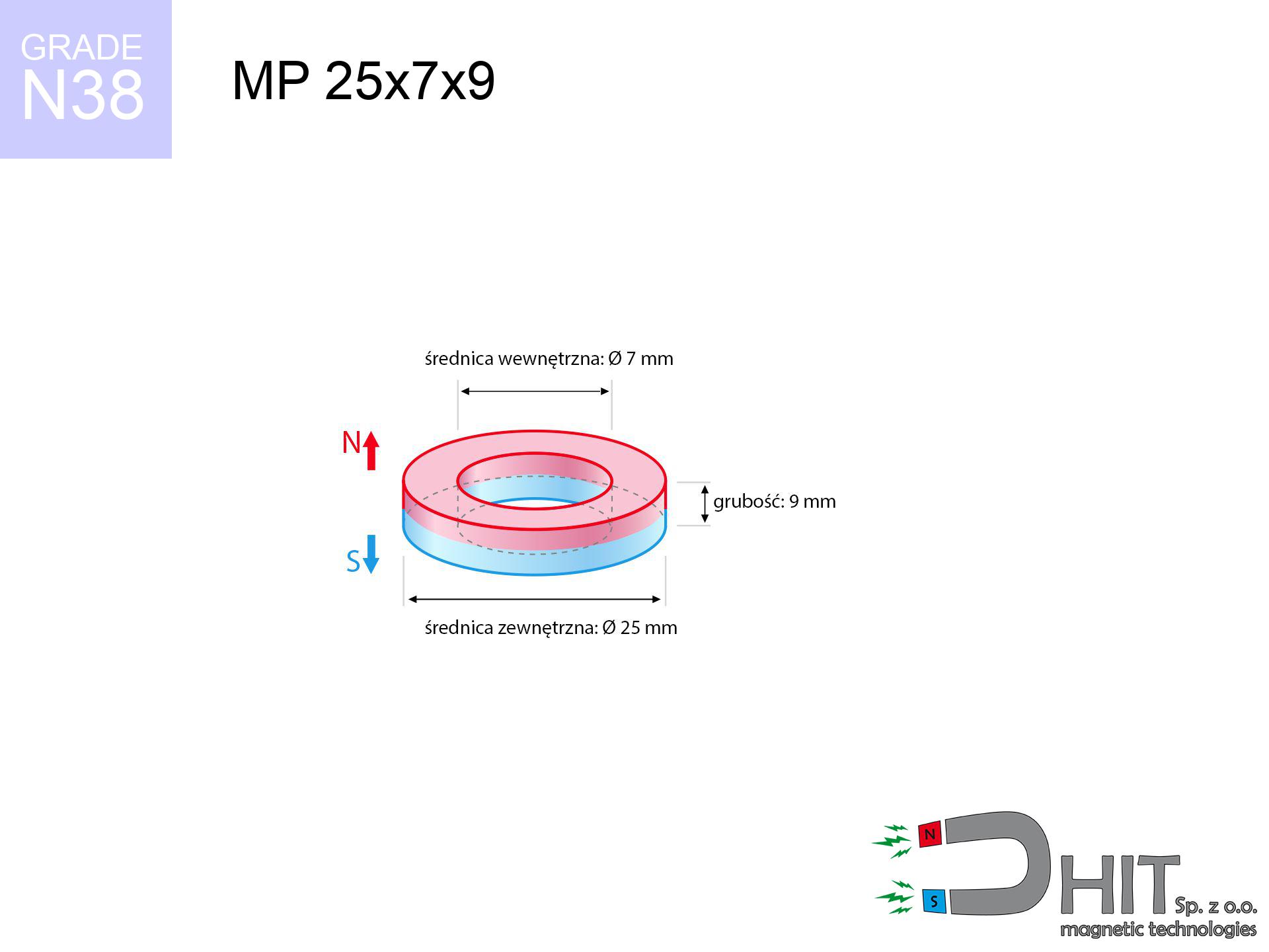
MP 25x7x9 / N38 - ring magnet
ring magnet
Catalog no 030195
GTIN/EAN: 5906301812128
- Diameter
- 25 mm [±0,1 mm]
- internal diameter Ø
- 7 mm [±0,1 mm]
- Height
- 9 mm [±0,1 mm]
- Weight
- 30.54 g
- Magnetization Direction
- ↑ axial
- Coating
- [NiCuNi] Nickel
12.55 zł with VAT / pcs + price for transport
10.20 zł net + 23% VAT / pcs
bulk discounts:
Need more?Engineering report for this magnet
Full PDF analysis: pull and shear force, effect of distance, temperature and plate thickness, safety distances and the demagnetization curve.
Call us
+48 888 99 98 98
otherwise let us know via
form
the contact section.
Strength along with structure of neodymium magnets can be analyzed on our
magnetic mass calculator.
Same-day processing for orders placed before 14:00.
Product card - MP 25x7x9 / N38 - ring magnet
Specification / characteristics - MP 25x7x9 / N38 - ring magnet
| properties | values |
|---|---|
| Cat. no. | 030195 |
| GTIN/EAN | 5906301812128 |
| Production/Distribution | Dhit sp. z o.o. |
| Country of origin | Poland / China / Germany |
| Customs code | 85059029 |
| Diameter | 25 mm [±0,1 mm] |
| internal diameter Ø | 7 mm [±0,1 mm] |
| Height | 9 mm [±0,1 mm] |
| Weight | 30.54 g |
| Magnetization Direction | ↑ axial |
| Load capacity ~ ? | 14.82 kg / 145.39 N |
| Magnetic Induction ~ ? | 362.13 mT / 3621 Gs |
| Coating | [NiCuNi] Nickel |
| Manufacturing Tolerance | ±0.1 mm |
Magnetic properties of material N38
| properties | values | units |
|---|---|---|
| remenance Br [min. - max.] ? | 12.2-12.6 | kGs |
| remenance Br [min. - max.] ? | 1220-1260 | mT |
| coercivity bHc ? | 10.8-11.5 | kOe |
| coercivity bHc ? | 860-915 | kA/m |
| actual internal force iHc | ≥ 12 | kOe |
| actual internal force iHc | ≥ 955 | kA/m |
| energy density [min. - max.] ? | 36-38 | BH max MGOe |
| energy density [min. - max.] ? | 287-303 | BH max KJ/m |
| max. temperature ? | ≤ 80 | °C |
Physical properties of sintered neodymium magnets Nd2Fe14B at 20°C
| properties | values | units |
|---|---|---|
| Vickers hardness | ≥550 | Hv |
| Density | ≥7.4 | g/cm3 |
| Curie Temperature TC | 312 - 380 | °C |
| Curie Temperature TF | 593 - 716 | °F |
| Specific resistance | 150 | μΩ⋅cm |
| Bending strength | 250 | MPa |
| Compressive strength | 1000~1100 | MPa |
| Thermal expansion parallel (∥) to orientation (M) | (3-4) x 10-6 | °C-1 |
| Thermal expansion perpendicular (⊥) to orientation (M) | -(1-3) x 10-6 | °C-1 |
| Young's modulus | 1.7 x 10⁴ | kg/mm² |
Physical analysis of the product - technical parameters
The following information represent the direct effect of a physical simulation. Results are based on algorithms for the class Nd2Fe14B. Operational parameters might slightly differ. Treat these calculations as a preliminary roadmap during assembly planning.
Table 1: Static pull force (pull vs gap) - interaction chart
MP 25x7x9 / N38
| Distance (mm) | Induction (Gauss) / mT | Pull Force (kg/lbs/g/N) | Risk Status |
|---|---|---|---|
| 0 mm |
5777 Gs
577.7 mT
|
14.82 kg / 32.67 lbs
14820.0 g / 145.4 N
|
crushing |
| 1 mm |
5310 Gs
531.0 mT
|
12.52 kg / 27.60 lbs
12519.6 g / 122.8 N
|
crushing |
| 2 mm |
4846 Gs
484.6 mT
|
10.43 kg / 22.98 lbs
10425.5 g / 102.3 N
|
crushing |
| 3 mm |
4397 Gs
439.7 mT
|
8.59 kg / 18.93 lbs
8586.1 g / 84.2 N
|
medium risk |
| 5 mm |
3576 Gs
357.6 mT
|
5.68 kg / 12.52 lbs
5678.0 g / 55.7 N
|
medium risk |
| 10 mm |
2073 Gs
207.3 mT
|
1.91 kg / 4.21 lbs
1907.5 g / 18.7 N
|
low risk |
| 15 mm |
1231 Gs
123.1 mT
|
0.67 kg / 1.48 lbs
673.1 g / 6.6 N
|
low risk |
| 20 mm |
773 Gs
77.3 mT
|
0.27 kg / 0.58 lbs
265.0 g / 2.6 N
|
low risk |
| 30 mm |
356 Gs
35.6 mT
|
0.06 kg / 0.12 lbs
56.2 g / 0.6 N
|
low risk |
| 50 mm |
115 Gs
11.5 mT
|
0.01 kg / 0.01 lbs
5.9 g / 0.1 N
|
low risk |
Table 2: Shear capacity (vertical surface)
MP 25x7x9 / N38
| Distance (mm) | Friction coefficient | Pull Force (kg/lbs/g/N) |
|---|---|---|
| 0 mm | Stal (~0.2) |
2.96 kg / 6.53 lbs
2964.0 g / 29.1 N
|
| 1 mm | Stal (~0.2) |
2.50 kg / 5.52 lbs
2504.0 g / 24.6 N
|
| 2 mm | Stal (~0.2) |
2.09 kg / 4.60 lbs
2086.0 g / 20.5 N
|
| 3 mm | Stal (~0.2) |
1.72 kg / 3.79 lbs
1718.0 g / 16.9 N
|
| 5 mm | Stal (~0.2) |
1.14 kg / 2.50 lbs
1136.0 g / 11.1 N
|
| 10 mm | Stal (~0.2) |
0.38 kg / 0.84 lbs
382.0 g / 3.7 N
|
| 15 mm | Stal (~0.2) |
0.13 kg / 0.30 lbs
134.0 g / 1.3 N
|
| 20 mm | Stal (~0.2) |
0.05 kg / 0.12 lbs
54.0 g / 0.5 N
|
| 30 mm | Stal (~0.2) |
0.01 kg / 0.03 lbs
12.0 g / 0.1 N
|
| 50 mm | Stal (~0.2) |
0.00 kg / 0.00 lbs
2.0 g / 0.0 N
|
Table 3: Vertical assembly (shearing) - vertical pull
MP 25x7x9 / N38
| Surface type | Friction coefficient / % Mocy | Max load (kg/lbs/g/N) |
|---|---|---|
| Raw steel |
µ = 0.3
30% Nominalnej Siły
|
4.45 kg / 9.80 lbs
4446.0 g / 43.6 N
|
| Painted steel (standard) |
µ = 0.2
20% Nominalnej Siły
|
2.96 kg / 6.53 lbs
2964.0 g / 29.1 N
|
| Oily/slippery steel |
µ = 0.1
10% Nominalnej Siły
|
1.48 kg / 3.27 lbs
1482.0 g / 14.5 N
|
| Magnet with anti-slip rubber |
µ = 0.5
50% Nominalnej Siły
|
7.41 kg / 16.34 lbs
7410.0 g / 72.7 N
|
Table 4: Material efficiency (substrate influence) - power losses
MP 25x7x9 / N38
| Steel thickness (mm) | % power | Real pull force (kg/lbs/g/N) |
|---|---|---|
| 0.5 mm |
|
0.74 kg / 1.63 lbs
741.0 g / 7.3 N
|
| 1 mm |
|
1.85 kg / 4.08 lbs
1852.5 g / 18.2 N
|
| 2 mm |
|
3.71 kg / 8.17 lbs
3705.0 g / 36.3 N
|
| 3 mm |
|
5.56 kg / 12.25 lbs
5557.5 g / 54.5 N
|
| 5 mm |
|
9.26 kg / 20.42 lbs
9262.5 g / 90.9 N
|
| 10 mm |
|
14.82 kg / 32.67 lbs
14820.0 g / 145.4 N
|
| 11 mm |
|
14.82 kg / 32.67 lbs
14820.0 g / 145.4 N
|
| 12 mm |
|
14.82 kg / 32.67 lbs
14820.0 g / 145.4 N
|
Table 5: Thermal stability (material behavior) - power drop
MP 25x7x9 / N38
| Ambient temp. (°C) | Power loss | Remaining pull (kg/lbs/g/N) | Status |
|---|---|---|---|
| 20 °C | 0.0% |
14.82 kg / 32.67 lbs
14820.0 g / 145.4 N
|
OK |
| 40 °C | -2.2% |
14.49 kg / 31.95 lbs
14494.0 g / 142.2 N
|
OK |
| 60 °C | -4.4% |
14.17 kg / 31.23 lbs
14167.9 g / 139.0 N
|
OK |
| 80 °C | -6.6% |
13.84 kg / 30.52 lbs
13841.9 g / 135.8 N
|
|
| 100 °C | -28.8% |
10.55 kg / 23.26 lbs
10551.8 g / 103.5 N
|
Table 6: Magnet-Magnet interaction (attraction) - field range
MP 25x7x9 / N38
| Gap (mm) | Attraction (kg/lbs) (N-S) | Lateral Force (kg/lbs/g/N) | Repulsion (kg/lbs) (N-N) |
|---|---|---|---|
| 0 mm |
74.73 kg / 164.76 lbs
6 082 Gs
|
11.21 kg / 24.71 lbs
11210 g / 110.0 N
|
N/A |
| 1 mm |
68.86 kg / 151.81 lbs
11 091 Gs
|
10.33 kg / 22.77 lbs
10329 g / 101.3 N
|
61.97 kg / 136.63 lbs
~0 Gs
|
| 2 mm |
63.13 kg / 139.18 lbs
10 620 Gs
|
9.47 kg / 20.88 lbs
9470 g / 92.9 N
|
56.82 kg / 125.26 lbs
~0 Gs
|
| 3 mm |
57.70 kg / 127.20 lbs
10 153 Gs
|
8.65 kg / 19.08 lbs
8654 g / 84.9 N
|
51.93 kg / 114.48 lbs
~0 Gs
|
| 5 mm |
47.77 kg / 105.31 lbs
9 238 Gs
|
7.17 kg / 15.80 lbs
7165 g / 70.3 N
|
42.99 kg / 94.78 lbs
~0 Gs
|
| 10 mm |
28.63 kg / 63.12 lbs
7 152 Gs
|
4.29 kg / 9.47 lbs
4295 g / 42.1 N
|
25.77 kg / 56.81 lbs
~0 Gs
|
| 20 mm |
9.62 kg / 21.21 lbs
4 145 Gs
|
1.44 kg / 3.18 lbs
1443 g / 14.2 N
|
8.66 kg / 19.09 lbs
~0 Gs
|
| 50 mm |
0.59 kg / 1.29 lbs
1 024 Gs
|
0.09 kg / 0.19 lbs
88 g / 0.9 N
|
0.53 kg / 1.16 lbs
~0 Gs
|
| 60 mm |
0.28 kg / 0.62 lbs
712 Gs
|
0.04 kg / 0.09 lbs
43 g / 0.4 N
|
0.26 kg / 0.56 lbs
~0 Gs
|
| 70 mm |
0.15 kg / 0.33 lbs
514 Gs
|
0.02 kg / 0.05 lbs
22 g / 0.2 N
|
0.13 kg / 0.29 lbs
~0 Gs
|
| 80 mm |
0.08 kg / 0.18 lbs
383 Gs
|
0.01 kg / 0.03 lbs
12 g / 0.1 N
|
0.07 kg / 0.16 lbs
~0 Gs
|
| 90 mm |
0.05 kg / 0.11 lbs
293 Gs
|
0.01 kg / 0.02 lbs
7 g / 0.1 N
|
0.04 kg / 0.10 lbs
~0 Gs
|
| 100 mm |
0.03 kg / 0.07 lbs
230 Gs
|
0.00 kg / 0.01 lbs
4 g / 0.0 N
|
0.03 kg / 0.06 lbs
~0 Gs
|
Table 7: Safety (HSE) (electronics) - precautionary measures
MP 25x7x9 / N38
| Object / Device | Limit (Gauss) / mT | Safe distance |
|---|---|---|
| Pacemaker | 5 Gs (0.5 mT) | 17.0 cm |
| Hearing aid | 10 Gs (1.0 mT) | 13.5 cm |
| Mechanical watch | 20 Gs (2.0 mT) | 10.5 cm |
| Phone / Smartphone | 40 Gs (4.0 mT) | 8.0 cm |
| Remote | 50 Gs (5.0 mT) | 7.5 cm |
| Payment card | 400 Gs (40.0 mT) | 3.0 cm |
| HDD hard drive | 600 Gs (60.0 mT) | 2.5 cm |
Table 8: Collisions (cracking risk) - collision effects
MP 25x7x9 / N38
| Start from (mm) | Speed (km/h) | Energy (J) | Predicted outcome |
|---|---|---|---|
| 10 mm |
23.44 km/h
(6.51 m/s)
|
0.65 J | |
| 30 mm |
25.05 km/h
(6.96 m/s)
|
0.74 J | |
| 50 mm |
25.12 km/h
(6.98 m/s)
|
0.74 J | |
| 100 mm |
25.13 km/h
(6.98 m/s)
|
0.74 J |
Table 9: Anti-corrosion coating durability
MP 25x7x9 / N38
| Technical parameter | Value / Description |
|---|---|
| Coating type | [NiCuNi] Nickel |
| Layer structure | Nickel - Copper - Nickel |
| Layer thickness | 10-20 µm |
| Salt spray test (SST) ? | 24 h |
| Recommended environment | Indoors only (dry) |
Table 10: Electrical data (Flux)
MP 25x7x9 / N38
| Parameter | Value | SI Unit / Description |
|---|---|---|
| Magnetic Flux | 22 495 Mx | 225.0 µWb |
| Pc Coefficient | 1.05 | High (Stable) |
Table 11: Submerged application
MP 25x7x9 / N38
| Environment | Effective steel pull | Effect |
|---|---|---|
| Air (land) | 14.82 kg | Standard |
| Water (riverbed) |
16.97 kg
(+2.15 kg buoyancy gain)
|
+14.5% |
1. Shear force
*Warning: On a vertical wall, the magnet retains merely ~20% of its nominal pull.
2. Steel saturation
*Thin metal sheet (e.g. 0.5mm PC case) severely weakens the holding force.
3. Temperature resistance
*For N38 material, the safety limit is 80°C.
4. Demagnetization curve and operating point (B-H)
chart generated for the permeance coefficient Pc (Permeance Coefficient) = 1.05
The chart above illustrates the magnetic characteristics of the material within the second quadrant of the hysteresis loop. The solid red line represents the demagnetization curve (material potential), while the dashed blue line is the load line based on the magnet's geometry. The Pc (Permeance Coefficient), also known as the load line slope, is a dimensionless value that describes the relationship between the magnet's shape and its magnetic stability. The intersection of these two lines (the black dot) is the operating point — it determines the actual magnetic flux density generated by the magnet in this specific configuration. A higher Pc value means the magnet is more 'slender' (tall relative to its area), resulting in a higher operating point and better resistance to irreversible demagnetization caused by external fields or temperature. A value of 0.42 is relatively low (typical for flat magnets), meaning the operating point is closer to the 'knee' of the curve — caution is advised when operating at temperatures near the maximum limit to avoid strength loss.
Elemental analysis
| iron (Fe) | 64% – 68% |
| neodymium (Nd) | 29% – 32% |
| boron (B) | 1.1% – 1.2% |
| dysprosium (Dy) | 0.5% – 2.0% |
| coating (Ni-Cu-Ni) | < 0.05% |
Environmental data
| recyclability (EoL) | 100% |
| recycled raw materials | ~10% (pre-cons) |
| carbon footprint | low / zredukowany |
| waste code (EWC) | 16 02 16 |
Other proposals

![UMGW 32x18x8 [M6] GW / N38 - magnetic holder internal thread](https://cdn3.dhit.pl/graphics/products/um32x18x8-m6-gw--hec.jpg "UMGW 32x18x8 [M6] GW / N38 - magnetic holder internal thread")


Pros and cons of Nd2Fe14B magnets.
Strengths
- They retain full power for nearly ten years – the loss is just ~1% (according to analyses),
- Magnets effectively defend themselves against loss of magnetization caused by external fields,
- In other words, due to the glossy layer of gold, the element gains a professional look,
- Neodymium magnets achieve maximum magnetic induction on a their surface, which increases force concentration,
- Through (adequate) combination of ingredients, they can achieve high thermal strength, allowing for functioning at temperatures approaching 230°C and above...
- Thanks to flexibility in constructing and the ability to adapt to individual projects,
- Universal use in innovative solutions – they are utilized in magnetic memories, electromotive mechanisms, medical equipment, also complex engineering applications.
- Compactness – despite small sizes they provide effective action, making them ideal for precision applications
Weaknesses
- They are fragile upon too strong impacts. To avoid cracks, it is worth securing magnets in special housings. Such protection not only shields the magnet but also improves its resistance to damage
- When exposed to high temperature, neodymium magnets experience a drop in power. Often, when the temperature exceeds 80°C, their strength decreases (depending on the size and shape of the magnet). For those who need magnets for extreme conditions, we offer [AH] versions withstanding up to 230°C
- They rust in a humid environment - during use outdoors we advise using waterproof magnets e.g. in rubber, plastic
- Due to limitations in creating nuts and complex forms in magnets, we recommend using cover - magnetic mechanism.
- Health risk resulting from small fragments of magnets are risky, when accidentally swallowed, which gains importance in the context of child health protection. Furthermore, small components of these products can be problematic in diagnostics medical when they are in the body.
- High unit price – neodymium magnets cost more than other types of magnets (e.g. ferrite), which increases costs of application in large quantities
Lifting parameters
Optimal lifting capacity of a neodymium magnet – what contributes to it?
- with the contact of a sheet made of low-carbon steel, ensuring full magnetic saturation
- whose thickness reaches at least 10 mm
- with an ground contact surface
- without the slightest insulating layer between the magnet and steel
- during detachment in a direction vertical to the plane
- in neutral thermal conditions
What influences lifting capacity in practice
- Gap (betwixt the magnet and the plate), as even a very small distance (e.g. 0.5 mm) results in a reduction in force by up to 50% (this also applies to varnish, corrosion or dirt).
- Angle of force application – maximum parameter is obtained only during pulling at a 90° angle. The shear force of the magnet along the plate is standardly several times smaller (approx. 1/5 of the lifting capacity).
- Base massiveness – insufficiently thick steel does not close the flux, causing part of the flux to be wasted to the other side.
- Chemical composition of the base – mild steel attracts best. Higher carbon content reduce magnetic properties and holding force.
- Base smoothness – the smoother and more polished the surface, the larger the contact zone and higher the lifting capacity. Unevenness creates an air distance.
- Temperature influence – high temperature weakens magnetic field. Too high temperature can permanently demagnetize the magnet.
Lifting capacity was measured using a steel plate with a smooth surface of suitable thickness (min. 20 mm), under perpendicular detachment force, in contrast under shearing force the holding force is lower. In addition, even a slight gap between the magnet and the plate reduces the holding force.
Precautions when working with NdFeB magnets
Fire warning
Fire hazard: Neodymium dust is highly flammable. Avoid machining magnets without safety gear as this risks ignition.
Thermal limits
Avoid heat. Neodymium magnets are sensitive to temperature. If you require operation above 80°C, ask us about special high-temperature series (H, SH, UH).
Metal Allergy
Some people suffer from a contact allergy to nickel, which is the common plating for NdFeB magnets. Prolonged contact might lead to a rash. We suggest wear safety gloves.
Threat to electronics
Very strong magnetic fields can destroy records on payment cards, hard drives, and storage devices. Keep a distance of min. 10 cm.
Phone sensors
Remember: rare earth magnets generate a field that disrupts sensitive sensors. Maintain a safe distance from your phone, device, and GPS.
Safe operation
Handle magnets consciously. Their huge power can surprise even professionals. Be vigilant and respect their power.
Fragile material
Protect your eyes. Magnets can fracture upon uncontrolled impact, launching sharp fragments into the air. Eye protection is mandatory.
Pinching danger
Big blocks can crush fingers in a fraction of a second. Under no circumstances put your hand between two strong magnets.
Adults only
Product intended for adults. Small elements can be swallowed, leading to serious injuries. Store away from children and animals.
Pacemakers
For implant holders: Powerful magnets affect electronics. Maintain minimum 30 cm distance or ask another person to work with the magnets.
Tabela kosztu i czasu dostawy
Płatność przed wysyłką:

GLS kurier
Przesyłka będzie u Ciebie za 2-3 dni
14.99 ZŁ

InPost Paczkomaty 24/7
Przesyłka będzie u Ciebie za 1-2 dni
12.30 ZŁ
Płatność przy odbiorze (pobranie):
GLS kurier
Przesyłka będzie u Ciebie za 1-2 dni
23.00 ZŁ
Rate the product
Your rating