
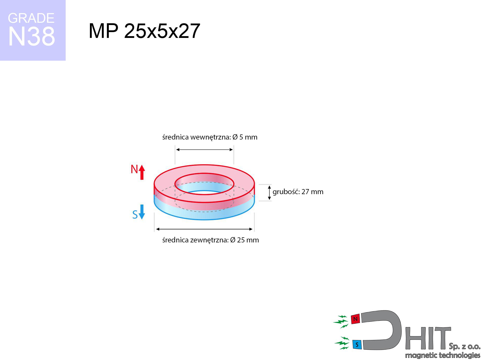
MP 25x5x27 / N38 - ring magnet
ring magnet
Catalog no 030192
GTIN/EAN: 5906301812098
Diameter
25 mm [±0,1 mm]
internal diameter Ø
5 mm [±0,1 mm]
Height
27 mm [±0,1 mm]
Weight
95.43 g
Magnetization Direction
↑ axial
Load capacity
18.51 kg / 181.54 N
Magnetic Induction
562.34 mT / 5623 Gs
Coating
[NiCuNi] Nickel
47.18 ZŁ with VAT / pcs + price for transport
38.36 ZŁ net + 23% VAT / pcs
bulk discounts:
Need more?
Call us
+48 22 499 98 98
if you prefer drop us a message through
inquiry form
our website.
Weight along with form of magnets can be estimated with our
power calculator.
Order by 14:00 and we’ll ship today!
Technical - MP 25x5x27 / N38 - ring magnet
Specification / characteristics - MP 25x5x27 / N38 - ring magnet
| properties | values |
|---|---|
| Cat. no. | 030192 |
| GTIN/EAN | 5906301812098 |
| Production/Distribution | Dhit sp. z o.o. |
| Country of origin | Poland / China / Germany |
| Customs code | 85059029 |
| Diameter | 25 mm [±0,1 mm] |
| internal diameter Ø | 5 mm [±0,1 mm] |
| Height | 27 mm [±0,1 mm] |
| Weight | 95.43 g |
| Magnetization Direction | ↑ axial |
| Load capacity ~ ? | 18.51 kg / 181.54 N |
| Magnetic Induction ~ ? | 562.34 mT / 5623 Gs |
| Coating | [NiCuNi] Nickel |
| Manufacturing Tolerance | ±0.1 mm |
Magnetic properties of material N38
| properties | values | units |
|---|---|---|
| remenance Br [min. - max.] ? | 12.2-12.6 | kGs |
| remenance Br [min. - max.] ? | 1220-1260 | mT |
| coercivity bHc ? | 10.8-11.5 | kOe |
| coercivity bHc ? | 860-915 | kA/m |
| actual internal force iHc | ≥ 12 | kOe |
| actual internal force iHc | ≥ 955 | kA/m |
| energy density [min. - max.] ? | 36-38 | BH max MGOe |
| energy density [min. - max.] ? | 287-303 | BH max KJ/m |
| max. temperature ? | ≤ 80 | °C |
Physical properties of sintered neodymium magnets Nd2Fe14B at 20°C
| properties | values | units |
|---|---|---|
| Vickers hardness | ≥550 | Hv |
| Density | ≥7.4 | g/cm3 |
| Curie Temperature TC | 312 - 380 | °C |
| Curie Temperature TF | 593 - 716 | °F |
| Specific resistance | 150 | μΩ⋅cm |
| Bending strength | 250 | MPa |
| Compressive strength | 1000~1100 | MPa |
| Thermal expansion parallel (∥) to orientation (M) | (3-4) x 10-6 | °C-1 |
| Thermal expansion perpendicular (⊥) to orientation (M) | -(1-3) x 10-6 | °C-1 |
| Young's modulus | 1.7 x 10⁴ | kg/mm² |
Physical analysis of the assembly - report
The following values represent the outcome of a engineering simulation. Results rely on algorithms for the material Nd2Fe14B. Operational conditions might slightly differ from theoretical values. Use these calculations as a reference point during assembly planning.
Table 1: Static force (force vs gap) - power drop
MP 25x5x27 / N38
| Distance (mm) | Induction (Gauss) / mT | Pull Force (kg/lbs/g/N) | Risk Status |
|---|---|---|---|
| 0 mm |
5716 Gs
571.6 mT
|
18.51 kg / 40.81 lbs
18510.0 g / 181.6 N
|
crushing |
| 1 mm |
5288 Gs
528.8 mT
|
15.84 kg / 34.92 lbs
15839.8 g / 155.4 N
|
crushing |
| 2 mm |
4861 Gs
486.1 mT
|
13.38 kg / 29.51 lbs
13384.0 g / 131.3 N
|
crushing |
| 3 mm |
4446 Gs
444.6 mT
|
11.20 kg / 24.69 lbs
11198.0 g / 109.9 N
|
crushing |
| 5 mm |
3677 Gs
367.7 mT
|
7.66 kg / 16.88 lbs
7657.5 g / 75.1 N
|
medium risk |
| 10 mm |
2216 Gs
221.6 mT
|
2.78 kg / 6.13 lbs
2782.1 g / 27.3 N
|
medium risk |
| 15 mm |
1354 Gs
135.4 mT
|
1.04 kg / 2.29 lbs
1037.8 g / 10.2 N
|
safe |
| 20 mm |
864 Gs
86.4 mT
|
0.42 kg / 0.93 lbs
423.3 g / 4.2 N
|
safe |
| 30 mm |
405 Gs
40.5 mT
|
0.09 kg / 0.21 lbs
93.1 g / 0.9 N
|
safe |
| 50 mm |
133 Gs
13.3 mT
|
0.01 kg / 0.02 lbs
10.0 g / 0.1 N
|
safe |
Table 2: Shear force (wall)
MP 25x5x27 / N38
| Distance (mm) | Friction coefficient | Pull Force (kg/lbs/g/N) |
|---|---|---|
| 0 mm | Stal (~0.2) |
3.70 kg / 8.16 lbs
3702.0 g / 36.3 N
|
| 1 mm | Stal (~0.2) |
3.17 kg / 6.98 lbs
3168.0 g / 31.1 N
|
| 2 mm | Stal (~0.2) |
2.68 kg / 5.90 lbs
2676.0 g / 26.3 N
|
| 3 mm | Stal (~0.2) |
2.24 kg / 4.94 lbs
2240.0 g / 22.0 N
|
| 5 mm | Stal (~0.2) |
1.53 kg / 3.38 lbs
1532.0 g / 15.0 N
|
| 10 mm | Stal (~0.2) |
0.56 kg / 1.23 lbs
556.0 g / 5.5 N
|
| 15 mm | Stal (~0.2) |
0.21 kg / 0.46 lbs
208.0 g / 2.0 N
|
| 20 mm | Stal (~0.2) |
0.08 kg / 0.19 lbs
84.0 g / 0.8 N
|
| 30 mm | Stal (~0.2) |
0.02 kg / 0.04 lbs
18.0 g / 0.2 N
|
| 50 mm | Stal (~0.2) |
0.00 kg / 0.00 lbs
2.0 g / 0.0 N
|
Table 3: Vertical assembly (sliding) - vertical pull
MP 25x5x27 / N38
| Surface type | Friction coefficient / % Mocy | Max load (kg/lbs/g/N) |
|---|---|---|
| Raw steel |
µ = 0.3
30% Nominalnej Siły
|
5.55 kg / 12.24 lbs
5553.0 g / 54.5 N
|
| Painted steel (standard) |
µ = 0.2
20% Nominalnej Siły
|
3.70 kg / 8.16 lbs
3702.0 g / 36.3 N
|
| Oily/slippery steel |
µ = 0.1
10% Nominalnej Siły
|
1.85 kg / 4.08 lbs
1851.0 g / 18.2 N
|
| Magnet with anti-slip rubber |
µ = 0.5
50% Nominalnej Siły
|
9.26 kg / 20.40 lbs
9255.0 g / 90.8 N
|
Table 4: Material efficiency (substrate influence) - power losses
MP 25x5x27 / N38
| Steel thickness (mm) | % power | Real pull force (kg/lbs/g/N) |
|---|---|---|
| 0.5 mm |
|
0.93 kg / 2.04 lbs
925.5 g / 9.1 N
|
| 1 mm |
|
2.31 kg / 5.10 lbs
2313.8 g / 22.7 N
|
| 2 mm |
|
4.63 kg / 10.20 lbs
4627.5 g / 45.4 N
|
| 3 mm |
|
6.94 kg / 15.30 lbs
6941.3 g / 68.1 N
|
| 5 mm |
|
11.57 kg / 25.50 lbs
11568.8 g / 113.5 N
|
| 10 mm |
|
18.51 kg / 40.81 lbs
18510.0 g / 181.6 N
|
| 11 mm |
|
18.51 kg / 40.81 lbs
18510.0 g / 181.6 N
|
| 12 mm |
|
18.51 kg / 40.81 lbs
18510.0 g / 181.6 N
|
Table 5: Thermal stability (stability) - power drop
MP 25x5x27 / N38
| Ambient temp. (°C) | Power loss | Remaining pull (kg/lbs/g/N) | Status |
|---|---|---|---|
| 20 °C | 0.0% |
18.51 kg / 40.81 lbs
18510.0 g / 181.6 N
|
OK |
| 40 °C | -2.2% |
18.10 kg / 39.91 lbs
18102.8 g / 177.6 N
|
OK |
| 60 °C | -4.4% |
17.70 kg / 39.01 lbs
17695.6 g / 173.6 N
|
OK |
| 80 °C | -6.6% |
17.29 kg / 38.11 lbs
17288.3 g / 169.6 N
|
|
| 100 °C | -28.8% |
13.18 kg / 29.05 lbs
13179.1 g / 129.3 N
|
Table 6: Magnet-Magnet interaction (attraction) - field range
MP 25x5x27 / N38
| Gap (mm) | Attraction (kg/lbs) (N-S) | Shear Force (kg/lbs/g/N) | Repulsion (kg/lbs) (N-N) |
|---|---|---|---|
| 0 mm |
13.99 kg / 30.83 lbs
6 064 Gs
|
2.10 kg / 4.62 lbs
2098 g / 20.6 N
|
N/A |
| 1 mm |
12.97 kg / 28.59 lbs
11 008 Gs
|
1.94 kg / 4.29 lbs
1945 g / 19.1 N
|
11.67 kg / 25.73 lbs
~0 Gs
|
| 2 mm |
11.97 kg / 26.39 lbs
10 576 Gs
|
1.80 kg / 3.96 lbs
1795 g / 17.6 N
|
10.77 kg / 23.75 lbs
~0 Gs
|
| 3 mm |
11.02 kg / 24.29 lbs
10 146 Gs
|
1.65 kg / 3.64 lbs
1652 g / 16.2 N
|
9.91 kg / 21.86 lbs
~0 Gs
|
| 5 mm |
9.26 kg / 20.42 lbs
9 303 Gs
|
1.39 kg / 3.06 lbs
1389 g / 13.6 N
|
8.33 kg / 18.37 lbs
~0 Gs
|
| 10 mm |
5.79 kg / 12.76 lbs
7 353 Gs
|
0.87 kg / 1.91 lbs
868 g / 8.5 N
|
5.21 kg / 11.48 lbs
~0 Gs
|
| 20 mm |
2.10 kg / 4.63 lbs
4 432 Gs
|
0.32 kg / 0.70 lbs
315 g / 3.1 N
|
1.89 kg / 4.17 lbs
~0 Gs
|
| 50 mm |
0.14 kg / 0.32 lbs
1 159 Gs
|
0.02 kg / 0.05 lbs
22 g / 0.2 N
|
0.13 kg / 0.29 lbs
~0 Gs
|
| 60 mm |
0.07 kg / 0.16 lbs
811 Gs
|
0.01 kg / 0.02 lbs
11 g / 0.1 N
|
0.06 kg / 0.14 lbs
~0 Gs
|
| 70 mm |
0.04 kg / 0.08 lbs
589 Gs
|
0.01 kg / 0.01 lbs
6 g / 0.1 N
|
0.03 kg / 0.07 lbs
~0 Gs
|
| 80 mm |
0.02 kg / 0.05 lbs
440 Gs
|
0.00 kg / 0.01 lbs
3 g / 0.0 N
|
0.02 kg / 0.04 lbs
~0 Gs
|
| 90 mm |
0.01 kg / 0.03 lbs
338 Gs
|
0.00 kg / 0.00 lbs
2 g / 0.0 N
|
0.01 kg / 0.02 lbs
~0 Gs
|
| 100 mm |
0.01 kg / 0.02 lbs
265 Gs
|
0.00 kg / 0.00 lbs
1 g / 0.0 N
|
0.00 kg / 0.00 lbs
~0 Gs
|
Table 7: Protective zones (implants) - warnings
MP 25x5x27 / N38
| Object / Device | Limit (Gauss) / mT | Safe distance |
|---|---|---|
| Pacemaker | 5 Gs (0.5 mT) | 18.0 cm |
| Hearing aid | 10 Gs (1.0 mT) | 14.0 cm |
| Timepiece | 20 Gs (2.0 mT) | 11.0 cm |
| Phone / Smartphone | 40 Gs (4.0 mT) | 8.5 cm |
| Remote | 50 Gs (5.0 mT) | 7.5 cm |
| Payment card | 400 Gs (40.0 mT) | 3.5 cm |
| HDD hard drive | 600 Gs (60.0 mT) | 2.5 cm |
Table 8: Impact energy (cracking risk) - collision effects
MP 25x5x27 / N38
| Start from (mm) | Speed (km/h) | Energy (J) | Predicted outcome |
|---|---|---|---|
| 10 mm |
15.31 km/h
(4.25 m/s)
|
0.86 J | |
| 30 mm |
24.40 km/h
(6.78 m/s)
|
2.19 J | |
| 50 mm |
31.42 km/h
(8.73 m/s)
|
3.63 J | |
| 100 mm |
44.42 km/h
(12.34 m/s)
|
7.26 J |
Table 9: Coating parameters (durability)
MP 25x5x27 / N38
| Technical parameter | Value / Description |
|---|---|
| Coating type | [NiCuNi] Nickel |
| Layer structure | Nickel - Copper - Nickel |
| Layer thickness | 10-20 µm |
| Salt spray test (SST) ? | 24 h |
| Recommended environment | Indoors only (dry) |
Table 10: Electrical data (Flux)
MP 25x5x27 / N38
| Parameter | Value | SI Unit / Description |
|---|---|---|
| Magnetic Flux | 4 917 Mx | 49.2 µWb |
| Pc Coefficient | 1.40 | High (Stable) |
Table 11: Hydrostatics and buoyancy
MP 25x5x27 / N38
| Environment | Effective steel pull | Effect |
|---|---|---|
| Air (land) | 18.51 kg | Standard |
| Water (riverbed) |
21.19 kg
(+2.68 kg buoyancy gain)
|
+14.5% |
1. Shear force
*Warning: On a vertical surface, the magnet holds merely a fraction of its max power.
2. Plate thickness effect
*Thin metal sheet (e.g. computer case) significantly reduces the holding force.
3. Power loss vs temp
*For N38 material, the safety limit is 80°C.
4. Demagnetization curve and operating point (B-H)
chart generated for the permeance coefficient Pc (Permeance Coefficient) = 1.40
The chart above illustrates the magnetic characteristics of the material within the second quadrant of the hysteresis loop. The solid red line represents the demagnetization curve (material potential), while the dashed blue line is the load line based on the magnet's geometry. The Pc (Permeance Coefficient), also known as the load line slope, is a dimensionless value that describes the relationship between the magnet's shape and its magnetic stability. The intersection of these two lines (the black dot) is the operating point — it determines the actual magnetic flux density generated by the magnet in this specific configuration. A higher Pc value means the magnet is more 'slender' (tall relative to its area), resulting in a higher operating point and better resistance to irreversible demagnetization caused by external fields or temperature. A value of 0.42 is relatively low (typical for flat magnets), meaning the operating point is closer to the 'knee' of the curve — caution is advised when operating at temperatures near the maximum limit to avoid strength loss.
Chemical composition
| iron (Fe) | 64% – 68% |
| neodymium (Nd) | 29% – 32% |
| boron (B) | 1.1% – 1.2% |
| dysprosium (Dy) | 0.5% – 2.0% |
| coating (Ni-Cu-Ni) | < 0.05% |
Sustainability
| recyclability (EoL) | 100% |
| recycled raw materials | ~10% (pre-cons) |
| carbon footprint | low / zredukowany |
| waste code (EWC) | 16 02 16 |
Other proposals

![UMGW 60x30x15 [M10] GW / N38 - magnetic holder internal thread](https://cdn3.dhit.pl/graphics/products/umgw-60x30x15-m10-gw-cug.jpg "UMGW 60x30x15 [M10] GW / N38 - magnetic holder internal thread")


Pros and cons of Nd2Fe14B magnets.
Strengths
- They virtually do not lose strength, because even after 10 years the performance loss is only ~1% (based on calculations),
- They show high resistance to demagnetization induced by external disturbances,
- The use of an aesthetic coating of noble metals (nickel, gold, silver) causes the element to be more visually attractive,
- Magnets are characterized by excellent magnetic induction on the outer layer,
- Due to their durability and thermal resistance, neodymium magnets are capable of operate (depending on the shape) even at high temperatures reaching 230°C or more...
- Possibility of exact modeling and adapting to specific requirements,
- Wide application in innovative solutions – they are utilized in data components, electric drive systems, advanced medical instruments, and industrial machines.
- Relatively small size with high pulling force – neodymium magnets offer impressive pulling force in compact dimensions, which allows their use in small systems
Disadvantages
- At strong impacts they can crack, therefore we recommend placing them in steel cases. A metal housing provides additional protection against damage, as well as increases the magnet's durability.
- Neodymium magnets decrease their power under the influence of heating. As soon as 80°C is exceeded, many of them start losing their power. Therefore, we recommend our special magnets marked [AH], which maintain stability even at temperatures up to 230°C
- Magnets exposed to a humid environment can rust. Therefore while using outdoors, we recommend using waterproof magnets made of rubber, plastic or other material protecting against moisture
- We recommend casing - magnetic mount, due to difficulties in creating threads inside the magnet and complex shapes.
- Potential hazard related to microscopic parts of magnets are risky, if swallowed, which gains importance in the aspect of protecting the youngest. Furthermore, small elements of these products are able to complicate diagnosis medical in case of swallowing.
- Due to neodymium price, their price exceeds standard values,
Pull force analysis
Best holding force of the magnet in ideal parameters – what contributes to it?
- on a plate made of mild steel, perfectly concentrating the magnetic field
- with a thickness of at least 10 mm
- characterized by smoothness
- with total lack of distance (without paint)
- under axial application of breakaway force (90-degree angle)
- at conditions approx. 20°C
Magnet lifting force in use – key factors
- Distance – existence of foreign body (paint, tape, gap) acts as an insulator, which lowers power steeply (even by 50% at 0.5 mm).
- Force direction – declared lifting capacity refers to pulling vertically. When applying parallel force, the magnet holds much less (often approx. 20-30% of nominal force).
- Wall thickness – thin material does not allow full use of the magnet. Magnetic flux penetrates through instead of converting into lifting capacity.
- Steel grade – ideal substrate is pure iron steel. Hardened steels may have worse magnetic properties.
- Plate texture – ground elements guarantee perfect abutment, which increases force. Uneven metal weaken the grip.
- Thermal environment – temperature increase results in weakening of force. Check the maximum operating temperature for a given model.
Lifting capacity was assessed by applying a smooth steel plate of suitable thickness (min. 20 mm), under perpendicular detachment force, however under shearing force the load capacity is reduced by as much as fivefold. Moreover, even a small distance between the magnet and the plate decreases the load capacity.
Precautions when working with neodymium magnets
Mechanical processing
Fire hazard: Rare earth powder is explosive. Do not process magnets without safety gear as this may cause fire.
Bone fractures
Danger of trauma: The attraction force is so great that it can cause blood blisters, pinching, and broken bones. Use thick gloves.
Product not for children
Only for adults. Tiny parts pose a choking risk, leading to serious injuries. Store away from children and animals.
GPS Danger
Note: rare earth magnets produce a field that interferes with precision electronics. Keep a separation from your mobile, device, and navigation systems.
Medical implants
Individuals with a pacemaker must maintain an absolute distance from magnets. The magnetism can disrupt the functioning of the implant.
Allergy Warning
Some people experience a contact allergy to Ni, which is the standard coating for neodymium magnets. Frequent touching can result in a rash. We strongly advise use safety gloves.
Material brittleness
Despite the nickel coating, neodymium is delicate and not impact-resistant. Do not hit, as the magnet may crumble into hazardous fragments.
Electronic hazard
Avoid bringing magnets close to a purse, computer, or TV. The magnetic field can permanently damage these devices and erase data from cards.
Immense force
Before starting, check safety instructions. Sudden snapping can destroy the magnet or hurt your hand. Be predictive.
Heat sensitivity
Standard neodymium magnets (grade N) lose magnetization when the temperature exceeds 80°C. Damage is permanent.
Tabela kosztu i czasu dostawy
Płatność przed wysyłką:

GLS kurier
Przesyłka będzie u Ciebie za 2-3 dni
14.99 ZŁ

InPost Paczkomaty 24/7
Przesyłka będzie u Ciebie za 1-2 dni
12.30 ZŁ
Płatność przy odbiorze (pobranie):
GLS kurier
Przesyłka będzie u Ciebie za 1-2 dni
23.00 ZŁ
Rate the product
Your rating